Ks0259 keyestudio PN532 NFC/RFID Controller Shield
keyestudio 16-channel Servo Motor Drive Shield
Introduction
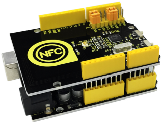
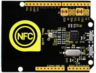
Keyestudio PN532 NFC/RFID Controller Shield based on PN532 chip is used for field communication close to 13.56MHz. This shield is equipped with an onboard antenna, so there is no external antenna coil. It is compatible with SPI, IIC, UART interface to communicate. When using it, directly stack it onto Arduino UNO R3 control board.
Specification
- Chip:NXP PN532
- Working Voltage:3.3V
- Power Voltage:3.3~5.5V
- Max Power Current:150mA
- Working Current (standby mode): 100 mA
- Working Current (write mode): 120 mA
- Working Current (read mode): 120 mA
- Pointer: PWR
- Longest effective communication distance is 5 cm
- Support SPI, IIC, UART interface switching.
- Can be used for 13.56M non-contact communication.
- Compatible with ISO14443 TYPE A and B standards.
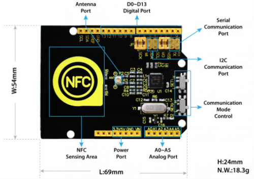
Related Explanation of Interface
Wiring Method
Stack the shield onto UNO R3 board.

Control Method of Interface Mode
| SET0 | SET1 | |
|---|---|---|
| UART | L | L |
| SPI | L | H |
| IIC | H | L |
Sample Code
Get the Libraries of PN532:[1] Get the Libraries of SPI: [2]
//This example reads a MIFARE memory block. It is tested with a new MIFARE 1K cards. Uses default keys.
//Contributed by Seeed Technology Inc (www.seeedstudio.com)

#include <PN532.h>
#include <SPI.h>

/*Chip select pin can be connected to D10 or D9 which is hareware optional*/
/*if you the version of NFC Shield from SeeedStudio is v2.0.*/
#define PN532_CS 10

PN532 nfc(PN532_CS);
#define  NFC_DEMO_DEBUG 1

void setup(void) {
#ifdef NFC_DEMO_DEBUG
  Serial.begin(9600);
  Serial.println("Hello!");
#endif
  nfc.begin();

  uint32_t versiondata = nfc.getFirmwareVersion();
  if (! versiondata) {
#ifdef NFC_DEMO_DEBUG
    Serial.print("Didn't find PN53x board");
#endif
    while (1); // halt
  }
#ifdef NFC_DEMO_DEBUG
  // Got ok data, print it out!
  Serial.print("Found chip PN5");
  Serial.println((versiondata>>24) & 0xFF, HEX);
  Serial.print("Firmware ver. ");
  Serial.print((versiondata>>16) & 0xFF, DEC);
  Serial.print('.');
  Serial.println((versiondata>>8) & 0xFF, DEC);
  Serial.print("Supports ");
  Serial.println(versiondata & 0xFF, HEX);
#endif
  // configure board to read RFID tags and cards
  nfc.SAMConfig();
}

void loop(void) {
  uint32_t id;
  // look for MiFare type cards
  id = nfc.readPassiveTargetID(PN532_MIFARE_ISO14443A);

  if (id != 0)
  {
#ifdef NFC_DEMO_DEBUG
    Serial.print("Read card #");
    Serial.println(id);
#endif
    uint8_t keys[]= { 0xFF,0xFF,0xFF,0xFF,0xFF,0xFF };
    if(nfc.authenticateBlock(1, id ,0x08,KEY_A,keys)) //authenticate block 0x08
    {
      //if authentication successful
      uint8_t block[16];
      //read memory block 0x08
      if(nfc.readMemoryBlock(1,0x08,block))
      {
#ifdef NFC_DEMO_DEBUG
        //if read operation is successful
        for(uint8_t i=0;i<16;i++)
        {
          //print memory block
          Serial.print(block[i],HEX);
          Serial.print(" ");
        }
        Serial.println();
#endif
      }
    }
  }
 delay(500);
}
Test Result
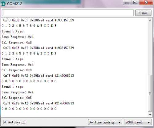
In the experiment, we use SPI communication, and SCK, MI, MO and NSS on the shield is connected with jumper cap. Dial SET0 to L, SET1 to H. After wiring and uploading the code to the board, open the serial monitor, respectively using S50 Fudan card and key chain to test it, you will get the information as the figure shown blow:
Resources
PDF
https://drive.google.com/open?id=1c96oFlawsJ3k-vWRw6Gkzhc3mhX13sZf
Get the Libraries of PN532
https://drive.google.com/open?id=1PHDePQzTCWEht9Js6X1aJkbW_N8gAjQm
Get the Libraries of SPI
https://drive.google.com/open?id=171BsjAyEi8_X69Nc37KXtd8SyyK41nz5
Get One Now
http://www.keyestudio.com/keyestudio-pn532-nfc-rfid-controller-shield.html


