Ks0183 keyestudio Multi-purpose Shield V1
Introduction
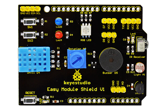
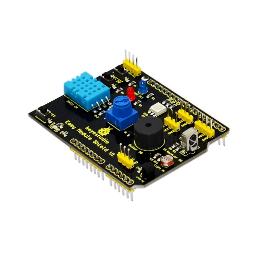
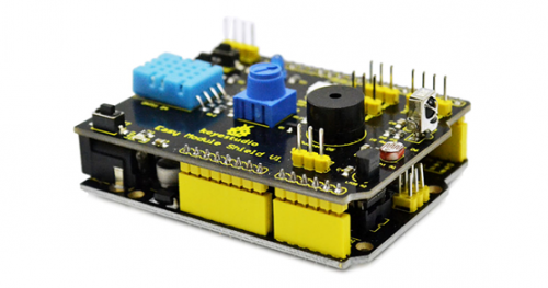
Multi-purpose Shield V1 is a learning board based on Arduino. No need for soldering and connection.Download the program to complete experiment.
It is multi-purpose and we offer code libraries of all modules that have been tested. You can use them directly.
There are extension ports on the shield to help you to complete other experiments.
Specification
- Compatible with main controllers such as UNO R3 and MEGA2560.
- Comes with 2 LED indicators to show the program status.
- Comes with 2 switches for external interrupt experiment.
- Comes with a reset button
- Comes with DHT11 sensor for measuring temperature and humidity.
- Comes with a potentiometer for analog input
- Comes with a passive buzzer for alarm.
- Comes with a full-color RGB LED
- Comes with a photocell to detect the brightness of light
- Comes with LM35D temperature sensor
- Comes with an infrared receiver
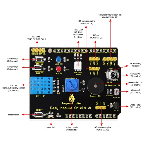
- 2digital pins(D7 and D8)
- 1 analog pin(A3)
- One IIC interface
- One TTL serial pin
Details
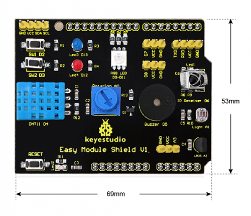
- Dimensions: 69mm*53mm*19mm
- Weight: 21g
Interface Instruction
Hookup Guide
Simply plug the shield into UNO R3 board.
Connection Diagram
Upload program to keyestudio UNO R3 BOARD, and plug this shield into UNO R3 BOARD.
Upload the Code
Note: Before compile the code, do remember to add the necessary libraries inside the libraries directory of Arduino IDE. You can download all the libraries from the link here: https://drive.google.com/open?id=1Fsr5NW8Ez8ziYh0jVmiviS9ldvR9NDei You can click here to download the code or directly copy the code below.
#include <IRremote.h>
#include <dht11.h>
dht11 DHT;
#define DHT11_PIN 4

//buzzer pin
int buzzer = 5;

//button pins
int KEY2 = 2;
int KEY3 = 3;

//pin definition of flowing light
int led5 = 13;
int led4 = 12;
int led3 = 11;
int led2 = 10;
int led1 = 9;

int RECV_PIN = 6; //define input pin on Arduino
IRrecv irrecv(RECV_PIN);
decode_results results;

char i=0,flag=2;
void setup ()
{
  Serial.begin(9600);

  irrecv.enableIRIn(); // Start the receiver

  attachInterrupt(0, falling0, FALLING);
  attachInterrupt(1, falling1, FALLING);

  pinMode(buzzer,OUTPUT);
  digitalWrite(buzzer,HIGH);

  pinMode(led1,OUTPUT);
  pinMode(led2,OUTPUT);
  pinMode(led3,OUTPUT);
  pinMode(led4,OUTPUT);
  pinMode(led5,OUTPUT);
  for(char i=9;i<14;i++)
   digitalWrite(i,LOW);
}

void loop()
{
  if(flag==0)
  {
  buzzer_();                //testing buzzer
  led_display();            //testing LED
  }
  if(flag==1)
  {
  Serial.println("status,  Hum(%),  Tem(C)      analog_val      light_val     lm35_val");
  DHT11();
  Serial.print("");
  analog();                //testing analog input
  Serial.print("");
  Light();
  Serial.print("");
  LM35();
  Serial.println("");
  delay(800);
  }
  if(flag!=0 & flag!=1)
  {
    if (irrecv.decode(&results))
     {
       Serial.println(results.value, HEX);
       irrecv.resume(); // Receive the next value
     }
  }
}

void DHT11()
{
int chk;
chk = DHT.read(DHT11_PIN);    // READ DATA
switch (chk)
  {
    case DHTLIB_OK:
                Serial.print("OK        ");
                Serial.print(DHT.humidity,1);
                Serial.print("");
                Serial.print(DHT.temperature,1);
                break;
    case DHTLIB_ERROR_CHECKSUM:
                Serial.print("Checksum error        ");
                break;
    case DHTLIB_ERROR_TIMEOUT:
                Serial.print("Time out error        ");
                break;
    default:
                Serial.print("Unknown error         ");
                break;
  }
}

void buzzer_(void)
{
 char i;
 for(i=0;i<80;i++)// output a frequency sound
 {
  digitalWrite(buzzer,LOW);// sound
  delay(1);//delay1ms
  digitalWrite(buzzer,HIGH);//not sound
  delay(1);//ms delay
 }
 for(i=0;i<100;i++)// output a frequency sound
 {
  digitalWrite(buzzer,LOW);// sound
  digitalWrite(buzzer,HIGH);//not sound
  delay(2);//2ms delay
 }
}

void led_display()
{
 digitalWrite(led1,HIGH);
 delay(500);
 digitalWrite(led1,LOW);
 digitalWrite(led2,HIGH);
 delay(500);
 digitalWrite(led2,LOW);
 digitalWrite(led3,HIGH);
 delay(500);
 digitalWrite(led3,LOW);
 digitalWrite(led4,HIGH);
 delay(500);
 digitalWrite(led4,LOW);
 digitalWrite(led5,HIGH);
 delay(500);
 digitalWrite(led5,LOW);
}

void analog()
{
int val;
val=analogRead(A0);
Serial.print(val);
}

void Light()
{
int val;
val=analogRead(A1);
Serial.print(val);
}

void LM35()
{
int val;
val=analogRead(A2);
Serial.print(val);
}

void falling0()
{
flag=0;
}
void falling1()
{
flag=1;
}
Test Result
Done uploading the code to the board, the power led 2 is normally on, open the serial monitor and set the baud rate to 9600.
Aimed at the IR receiver, press the buttons on IR remote control, you should see the decoding value of button is displayed on the monitor.
Do not press too long, or else appear the data error like FFFFFF.
Resources
Download Address of Libraries:
https://drive.google.com/open?id=1uq5r1EiJnRwRkjKRFLdxZYzkREg8r6BI
PDF Format:
https://drive.google.com/open?id=1JpWm7bxEAxZNm8ZbqsUbIhkTi0n7U4bY
Get One Now
Official Website
http://www.keyestudio.com/keyestudio-multi-purpose-shield-v1.html
