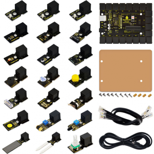
Ks0158 Keyestudio EASY plug starter kit for Arduino
EASY plug learning kit for Arduino starters
EASY plug starter kit for Arduino
Based on open-source hardware
19 various sensors in one box
For you to make interesting projects
Summary
What about you and your kids being makers? What about getting creative and making your ideas come true? Well, let's get started right away!
EASY plug learning kit is developed not only for professional electronic enthusiasts, but also for friends in other lines of work. Even if you have no electronics related knowledge, you can use it to realize your ideas as long as you want to.
The tutorial of this kit has fully considered the learning interest of beginners. Starting from the basics to more complex lessons, well-arranged content and a connection diagram for every lesson help you get started easily and quickly in learning Arduino.
Its unique EASY plug interface makes the wire connection easier than ever! You never have to worry about wrong connection or complicated soldering, avoiding component damage due to wrong wiring or wrong soldering. It's both safe and environmental-friendly.
Kit List
Lesson List
1.Hello world
2.Who's blinking
3.Visible breath
4.Flowing light
5.Make a sound
6.Who's singing
7.Temperature measuring
8.Make a sound-controlled lamp
9.Make a light-controlled lamp
10.Water level alarm
11.I'm thirsty
12.Visible analog value
13.Magnetic field detecting
14.Collision detecting
15.Button-controlled lamp
16.Touch alarm
17.Knock Sensing
18.Tilt Sensor
19.Fire alarm
20.Vibration alarm
21.Magnetic field detector
22.Temperature alarm
Lesson Details
Lesson 1: Hello world
Introduction
For the first lesson, we will begin with something simple. This lesson is called "Hello World!". This is a communication test of your Arduino and PC, also a primer project for you to have your first try of the Arduino world!
Hardware required
EASY plug controller Board *1
USB cable *1
Sample Code
Connect the board to your PC using the USB cable; copy below code into Arduino IDE, and click upload to upload it to your board.
int val;// define variable val
void setup()
{
  Serial.begin(9600);// set the baud rate at 9600 to match the software settings. When connected to a specific device, (e.g. Bluetooth), the baud rate needs to be the same with it.
}
void loop()
{
  val=Serial.read();// read the instruction or character from PC to Arduino, and assign them to Val.
  if(val=='R')//  determine if the instruction or character received is “R”
  {  // if it’s “R”
   Serial.println("Hello World!");// display “Hello World!”
  }
}
Result
Open serial port monitor of the Arduino IDE, input “R”, click “Send”, you can see it displays “Hello World!”.
Lesson 2: Who's blinking
Introduction
After entry lesson of “Hello World!”, let’s up the stake and learn how to control the blinking of an LED. This lesson is quite simple. All you need to do is to connect an LED to one of the digital pins. We will be using hardware form "Hello World!" and also some extra parts.
Hardware required
EASY plug controller Board *1
EASY plug cable *1
USB cable *1
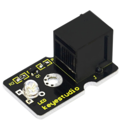
EASY plug Digital White LED Module *1
In the hardware list, you can see there is an EASY plug Digital White LED Module. Here is a brief introduction of it.
This LED module has a bright white color. It’s ideal for Arduino starters. You can easily connect it to the IO port of our EASY plug controller board. Its specifications are as below:
Type: Digital
PH2.54 socket
White LED module
Enables interaction with light-related works
Size: 33.7*20mm
Weight: 5g
Connection Diagram
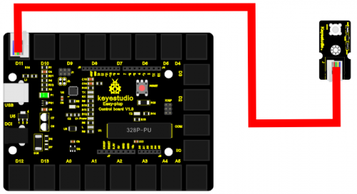
Now, let’s connect this module to the D11 port of the controller board using the EASY plug cable, just as simple as that!
Sample Code
Connect the board to your PC using the USB cable; copy below code into Arduino IDE, and click upload to upload it to your board.
int ledPin = 11; // define digital pin 11
void setup()
{
pinMode(ledPin, OUTPUT);// define LED pin as output
}
void loop()
{
analogWrite(ledPin,255); //set the LED on, regulate light brightness, ranging from 0-255, 255 is the brightest
delay(1000); // wait for a second
digitalWrite(ledPin, LOW); // set the LED off
delay(1000); // wait for a second
}
Result
The LED will be on for one second, and then off for one second with an interval of one second, just like a shining eye blinking.
Lesson 3: Visible breath
Introduction
After the first two lessons, I believe you’ve grown familiar with Arduino. In this lesson, we will use the LED to do something else, simulating breath. Sounds cool? Well, let’s get on with it. We will still be using the same hardware form lesson 2.
Hardware required
EASY plug controller Board *1
EASY plug cable *1
USB cable *1
EASY plug Digital White LED Module *1
Connection Diagram
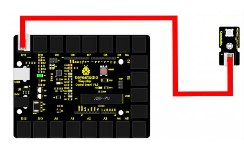
Now, connect the LED module to the D11 port of the controller board using the EASY plug cable.
Sample Code
Connect the board to your PC using the USB cable; copy below code into Arduino IDE, and click upload to upload it to your board.
int ledPin = 11; // define digital pin 11
void setup()
{
pinMode(ledPin, OUTPUT);// define LED pin as output
}
void loop()
{
for (int a=0; a<=255;a++)// set the LED to be brighter gradually
{
analogWrite(ledPin,a); // turn on LED, regulate light brightness, ranging from 0-255, 255 is the brightest
delay(10); // wait for 0.01S
}
for (int a=255; a>=0;a--) // set LED to be dimming gradually
{
analogWrite(ledPin,a); // turn on LED, regulate light brightness, ranging from 0-255, 255 is the brightest
delay(10); // wait for 0.01S
}
delay(1000);// wait for 1S
}
Result
LED becomes brighter gradually, wait for 0.01S, then dimming gradually, wait for 1S, and then cycles on, just like the LED is breathing.
Lesson 4: Flowing light
Introduction
LED can do many things. I believe you have seen billboards with lights changing to form various patterns. Now, you can make one! This lesson is called Flowing light. We will need 2 more EASY plug cables and 2 more LEDs than the previous lesson.
Hardware required
EASY plug controller Board *1
EASY plug cable *3
USB cable *1
EASY plug Digital White LED Module *3
Connection Diagram
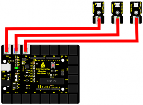
Now, connect the LED modules one by one to D9, D10 and D11 ports of the controller board using the EASY plug cables. LED becomes brighter gradually, wait for 0.01S, then dimming gradually, wait for 1S, and then cycles on, just like the LED is breathing.
Sample Code
Connect the board to your PC using the USB cable; copy below code into Arduino IDE, and click upload to upload it to your board.
int BASE = 9 ;  // the I/O pin for the first LED
int NUM = 3;   //  number of LEDs
void setup()
{
   for (int i = BASE; i < BASE + NUM; i ++)
   {
     pinMode(i, OUTPUT);   // set I/O pins as output
   }
}

void loop()
{
   for (int i = BASE; i < BASE + NUM; i ++)
   {
     digitalWrite(i, HIGH);    //set I/O pins as “high”, turn on LEDs one by one
     delay(200);        // wait 0.2S
   }
   for (int i = BASE; i < BASE + NUM; i ++)
   {
     digitalWrite(i, HIGH);    // set I/O pins as “low”, turn off LEDs one by one
     delay(200);        // wait 0.2S
   }
}
Result
3 LEDs turn on one by one, and then turn off one by one, just like flowing light.
Lesson 5: Make a sound
Introduction
After many light-related lessons, let’s learn how to make a sound. Sound experiment is usually done with a buzzer or a speaker, while buzzer is simpler and easier to use. In this lesson, we will learn how to make a sound with an active buzzer.
Hardware required
EASY plug controller Board *1
EASY plug cable *1
USB cable *1
EASY plug Active Buzzer Module *1
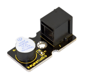
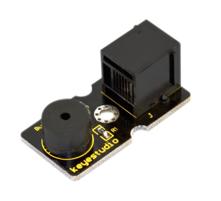
Here is a brief introduction of EASY plug Active Buzzer Module.
EASY plug Active Buzzer module is the simplest sound making module. It has an inner vibration source. Simply connect it with 5V power supply, it can buzz continuously. With Easy plug design, you can easily plug it into EASY plug controller board to have a try. Below are its specifications:
Working voltage: 3.3-5v
Interface type: digital
Size: 39*20mm
Weight: 6g
Connection Diagram
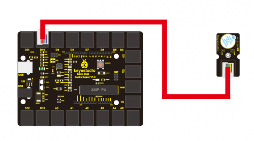
Now, connect the module to the D10 port of the controller board using the EASY plug cable.
Sample Code
Connect the board to your PC using the USB cable; copy below code into Arduino IDE, and click upload to upload it to your board.
int buzzPin =  10; // Connect Buzzer to D10
void setup()
{
 pinMode(buzzPin, OUTPUT);  // set I/O pin as “output”
}
void loop()
{
 digitalWrite(buzzPin, HIGH);// set digital I/O output as “high”, the buzzer will sound
 delay(500);// wait for 0.5S
 digitalWrite(buzzPin, LOW);// set digital I/O output as “low”, the buzzer will stop making sound
 delay(500); // wait for 0.5S
}
Result
The buzzer will ring for 0.5S and stop making sound for 0.5S.
Lesson 6: Who's singing
Introduction
In the previous lesson, we have learned how to make a sound. In this lesson, we will use another type of buzzer to code the melody of a song. It’s called a passive buzzer. Using the codes we gave you, this lesson is also quite simple.
Hardware required
EASY plug controller Board *1
EASY plug cable *1
USB cable *1
EASY plug Passive Buzzer module *1
Let’s first learn a little bit about this EASY plug passive Buzzer Module.
Different from active buzzer, passive buzzer is not set with a vibration source, so DC signal cannot make it buzz. A 2K~5K square wave is used to drive it. Different frequencies produce different sounds. So we can use Arduino to code the melody of a song. Below are its specifications:
Working voltage: 3.3-5v
Interface type: digital
Size: 39*20mm
Weight: 6g
Connection Diagram
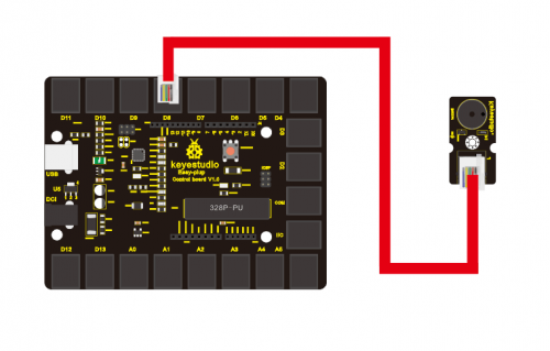
Now, connect the module to the D8 port of the controller board using the EASY plug cable.
Sample Code
#define D0 -1
#define D1 262
#define D2 293
#define D3 329
#define D4 349
#define D5 392
#define D6 440
#define D7 494

#define M1 523
#define M2 586
#define M3 658
#define M4 697
#define M5 783
#define M6 879
#define M7 987

#define H1 1045
#define H2 1171
#define H3 1316
#define H4 1393
#define H5 1563
#define H6 1755
#define H7 1971
// List all D tune frequency
#define WHOLE 1
#define HALF 0.5
#define QUARTER 0.25
#define EIGHTH 0.25
#define SIXTEENTH 0.625
// list all tempos
int tune[]=        // List each frequency according to numbered musical notation
{
  M3,M3,M4,M5,
  M5,M4,M3,M2,
  M1,M1,M2,M3,
  M3,M2,M2,
  M3,M3,M4,M5,
  M5,M4,M3,M2,
  M1,M1,M2,M3,
  M2,M1,M1,
  M2,M2,M3,M1,
  M2,M3,M4,M3,M1,
  M2,M3,M4,M3,M2,
  M1,M2,D5,D0,
  M3,M3,M4,M5,
  M5,M4,M3,M4,M2,
  M1,M1,M2,M3,
  M2,M1,M1
};
float durt[]=       // list all tempo according to numbered musical notation
{
  1,1,1,1,
  1,1,1,1,
  1,1,1,1,
  1+0.5,0.5,1+1,
  1,1,1,1,
  1,1,1,1,
  1,1,1,1,
  1+0.5,0.5,1+1,
  1,1,1,1,
  1,0.5,0.5,1,1,
  1,0.5,0.5,1,1,
  1,1,1,1,
  1,1,1,1,
  1,1,1,0.5,0.5,
  1,1,1,1,
  1+0.5,0.5,1+1,
};
int length;
int tonepin=8;   // set module signal pin to D8
void setup()
{
  pinMode(tonepin,OUTPUT);
  length=sizeof(tune)/sizeof(tune[0]);   // calculate length

}
void loop()
{
  for(int x=0;x<length;x++)
  {
    tone(tonepin,tune[x]);
    delay(500*durt[x]);   // this is use to adjust tempo delay, you can change the number to your liking.
    noTone(tonepin);
  }
  delay(2000);
}
Result The buzzer will play Ode to Joy, and then pause for 2S.
