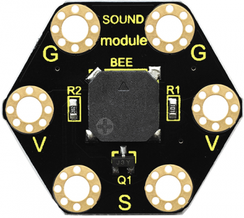
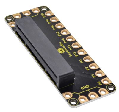
KS0456 Keyestudio Honeycomb Smart Wearable Coding Kit for Micro:bit
Kit Guide
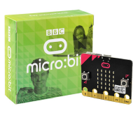
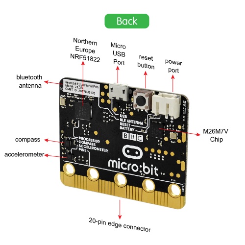
The BBC micro:bit is a tiny programmable computer designed to make learning and teaching easy and fun! This embedded board has a Bluetooth, USB interface, accelerometer, compass, light and temperature sensors, 5x5 LED matrix, buttons, and edge connectors for accessories.
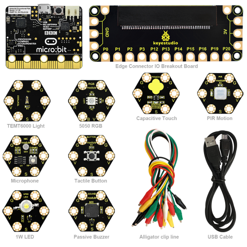
Keyestudio Honeycomb Smart wearable Kit for Micro:bit is designed for people who is at the door step of learning electric circuit and programming knowledge.
The kit has provided some basic electronic modules like RGB LED, button, buzzer, TEMT6000 light module and more. You can not only learn basic knowledge of these modules, but also use it to design circuit.
With the help of Micro:bit programming technique, your circuit becomes more animated. Micro:bit Starter kit can help you enter a wonderful of electronic world.
Kit List
micro:bit Driver Installation
Next, let’s install the driver for micro:bit main board.
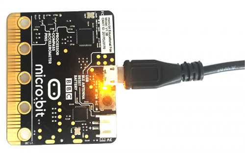
1) First of all, connect the micro:bit to your computer using a USB cable.
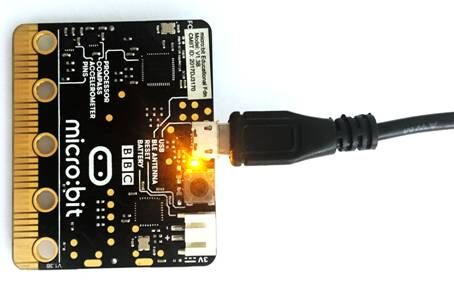
2)Then, double click the driver software to install it. Here you can click the icon below to download it.
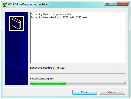
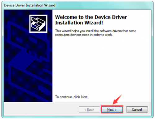
3) After that, click Next to continue the installation.
4) Wait the driver installing finished.
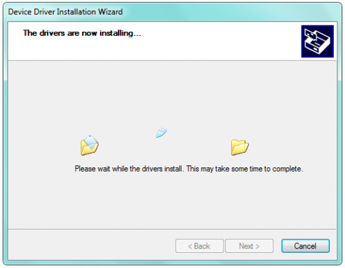
5) Wait the driver installing finished.
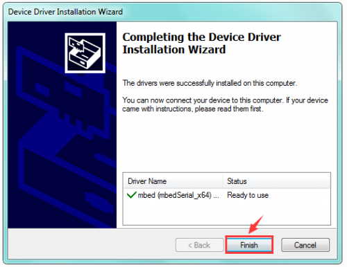
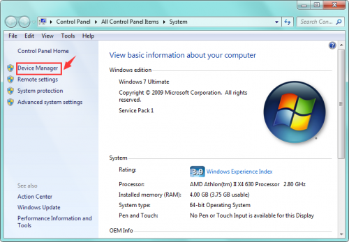
6) Driver installation completed, then you can right click the “Computer” —> “Properties”—> “Device Manager”.
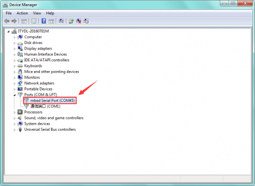
You can check the detailed Ports information shown as below.
micro:bit Example Use
Step 1: Connect It
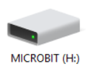
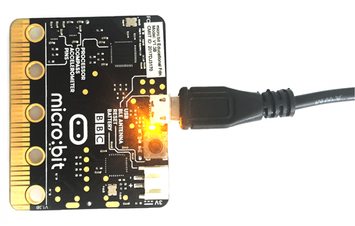
Connect the micro:bit to your computer via a micro USB cable. Your micro:bit will show up on your computer as a drive called 'MICROBIT'.
Step 2: Program It
Using micro bit MakeCode Block editor https://makecode.microbit.org/, write your first micro:bit code.
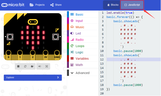
You can drag and drop some example blocks and try your program on the Simulator in the Javascript Blocks Editor, like in the image below.
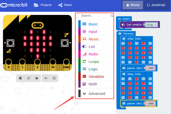
Click the JavaScript, you can see the corresponding program code. Shown as below figure.
Step 3: Download It
Click the Download button in the editor. This will download a 'hex' file, which is a compact format of your program that your micro:bit can read.
Here you can name the project as LED1, then click “Save”. Shown below.

Once the hex file has downloaded, copy it to your micro:bit just like copying a file to a USB drive. On Windows find the microbit-LED1 file, you can right click and choose "Send To→MICROBIT."


Step 4: Play It
The micro:bit will pause and the yellow 5*5 LED on the back of the micro:bit will display the images while your code is programmed.

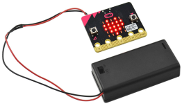
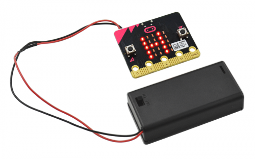
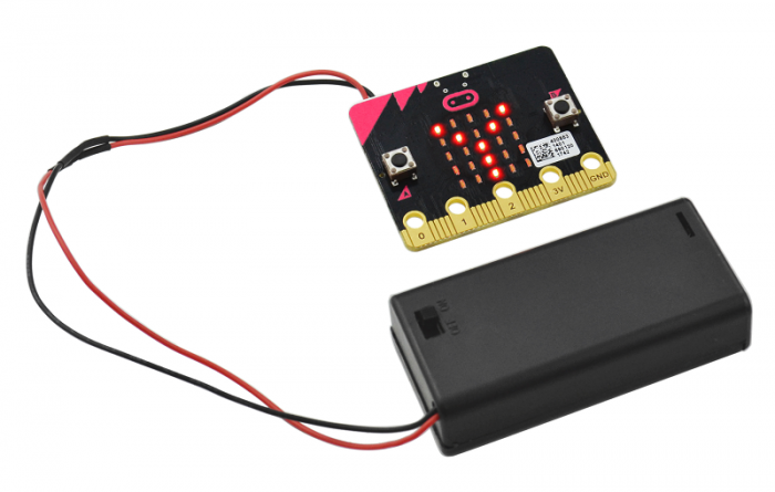
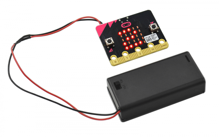
You can power it using USB cable or battery. The battery holder need to connect two 1.5V AA batteries. Shown below.
micro:bit Pins
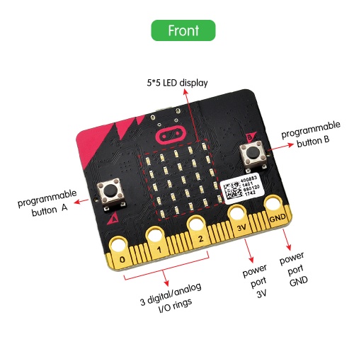
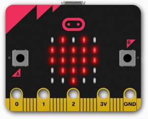
Before getting started with the following projects, first need to figure out each pin of micro:bit main board. Please refer to the reference diagram shown below.
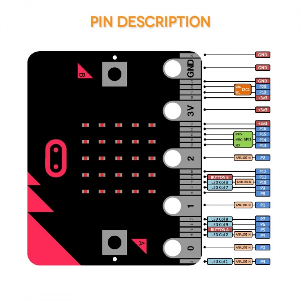
The BBC micro:bit has 25 external connections on the edge connector of the board, which we refer to as ‘pins’. The edge connector is the grey area on the right side of the figure above. There are five large pins, that are also connected to holes in the board labelled: 0, 1, 2, 3V, and GND. And along the same edge, there are 20 small pins that you can use when plugging the BBC micro:bit into an edge connector.
Note that it read from the BBC micro:bit official website. More reference you can click the link below:
BBC micro bit Pins: http://microbit.org/guide/hardware/pins/
BBC micro:bit website: http://microbit.org/
Micro bit MakeCode Block Editor: https://makecode.microbit.org/
Meet micro:bit starter programming: http://microbit.org/guide/
BBC micro:bit Features Guide: http://microbit.org/guide/features/
BBC micro:bit Safety Warnings: http://microbit.org/guide/features/
BBC micro:bit Quick Start Guide: http://microbit.org/guide/quick/
Getting Started with Micro:bit Projects
The BBC micro:bit is a tiny programmable computer designed to make learning and teaching easy and fun!
Combine the micro:bit main board, keyestudio Edge Connector IO Breakout Board for micro:bit, and other sensor modules to make your own micro:bit projects. Looking to discover more coding projects for micro:bit.
Project 1: Hello
Overview
This project is very simple. You can use only a micro:bit main board and a USB cable to display the “Hello!”.
This is an entry experiment for you to enter the programming world of micro:bit.
Components:
- Micro:bit main board*1
- USB cable*1
Pre-Test:
So let's test our micro:bit before programming it. There are two ways to test your micro:bit.
- 1.via USB cable: You can test your micro:bit just to see if it is working fine or not. To do so connect your micro:bit to your computer via USB cable and wait for a second your micro:bit will display "HELLO" by blinking LEDs. If it does, then it is working fine.
- 2.via Battery Connector: Insert batteries into battery box and connect your micro:bit via power pins and then see if it's displaying "HELLO". If it does, then it is working fine.
Coding
So now let's move to coding. Let us see how we can code and display "Hello" manually. Below are some steps to follow.
1. Open the https://makecode.micro:bit.org/#editor to write your code.
Microsoft MakeCode is actually a platform that allows us to code for a micro:bit, and also provides an interactive simulator where we can debug and run our code, and will be able to see what to expect out right there on the site.
Go to MakeCode and choose My Projects and click on New Projects.
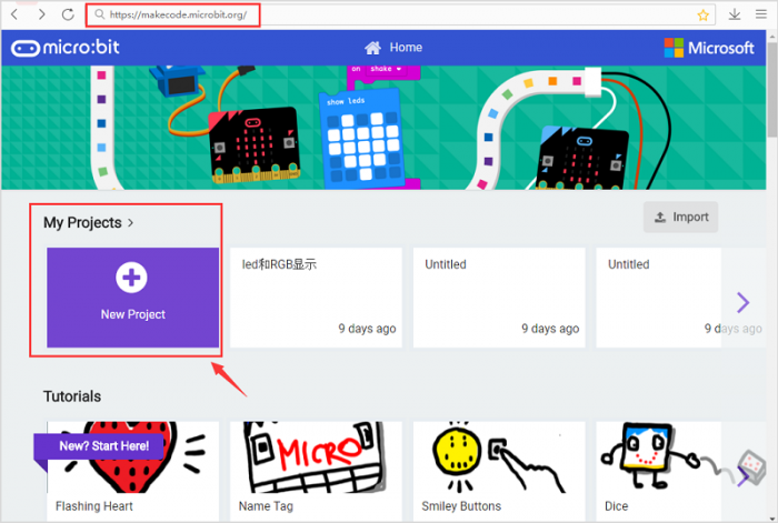
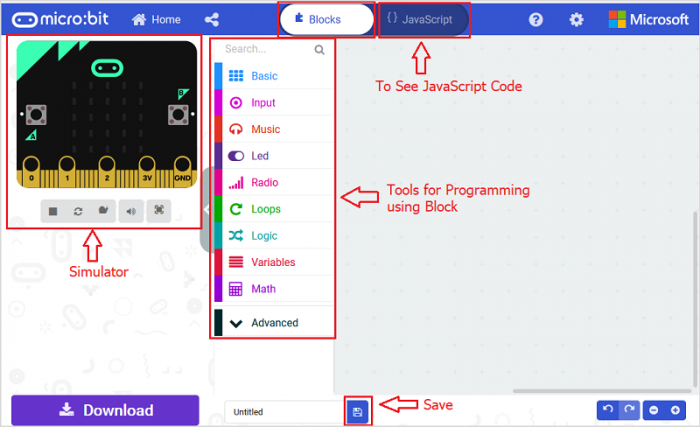
After this, you will see the following screen. As we can see that there is one micro:bit simulator, which will show the output instantly when we will finish writing our code.
2.Tools
We can see that there are different tools to program the micro:bit just next to simulator. It is quite easy to program by dragging and dropping the blocks, and if you want to see the codes behind, then you can click on JavaScript and it will display JavaScript code there in IDE.
3.Display "Hello,world!"
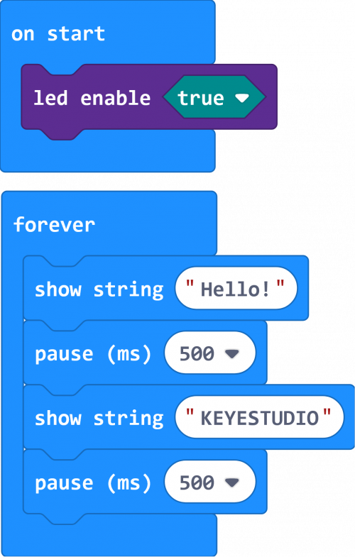
Let's get started and display "Hello, KEYESTUDIO!" on our micro:bit. To do so, you just need to go to Basic and scroll down to see an on start block.
Now drag and drop, and go to Led and click more to drag the block led enable(True) out;
And again go to Basic and search for the show string <hello> block. That's all; now you will see HELLO on your simulator.
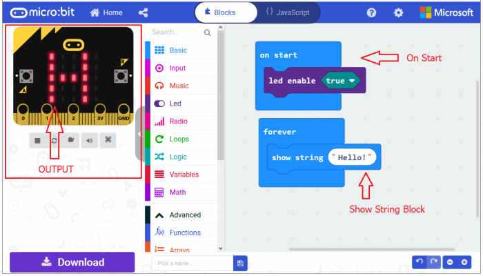
After completing this step micro:bit will restart itself and run the code. It will display "HELLO" there on the simulator. Quite easy? Yeah, quite easy. So let's move on and code for the rest.
Now drag and drop, and again go to Basic and search for the show string <hello> block; change the word to KEYESTUDIO and add a pause block in milliseconds.
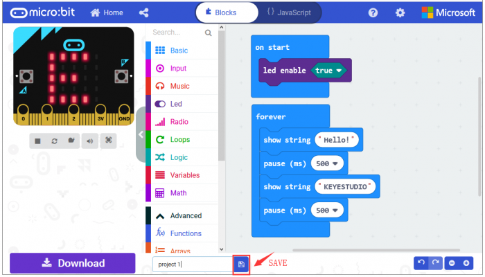
That's all for the coding part.
Name and download your program that you have written.

Run Code on Micro:bit
Now let us see how to run our code on the actual Micro:bit.
- Plug in the Micro:bit to a computer via USB.
- After plugging in, you should see Micro:bit drive on your computer.
Now go to your download folder and right-click to send the downloaded microbit Hex file to your micro:bit main board.
Now wait for a second for Micro:bit to restart, and it will start displaying output automatically.
Project 2: Buttons
Overview
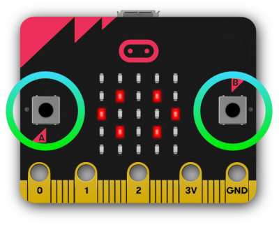
The micro:bit main board comes with 3 buttons. One for reset; button A and B are used as control button. The micro:bit has 25 individually-programmable LEDs, allowing you to display text, numbers, and images.
In this project, we are going to use the two built-in buttons to make the LED matrix showing the patterns.
There are two test codes for you. One is without loop function; the other is with loop function.
Hardware Components:
- Micro:bit main board*1
- USB cable*1
Coding
So now let's move to coding. Let us see how we can code and display different icons via button control. Below are some steps to follow.
Open the https://makecode.micro:bit.org/#editor to write your code.
Microsoft MakeCode is actually a platform that allows us to code for a micro:bit, and also provides an interactive simulator where we can debug and run our code, and will be able to see what to expect out right there on the site.
Go to MakeCode and choose My Projects and click on New Projects.
If you want to see the codes behind, then you can click on JavaScript and it will display JavaScript code there in IDE.

LED Display
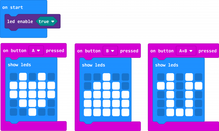
Let's get started and display different icons on our micro:bit. To do so, you just need to go to Basic and scroll down to see an on start block.
Now drag and drop, and go to Led and click more to drag the block led enable(false) out; choose true.
On the micro:bit main board, we can see the button A and B. Now we set the buttons to make the led matrix show different icons.
Now go to input, drag and drop the block on button()pressed; and duplicate it twice. Separately change the button to button A, B, A+B.
And again go to Basic and search for the show leds block; duplicate the block twice and drag these blocks into the button block you just made.
You can show different icons as you like by drawing the leds.
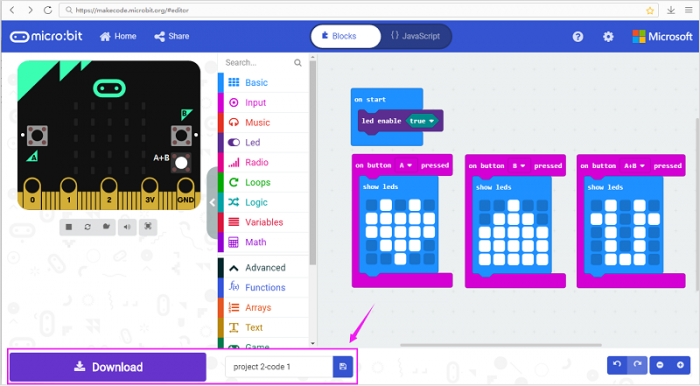
After completing this step micro:bit will restart itself and run the code. It will display icons on the simulator. Quite easy? Yeah, quite easy. So let's move on and name and download the program you’ve written.

Run Code on Micro:bit
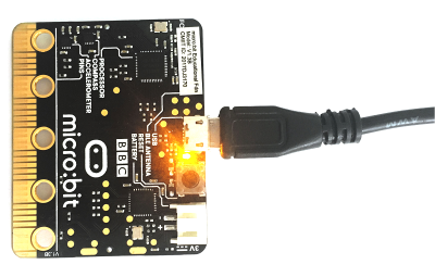
Downloaded well the code, connect the micro:bit to your computer with a micro USB cable. You can right-click the microbit HEX file to send to your micro:bit main board. See what will show on micro:bit.
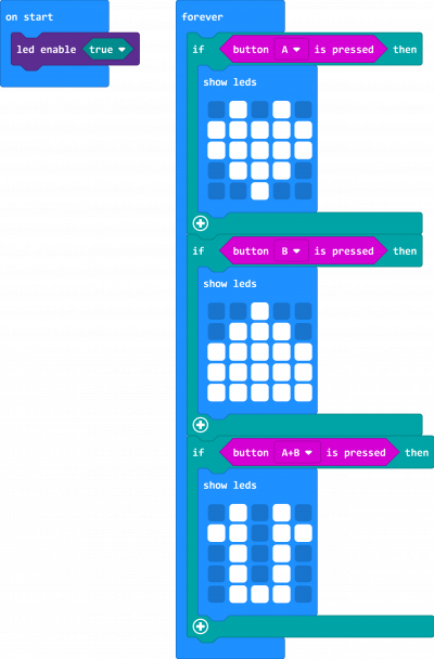
Furthermore, you can change to use the forever block and logic conditionals to make the same function.
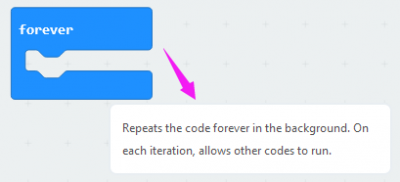
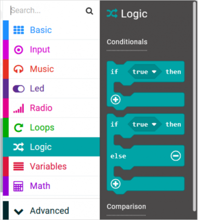
Go to the Basic and scroll down to see a forever block. Now drag and drop, and go to Logic and search for if (true) then ... block. Drag this block into forever block.
Go to input, drag and drop the block button () is pressed to replace the (true). And again go to Basic and search for the show leds block; change the led display as you want. We draw a big heart shape.
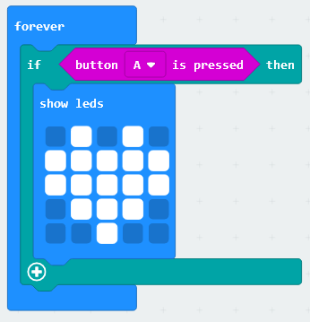
So let's move on and can duplicate this whole block twice. Just change the button and leds show.
Go to finish the code by yourself. After that, download and send the microbit hex file to your micro:bit main board. See what result it will make.
Result
Done sending the code 1 or code 2 to micro:bit.
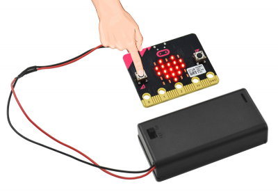
Press down the button A, LED matrix on the micro:bit main board will show a heart shape icon.
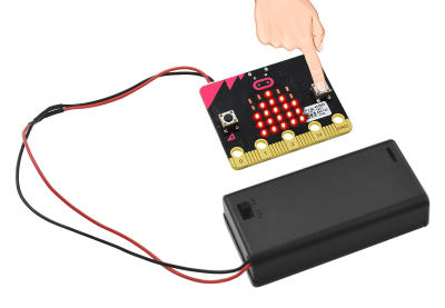
Press the button B, LED matrix will show a diamond shape icon.
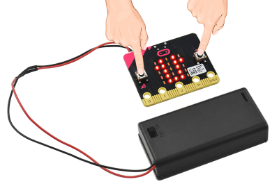
Press the button A and B at the same time, LED matrix shows another different icon.
Project 3: Accelerometer
Overview
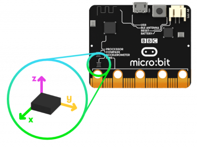
An accelerometer measures the acceleration of your micro:bit; this component senses when the micro:bit is moved.
The compass detects the earth's magnetic field, allowing you to detect which direction the micro:bit is facing.
In this project, you will learn how to use both accelerometer and compass to make LED matrix show the images. Besides, learn to test the 3-axis acceleration, showing on the LED matrix and serial monitor.
Components:
- Micro:bit main board*1
- USB cable*1
Coding
So now let's move to coding. Let us see how we can code and display different icons via controlling the micro:bit direction. Below are some steps to follow.
Open the https://makecode.micro:bit.org/#editor to write your code.
Microsoft MakeCode is actually a platform that allows us to code for a micro:bit, and also provides an interactive simulator where we can debug and run our code, and will be able to see what to expect out right there on the site.
Go to MakeCode and choose My Projects and click on New Projects.
If you want to see the codes behind, then you can click on JavaScript and it will display JavaScript code there in IDE.
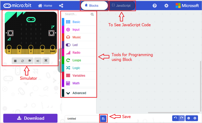
LED Display
Let's get started and display different icons on our micro:bit when move micro:bit in different direction. To do so, you just need to go to Basic and scroll down to see an on start block.
Now drag and drop, and go to Led and click more to drag the block led enable(false) out; choose true.
Now go to input, drag and drop the block on (shake); and duplicate it for six times. Choose the posture you want.
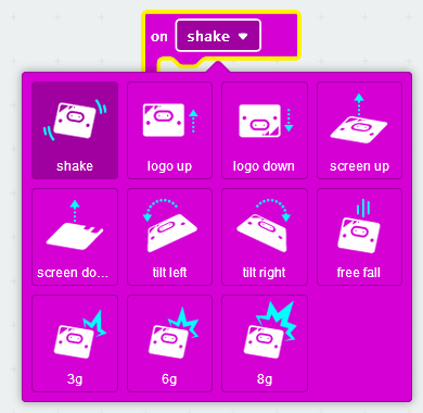
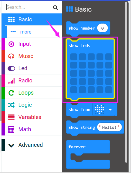
And again go to Basic and drag the show leds block into the block you just made. You can duplicate the leds display block and choose to draw different led icons as you like.
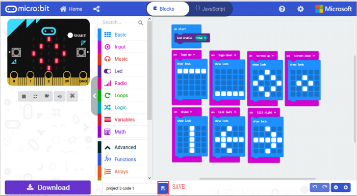
So let's move on and name and download the program you’ve written.
![]()
Run Code on Micro:bit
Downloaded well the code, connect the micro:bit to your computer with a micro USB cable. You can right-click the microbit HEX file to send to your micro:bit main board. See what will show on micro:bit when move the micro:bit.
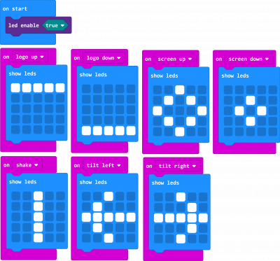
Code 1:
Result
Done sending the code 1 to micro:bit, when we move the micro:bit logo up, LED matrix will show the first icon set in the code;
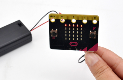
Move the micro:bit pin logo down, LED matrix will show the second icon set in the code;
Place the micro:bit horizontally, make the matrix screen up, LED matrix will show the third icon set in the code;
Place the micro:bit horizontally, make the matrix screen down, LED matrix will show the fourth icon set in the code;
Shake the micro:bit board, LED matrix will show the fifth icon set in the code;
When the micro:bit main board is tilted left, LED matrix will show a left arrow icon; if tilted right, LED matrix will show a right arrow icon.

Showing X-Y-Z axis Data
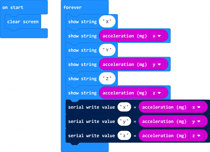
Go further, let's get started and display acceleration X-Y-Z axis data on our micro:bit when move micro:bit in different direction.
To run code when the program starts, you just need to go to Basic and scroll down to see an on start block.
Now drag and drop, and again go to Basic and click more to drag the block clear screen out; means turn off all LEDs.
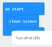
Now go to the Basic and scroll down to see a forever and show string block. Now drag and drop, and duplicate it. Change the word to a capital letter.
Go to input, drag and drop the block acceleration(mg){x} into show string block.
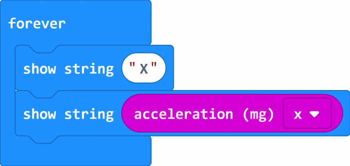
Duplicate this piece of block for several times, and separately change the string <hello> block to X, Y, Z.
Next, we go to Serial, drag and drop the block serial write value(x)=(0)
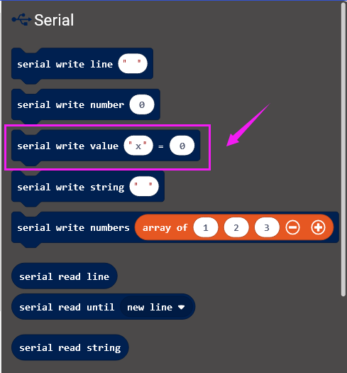
In this way it can write the acceleration value to the serial port and show it on monitor. Go to input, drag and drop the block acceleration(mg){x} to replace the (0) field.

After that, duplicate this piece of code block twice and change the value to Y, Z.
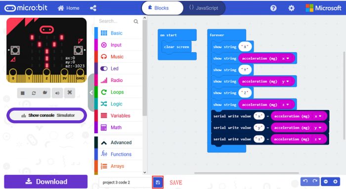
So let's move on and name and download the program you’ve written.
![]()
Run Code on Micro:bit
Downloaded well the code, connect the micro:bit to your computer with a micro USB cable. You can right-click the microbit HEX file to send to your micro:bit main board. See what will show on micro:bit when move the micro:bit.

Result
Done sending the code 2 to micro:bit, we can work out the 3-axis X, Y, Z acceleration data, with a unit of mg.
On one hand, see the data scroll on the micro:bit LED matrix; on the other hand, check the data on the serial monitor of Arduino IDE.
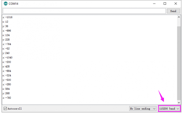
Note: the baud rate of micro:bit is defaulted by 115200.
Project 4: Temperature
Overview
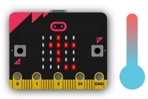
The temperature sensor allows the micro:bit to detect the current temperature of the device, in degrees and Celsius.
In this project, you will learn how to use the temperature sensor to detect the ambient temperature, showing the data on the LED matrix.
Components:
- Micro:bit main board*1
- USB cable*1
Coding
So now let's move to coding. Let us see how we can code and display ambient temperature value. Below are some steps to follow.
Open the https://makecode.micro:bit.org/#editor to write your code.
Microsoft MakeCode is actually a platform that allows us to code for a micro:bit, and also provides an interactive simulator where we can debug and run our code, and will be able to see what to expect out right there on the site.
Go to MakeCode and choose My Projects and click on New Projects.
If you want to see the codes behind, then you can click on JavaScript and it will display JavaScript code there in IDE.

Temperature Display
Let's get started and display ambient temperature value on our micro:bit. To do so, you just need to go to Basic and scroll down to see an on start block.
Now drag and drop, and again go to Basic and click more to drag the block clear screen out; means turn off all LEDs.

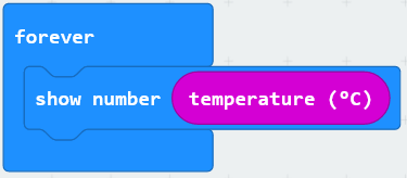
Now go to the Basic and scroll down to see a forever and show number(0) block. Drag the forever block beneath the on start block. And drag the show number(0) block into the forever block.
Go to input, drag and drop the block temperature (℃) into show number(0) block, replacing the “0” field.
Next, we go to Serial, drag and drop the block serial write value(x)=(0)
In this way it can write the acceleration value to the serial port and show it on monitor. Change the “x” to temperature and duplicate the block temperature (℃) to replace the “0” field.

And again go to Basic and search for the pause(ms) block; drag this block into the serial write value block you just made. Give a delay time in milliseconds to output the data.
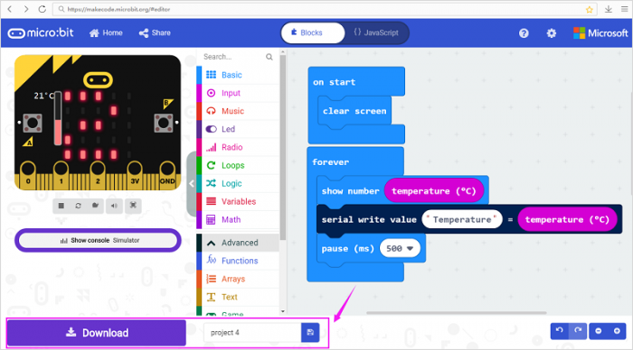
After completing this step micro:bit will restart itself and run the code. It will display icons on the simulator. Quite easy? Yeah, quite easy.
So let's move on and name and download the program you’ve written.
File:456图片-28.png
Run Code on Micro:bit
Connect the micro:bit to your computer with a micro USB cable. You can right-click the microbit HEX file to send to your micro:bit main board.
Result
Done sending the code to micro:bit, it can work out the current ambient temperature, with unit of ℃.
On one hand, see the data scroll on the micro:bit LED matrix; on the other hand, check the data on the serial monitor of Arduino IDE. Shown below.
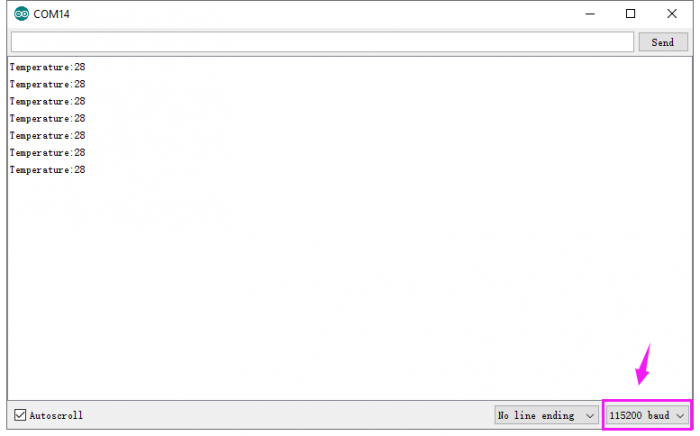
Note: the baud rate of micro:bit is defaulted by 115200.
Project 5: Bluetooth
Overview
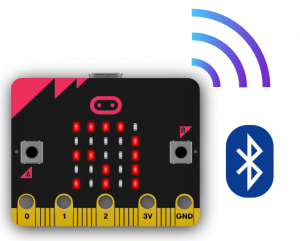
The BLE (Bluetooth Low Energy) allows the micro:bit to control phones and tablets over Bluetooth.
In this project, we connect micro:bit with ipad to realize the wireless transmission code function. Note the use methods of Android phone is similar to the ipad’s.
Components:
- Micro:bit main board*1
- USB cable*1
Connect the micro:bit to your computer with a micro USB cable.
Test Steps
① Open the App store on your ipad/iPhone.
Search the micro:bit to download and install.

Pair ipad and micro:bit main board for connection.
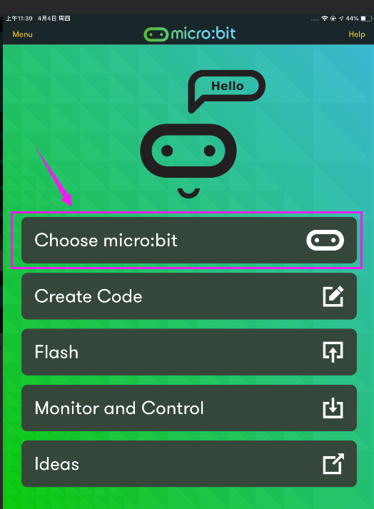
② Open the micro:bit APP, click Choose micro:bit to pair the Bluetooth.
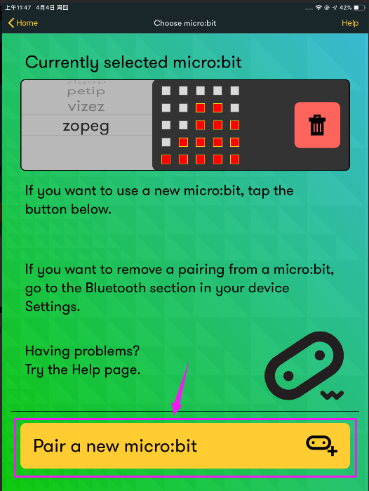
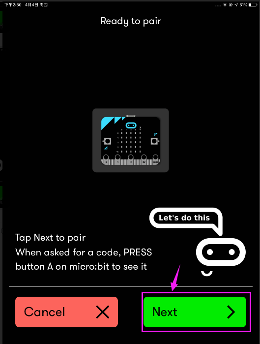
③ Click Pair a micro:bit, and click Next.
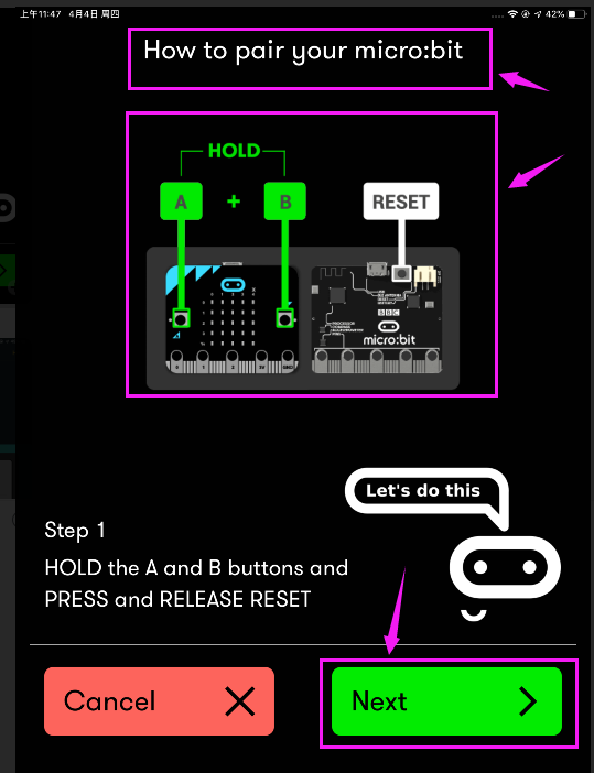
④Power on the micro:bit main board, HOLD the A and B buttons, then press and release RESET button. The micro:bit main board will enter the Bluetooth pairing mode. You should see an image showing on the LED matrix.
Then click “Next”.
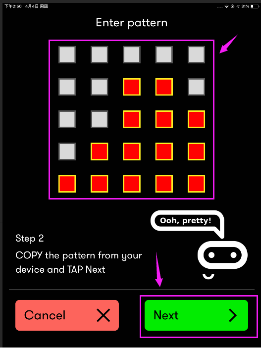
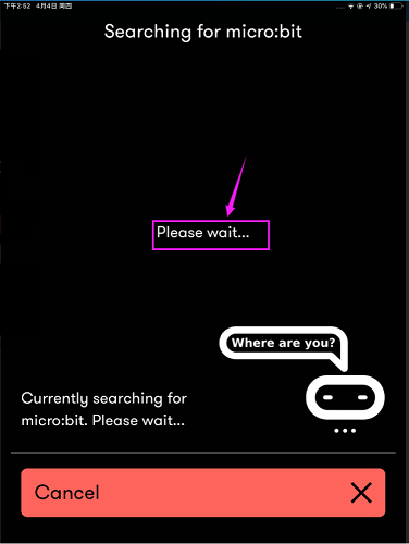
⑤ Copy the pattern from your micro:bit device and tap Next.
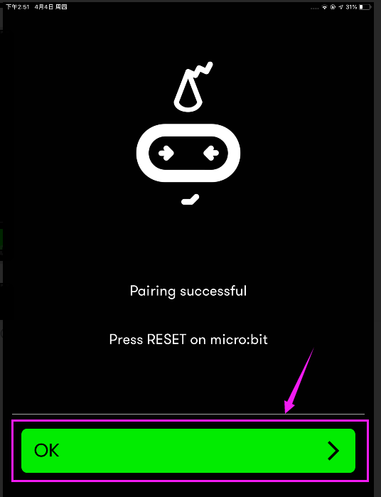
⑥ OK, pairing successful!
Create Code
Pairing successful, we begin to write the code with APP.
Open the APP, tap Create Code to write your code.
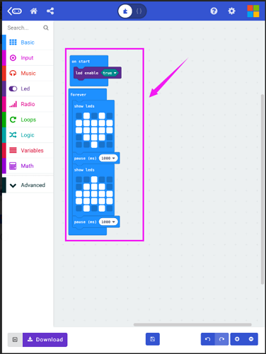
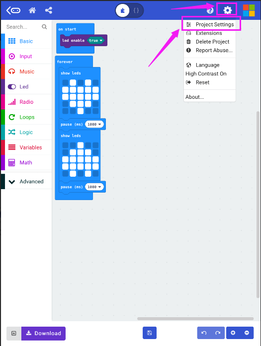
Click settings gear , choose Project Settings.
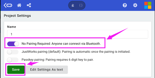
Open the first option No Pairing Required, and save the settings.
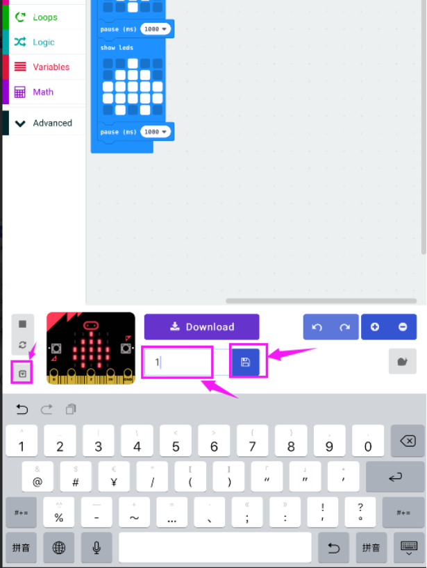
Tap icons to set the project name and save it.
Done saving the code, direct to upload the code you just made.
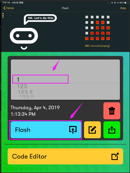
Special note: uploading the code, make sure the LED matrix display the icon, so that the code upload success.
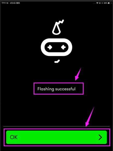
Done uploading the code, appear the interface as shown below. Flashing successful.
Project 6: LED Flash
Overview
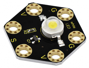
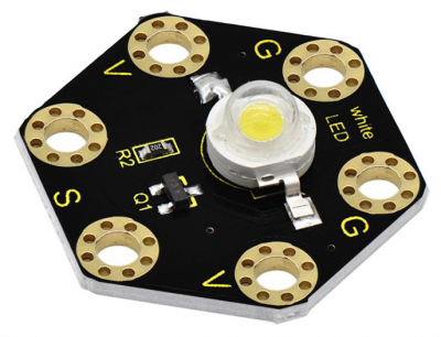
keyestudio 1W LED Module For BBC micro:bit (Black and Eco-friendly)
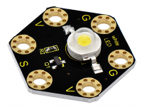
This LED module is fully compatible with micro:bit control board. It will emit the white light. The maximum operating current is 400mA, and the maximum power is 1W. When using, connect the LED module to micro:bit control board using Crocodile clip line.
There are total 6 rings on the module. Two G rings, two V rings and two S rings are separately connected.
When using, G ring for ground; V for 3V; S for signal pin (0 1 2). When signal end is HIGH, LED lights.
Technical Parameters
- Working voltage: DC 3.0-3.3V
- Working current: 400mA
- Power: 1W
- Light Color: white
- Dimensions: 31mm*27mm*8mm
- Weight: 2.4g
- Environmental attributes: ROHS
Hardware Required:
- Micro:bit main board *1
- keyestudio 1W LED Module for micro:bit *1
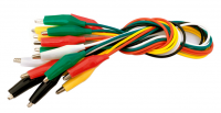
- Alligator clip cable *3
- USB cable *1
Connection Diagram
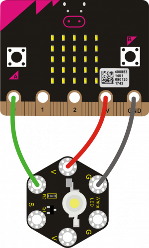
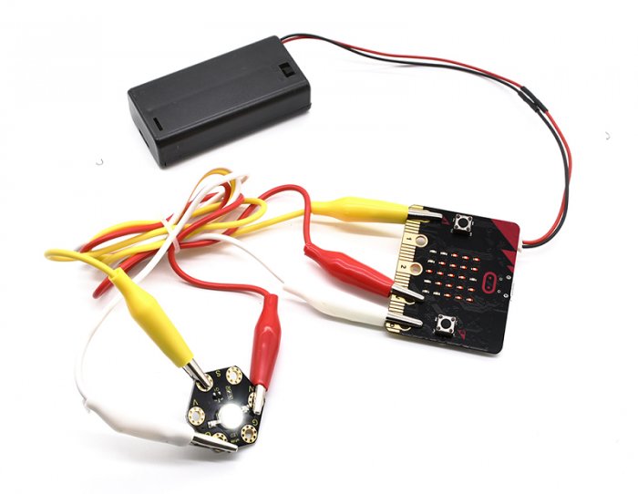
Connect the keyestudio 1W LED Module to micro:bit main board with 3 Alligator clip cables. Ring S to P0, V to 3V, G to GND. Connect the micro:bit to your computer with a micro USB cable.
Coding
So now let's move to coding. Let us see how we can code the LED flash. Below are some steps to follow.
Open the https://makecode.micro:bit.org/#editor to write your code.
Microsoft MakeCode is actually a platform that allows us to code for a micro:bit, and also provides an interactive simulator where we can debug and run our code, and will be able to see what to expect out right there on the site.
Go to MakeCode and choose My Projects and click on New Projects.
If you want to see the codes behind, then you can click on JavaScript and it will display JavaScript code there in IDE.

LED Flash
Let's get started and code the LED flash. To do so, you just need to go to Basic and scroll down to see an on start block.
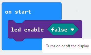
Now drag and drop, and go to Led and click more to drag out the block led enable(false) into on start block.
And again go to Basic and drag the forever block beneath the on start block you just made.
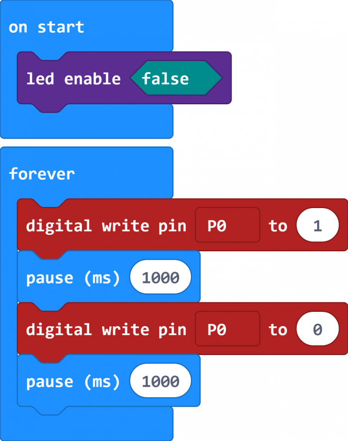
Go to the Pins, drag and drop the digital write pin(P0) to (0) block into forever block.
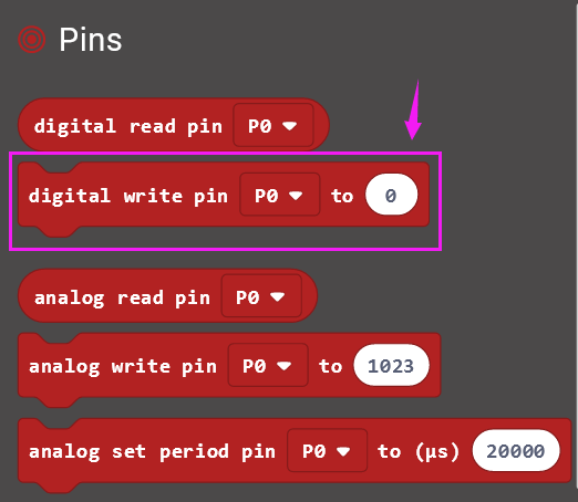
Look back at the connection diagram, we connect the signal pin to P0. So we select the P0 in the code; and change the 0 to 1, which means input a HIGH level to the pin so as to lit the LED.

Then we can duplicate the block and change the value to 0, means input a LOW level to the pin to turn off the LED.
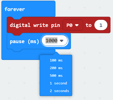
If we want to make the LED keep ON for a few seconds, able to add a pause (ms) block. This delay period is in milliseconds, so if you want the LED display as fast, change the value, try 500ms.
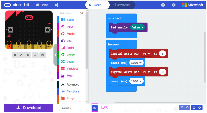
After completing the code, let's move on to name and download the program we’ve written.
![]()
Source Code:
Run Code on Micro:bit
Connect the micro:bit to your computer with a micro USB cable. You can right-click the microbit HEX file to send to your micro:bit main board.
![]()
Powered the microbit with batteries, the LED on the module should flash for one second, then off for one second, circularly and alternately.
Project 7: RGB Flash
Overview
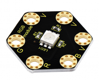
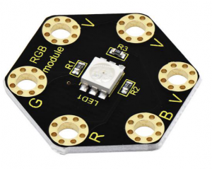
keyestudio 5050 RGB Module For BBC micro:bit
This module mainly contains a 5050 RGB LED, fully compatible with micro:bit control board.
When using, connect the RGB module to micro:bit control board using Crocodile clip line.
There are total 6 rings on the module. Note that three V rings are connected. V ring for 3V; R G B ring is separately connected to signal pin (0 1 2) of micro:bit main board.
When three signal pins are LOW, module will gradually show red, green and blue light.
Technical Parameters
- Working voltage: DC 3.0-3.3V
- Control mode: active LOW(common anode)
- Dimensions: 31mm*27mm*3mm
- Weight: 1.8g
- Environmental attributes: ROHS
Hardware Required:
- Micro:bit main board *1
- keyestudio 5050 RGB Module for micro:bit *1
- Alligator clip cable *4
- USB cable *1
Connection Diagram
Connect the keyestudio 5050 RGB Module to micro:bit main board with 4 Alligator clip cables. Ring B to P0, R to P1, G to GND, V to 3V.
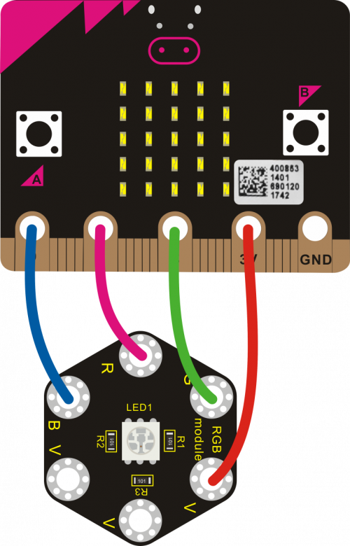
Coding
So now let's move to coding. Let us see how we can code the RGB LED flash. Below are some steps to follow.
Open the https://makecode.micro:bit.org/#editor to write your code.
Microsoft MakeCode is actually a platform that allows us to code for a micro:bit, and also provides an interactive simulator where we can debug and run our code, and will be able to see what to expect out right there on the site.
Go to MakeCode and choose My Projects and click on New Projects.
If you want to see the codes behind, then you can click on JavaScript and it will display JavaScript code there in IDE.

RGB LED Flash
Let's get started and code RGB LED shine three colors. To do so, you just need to go to Basic and scroll down to see an on start block.
Now drag and drop, and go to Led and click more to drag out the block led enable(false) into on start block.

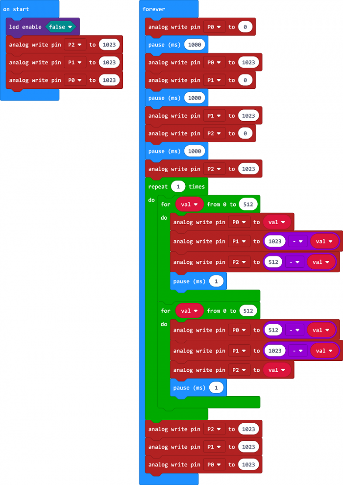
Go to the Pins, drag and drop the analog write pin(P0) to (1023) block into forever block. Duplicate this block twice, and change the pin to P1, P2.
Look at the connection diagram, we separately connect the Red,Green, Blue pin to P1, P2, P0. Connect the V pin to 3.3V.
So we first set all the pin value to 1023, which means input a HIGH level 3.3V (no voltage difference) to turn off all the LEDs;
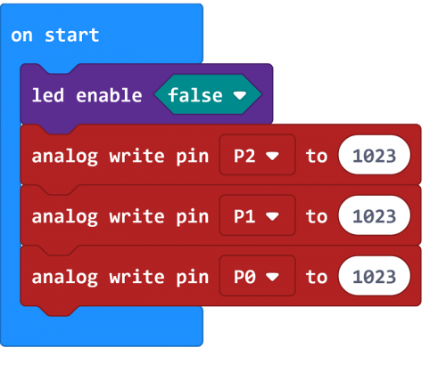
And again go to Basic and drag the forever block beneath the on start block you just made.
We duplicate and drag the analog write pin(P0) to (1023) block into the forever block. Change the P0 value to 0, which means input a LOW level (0V)(with voltage difference) so as to lit the Blue LED.
Add a pause block in millisecond; and then duplicate the analog write pin(P0) to (1023) block several times.
We first turn on the Blue LED (P0) for 1 second then off, followed by turn Red LED (P1) on for 1 second then off; and turn Green LED (P2) on for 1 second then off.
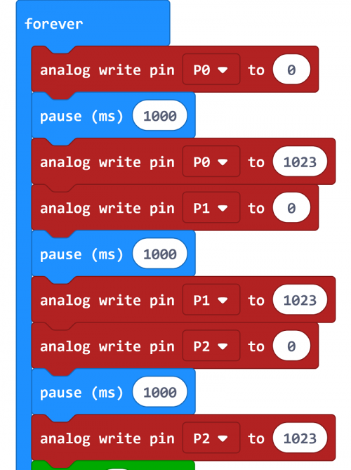
Now let's move on code the program we’ve written. Go to make the RGB led change in different brightness.
Go to Loops, drag and drop the repeat()times do() block into the block just made. Repeat 1 times.
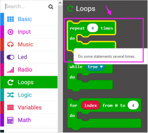
Then we drag the block for (index) from 0 to (4) do into the repeat()times do() block; and set to the variable val from 0 to 512.
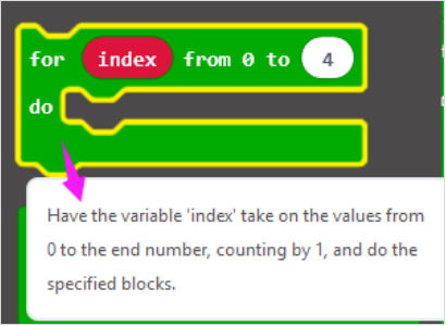
After that, duplicate the analog write pin block three times; then call the Variables and Math block.
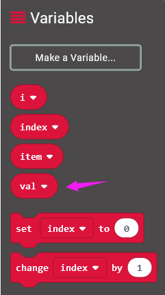
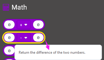
Using the variables adjust the RGB color-ratio to make the color change.
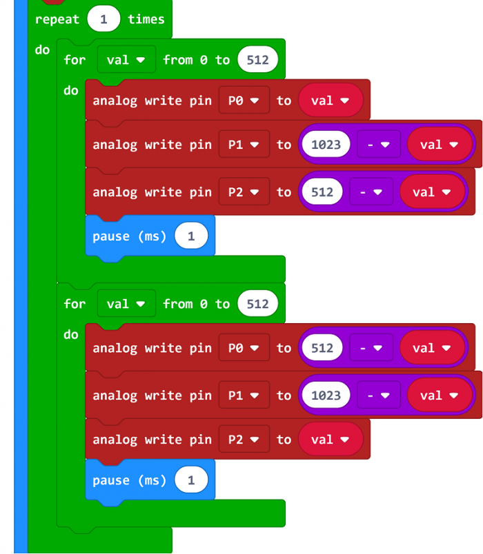
Finally we duplicate and set the analog write pin 2, 1, 0 value to 1023, which means input a HIGH level (no voltage difference) to turn off all the LEDs.
You can click on JavaScript and it will display JavaScript code there in IDE.
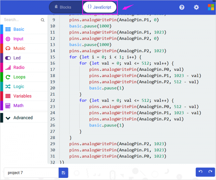
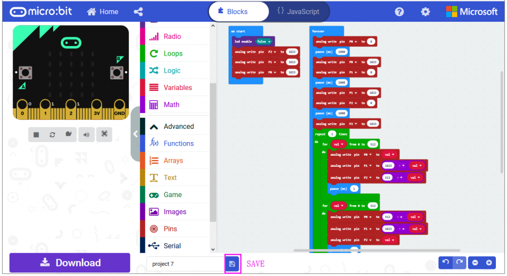
After completing the code, let's move on to name and download the program we’ve written.

Run Code on Micro:bit
Connect the micro:bit to your computer with a micro USB cable. You can right-click the microbit HEX file to send to your micro:bit main board.
Powered on, the RGB LED on the module will alternately flash red, blue and green light and make a slight brightness change.
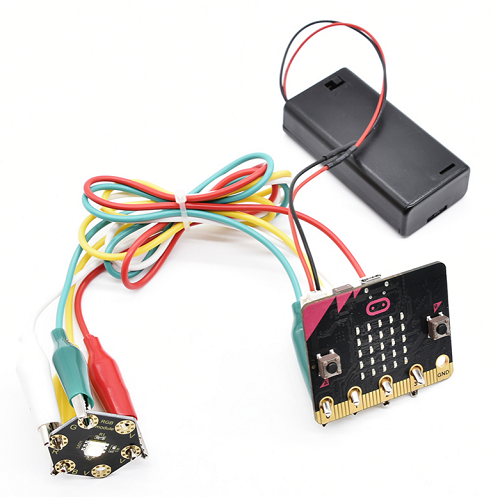
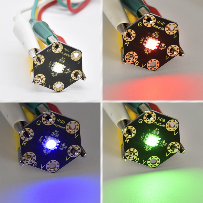
Project 8: Tactile Button
Overview
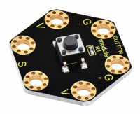
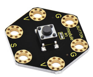
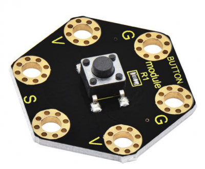
keyestudio Tactile Button Module For BBC micro:bit
This keyestudio tactile button module is fully compatible with micro:bit control board. It mainly uses a button element, which is a digital signal output device.
When using, connect the module to micro:bit control board using Crocodile clip line.
There are total 6 rings on the module. Note that two G rings, two V rings and two S rings are connected. G for ground; V for 3V; S for signal pin(0 1 2).
When press the button, the signal end of micro:bit main board will input HIGH level signal.
Technical Parameters
- Working voltage: DC 3.0-3.3V
- Output Signal: Digital
- Dimensions: 31mm*27mm*6.5mm
- Weight: 1.8g
- Environmental attributes: ROHS
Hardware Required:
- Micro:bit main board *1
- Keyestudio Tactile Button Module for micro:bit *1
- Alligator clip cable *3
- USB cable *1
Connection Diagram
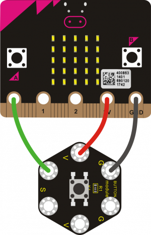
Connect the keyestudio Tactile Button Module to micro:bit main board with 4 Alligator clip cables. Ring S to P0, V to 3V, G to GND.
Connect the micro:bit to your computer with a micro USB cable.
Coding
So now let's move to coding. Let us see how we can code the microbit LED matrix show icons with button module. Below are some steps to follow.
Open the https://makecode.micro:bit.org/#editor to write your code.
Microsoft MakeCode is actually a platform that allows us to code for a micro:bit, and also provides an interactive simulator where we can debug and run our code, and will be able to see what to expect out right there on the site.

Go to MakeCode and choose My Projects and click on New Projects.
If you want to see the codes behind, then you can click on JavaScript and it will display JavaScript code there in IDE.
Button Controlling LED Display
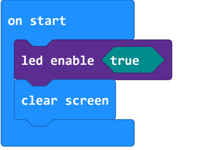
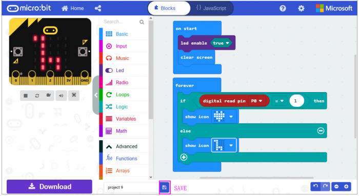
Let's get started and show icons on micro:bit using button control. To do so, you just need to go to Basic and scroll down to see an on start and clear screen block.
Now drag and drop, and go to Led and click more to drag out the block led enable(true) into on start block.
And again go to Basic and drag the forever block beneath the on start block you just made.
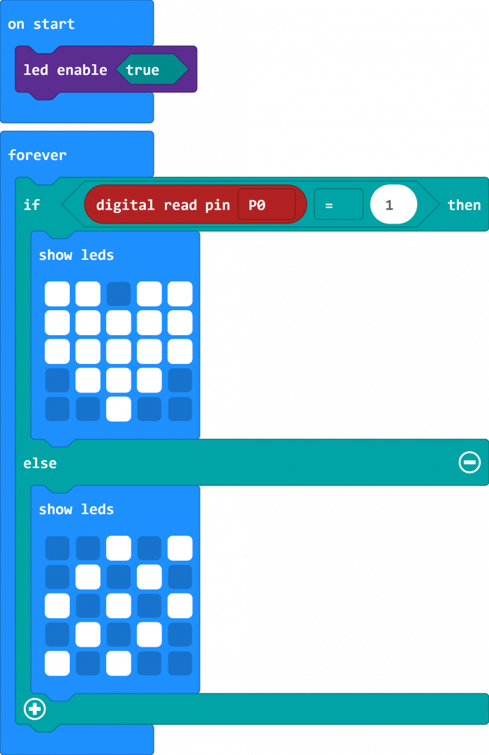
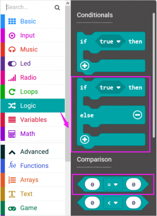
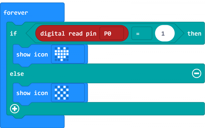
Now drag and drop, and go to Logic and search for if (true) then...else...block.
Drag this logic conditional block into forever block.
And add a comparison block to the logic conditional block.

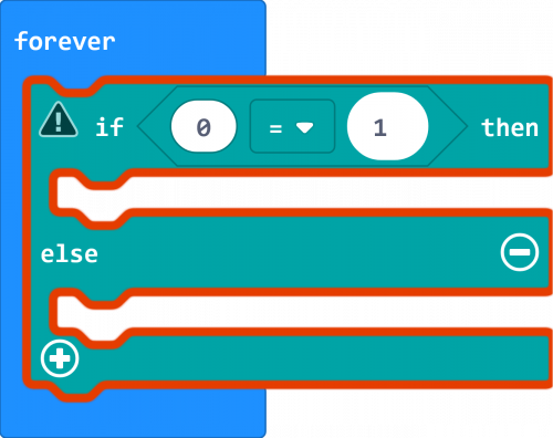
Go to the Pins, drag and drop the digital read pin(P0) block into if (0)=(1) then...else... block, replacing the “0 ” field.
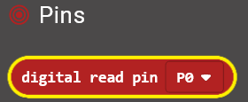
Look back at the connection diagram, we connect the signal pin to P0. So we select the P0 in the code; and input 1, which means input a HIGH level to the pin so as to lit the LED.
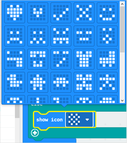
And then again go to Basic and drag the show icon block beneath the logic block you just made. Otherwise show another icon.
You can click the drop-down triangle to scroll down to choose the icon you want.
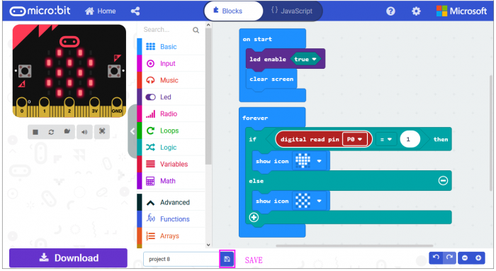
After completing the code, let's move on to name and download the program we’ve written.
Run Code on Micro:bit
Connect the micro:bit to your computer with a micro USB cable. You can right-click the microbit HEX file to send to your micro:bit main board.
![]()
Powered the microbit with batteries, press the button, the micro:bit main board will show a heart shape icon; release the button, show another icon.
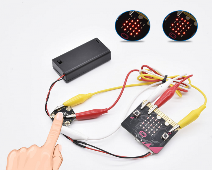
Project 9: Capacitive Touch
Overview
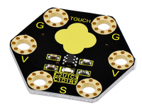
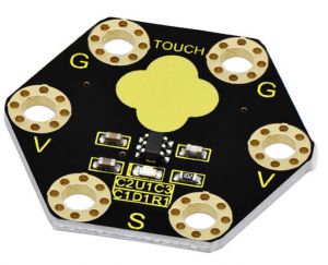
keyestudio Capacitive Touch Module For BBC micro:bit
This keyestudio capacitive touch module is fully compatible with micro:bit control board.
There are total 6 rings on the module. Note that two G rings, two V rings and two S rings are separately connected. G for ground; V for 3V; S for signal pin(0 1 2).
It mainly uses touch detection IC, which is a digital signal output device.
The touch detection IC is designed to replace the traditional button with a variable area key, featuring low power consumption and wide operating voltage.
When power on the module, it needs a stabilization time of about 0.5 sec. During this time period, do not touch the keypad. At this time, all functions are disabled, and self-calibration is always performed. No touching the key, the recalibration period is about 4.0sec.
Capacitive touch sensors are used in many devices such as laptop trackpads, digital audio players, computer displays, mobile phones, mobile devices, tablets and others.
When using, connect the module to micro:bit control board using Crocodile clip line.
When touch the sensing area, input HIGH level signal to micro:bit signal end, LED on the module will turn on; or else, turn off.
Technical Parameters
- Working voltage: DC 3.0-3.3V
- Output Signal: Digital
- Dimensions: 31mm*27mm*6.5mm
- Weight: 1.8g
- Environmental attributes: ROHS
Hardware Required:
- Micro:bit main board *1
- Keyestudio Tactile Button Module for micro:bit *1
- Alligator clip cable *3
- USB cable *1
Connection Diagram
Connect the keyestudio Capacitive Touch Module to micro:bit main board with 3 Alligator clip cables. Ring S to P0, V to 3V, G to GND.
Connect the micro:bit to your computer with a micro USB cable.

Coding
So now let's move to coding. Let us see how we can code the microbit LED matrix show icons with button module. Below are some steps to follow.
Open the https://makecode.micro:bit.org/#editor to write your code.
Microsoft MakeCode is actually a platform that allows us to code for a micro:bit, and also provides an interactive simulator where we can debug and run our code, and will be able to see what to expect out right there on the site.
Go to MakeCode and choose My Projects and click on New Projects.
If you want to see the codes behind, then you can click on JavaScript and it will display JavaScript code there in IDE.

Capacitive Touch Controlling LED
Let's get started and show icons on micro:bit using button control. To do so, you just need to go to Basic and scroll down to see an on start and clear screen block.
Now drag and drop, and go to Led and click more to drag out the block led enable(true) into on start block.

And again go to Basic and drag the forever block beneath the on start block you just made.
Now drag and drop, and go to Logic and search for if (true) then...else...block.
Drag this logic conditional block into forever block.
And add a comparison block to the logic conditional block.

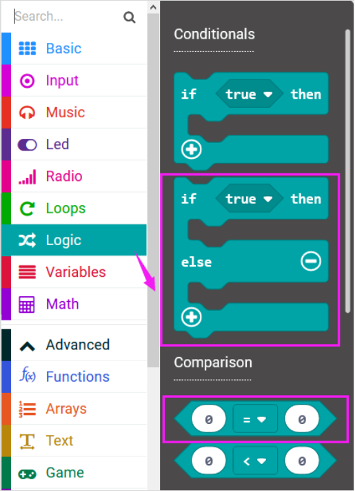
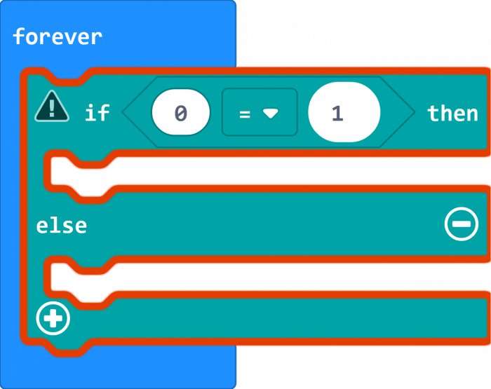
Go to the Pins, drag and drop the digital read pin(P0) block into if (0)=(1) then...else... block, replacing the “0 ” field.

Look back at the connection diagram, we connect the signal pin to P0. So we select the P0 in the code; and input 1, which means input a HIGH level to the pin so as to lit the LED.
And then again go to Basic and drag the show icon block beneath the logic block you just made. Otherwise show another icon.

You can click the drop-down triangle to scroll down to choose the icon you want.
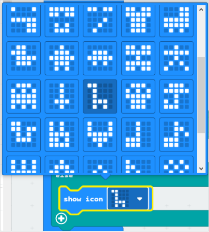
After completing the code, let's move on to name and download the program we’ve written.
![]()
Project 10: Ambient Light
Overview
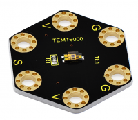
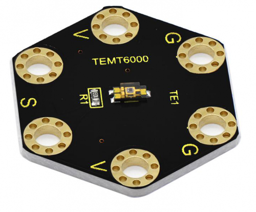
keyestudio TEMT6000 Light Module For BBC micro:bit
This keyestudio TEMT6000 light module is fully compatible with micro:bit control board.
This module is mainly composed of a highly sensitive visible photocell (NPN type) triode, which can magnify the captured tiny light illumination changes by about 100 times, and is easily recognized by the microcontroller for AD conversion.
Its response to visible light illumination is similar to that of the human eye, so that can detect the intensity of ambient light.
There are total 6 rings on the module. Note that two G rings, two V rings and two S rings are connected. G for ground; V for 3V; S for signal pin(0 1 2).
It is an analog signal output device.
When using, connect the module to micro:bit control board using Crocodile clip line.
You can use it to detect the ambient light intensity by reading the analog value of signal pin.
Technical Parameters
Working voltage: DC 3.0-3.3V
Output Signal: Analog signal
Dimensions: 31mm*27mm*2.5mm
Weight: 1.7g
Environmental attributes: ROHS
Hardware Required:
Micro:bit main board *1
Keyestudio TEMT6000 Light Module for micro:bit *1
USB cable *1
Connection Diagram
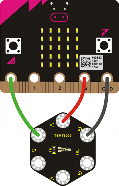
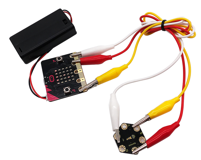
Connect the keyestudio TEMT6000 Light Module to micro:bit main board with 3 Alligator clip cables. Ring S to P0, V to 3V, G to GND.
Connect the micro:bit to your computer with a micro USB cable.
Coding
So now let's move to coding. Let us see how we can code and display the analog value of ambient light. Below are some steps to follow.
Open the https://makecode.micro:bit.org/#editor to write your code.
Microsoft MakeCode is actually a platform that allows us to code for a micro:bit, and also provides an interactive simulator where we can debug and run our code, and will be able to see what to expect out right there on the site.
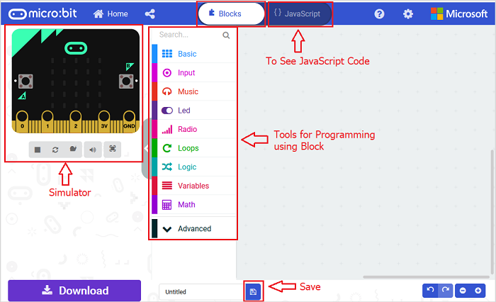
Go to MakeCode and choose My Projects and click on New Projects.
If you want to see the codes behind, then you can click on JavaScript and it will display JavaScript code there in IDE.
Analog Value Display
Let's get started and display the analog value of ambient light on our micro:bit. To do so, you just need to go to Basic and scroll down to see an on start block.
Now drag and drop, and again go to Basic and click more to drag the block clear screen out; means turn off all LEDs.
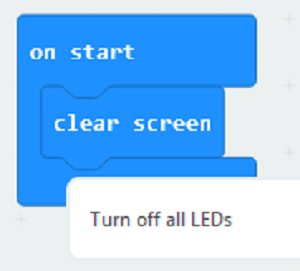
Now go to the Basic and scroll down to see a forever and show number(0) block. Drag the forever block beneath the on start block. And drag the show number(0) block into the forever block.
Go to Pins, drag and drop the block analog read pin(P0) into show number(0) block, replacing the “0” field.
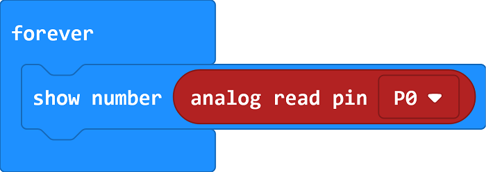
At this moment, we can add a pause (ms) block into the block just made. This delay period is in milliseconds, so if you want the value display as fast, change the value, try 100ms.
Next, we go to Serial, drag and drop the block serial write value(x)=(0)]
In this way it can write the brightness value to the serial port and show it on monitor.
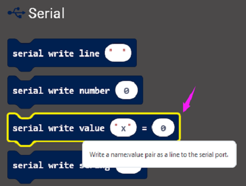
Change the “x” to brightness and duplicate the block analog read pin(P0) to replace the the “0” field.
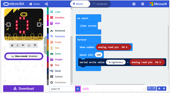
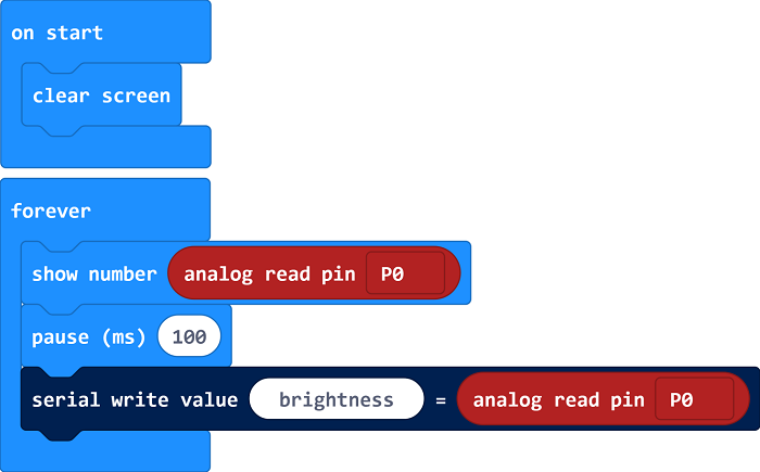
After completing the code, let's move on to name and download the program we’ve written.

Source Code:
Run Code on Micro:bit
Connect the micro:bit to your computer with a micro USB cable. You can right-click the microbit HEX file to send to your micro:bit main board.
You should see the LED matrix show the scrolling number. Or you can open the serial monitor of Arduino IDE to see the analog value of light intensity.
The stronger the ambient light intensity, the greater the analog value is.
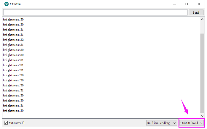
Note: the baud rate of micro:bit is defaulted by 115200.
Project 11: PIR Motion
Overview
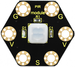
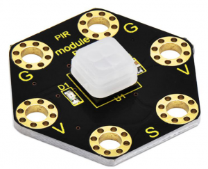
keyestudio PIR Motion Module For BBC micro:bit
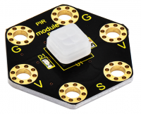
This keyestudio PIR motion module is fully compatible with micro:bit control board.
It is mainly composed of a digital pyroelectric infrared sensor, which is a digital signal output device.
This sensor has built-in filters, strong anti-interference, low voltage and micro power consumption. The detection distance of the module is 3-5 meters.
The detection angle in the horizontal direction is less than 80°; the detection angle in the vertical direction is less than 55°
There are total 6 rings on the module. Note that two G rings, two V rings and two S rings are separately connected. G for ground; V for 3V; S for signal pin(0 1 2).
When using, connect the module to micro:bit control board using Crocodile clip line.
Once detecting someone moving nearby, the signal pin of micro:bit main board will input HIGH level; LED on the module lights.
Technical Parameters
- Working voltage: DC 3.0-3.3V
- Working current: 100mA
- Maximum power: 0.5W
- Output signal: digital signal
- Detection distance: 3-5 meters
- Operating temperature range: -30℃~ +80℃
- Detection angle: less than 80°in the horizontal direction and less than 55° in the vertical direction
- Dimensions: 31mm*27mm*6mm
- Weight: 2g
- Environmental attributes: ROHS
Hardware Required:
- Micro:bit main board *1
- Keyestudio PIR Motion Module for micro:bit *1
- Alligator clip cable *3
- USB cable *1
Connection Diagram
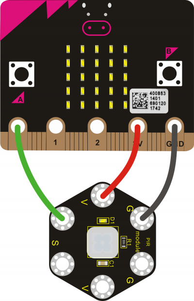
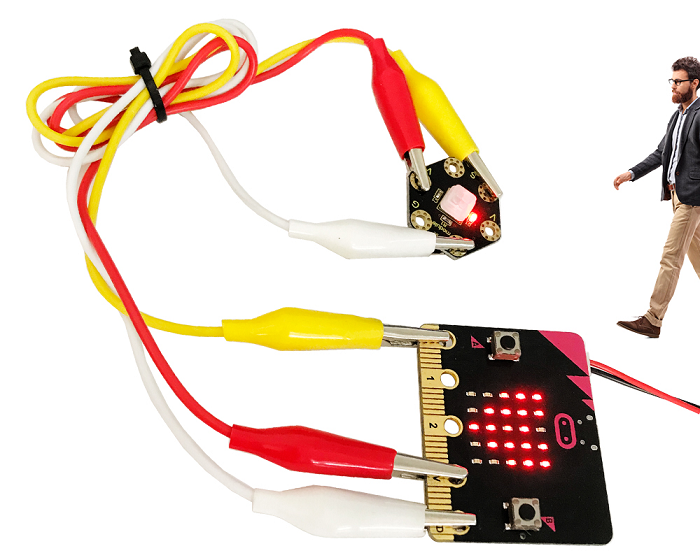
Connect the keyestudio PIR Motion Module to micro:bit main board with 3 Alligator clip cables. Ring S to P0, V to 3V, G to GND.
Connect the micro:bit to your computer with a micro USB cable.
Coding
So now let's move to coding. Let us see how we can code the micro:bit and PIR motion sensor to detect whether there is someone moving nearby.
Below are some steps to follow:
Open the https://makecode.micro:bit.org/#editor to write your code.
Microsoft MakeCode is actually a platform that allows us to code for a micro:bit, and also provides an interactive simulator where we can debug and run our code, and will be able to see what to expect out right there on the site.
Go to MakeCode and choose My Projects and click on New Projects.
If you want to see the codes behind, then you can click on JavaScript and it will display JavaScript code there in IDE.

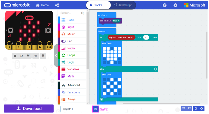
PIR Motion Sensing
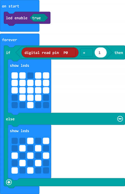
Let's get started and show icons on micro:bit when detects someone moving nearby. To do so, you just need to go to Basic and scroll down to see an on start block.
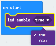
Now drag and drop, and go to Led and click more to drag out the block led enable(true) into on start block.
And again go to Basic and drag the forever block beneath the on start block you just made.
Now drag and drop, and go to Logic and search for if (true) then...else...block.
Drag this logic conditional block into forever block.
And add a comparison block to the logic conditional block.

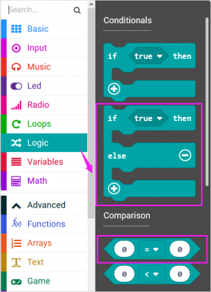
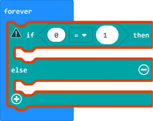
Go to the Pins, drag and drop the digital read pin(P0) block into if (0)=(1) then...else...block, replacing the “0” field.
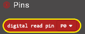
Look back at the connection diagram, we connect the signal pin to P0. So we select the P0 in the code; and input 1, which means input a HIGH level to the pin so as to lit the LED.
And then again go to Basic and drag the show leds block beneath the logic block you just made. Otherwise show another icon.
You can draw an image on the LED screen as you wish.
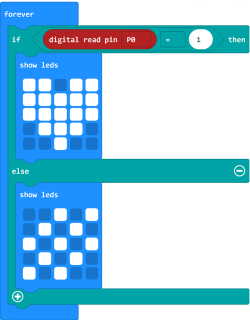
After completing this step micro:bit will restart itself and run the code. It will display icons on the simulator. Quite easy? Yeah, quite easy. So let's move on and name and download the program we’ve written.

Run Code on Micro:bit
Connect the micro:bit to your computer with a micro USB cable.
You can right-click the microbit HEX file to send to your micro:bit main board.
![]()
When detecting someone moving nearby, the LED matrix on the micro:bit main board will show a heart shape icon, and led on the PIR module lights.
Or else, it will show another image and led turns off.
Project 12: Microphone
Overview
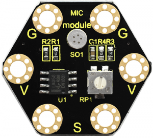
keyestudio Microphone Module For BBC micro:bit
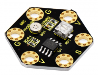
This keyestudio microphone module is fully compatible with micro:bit control board. It is a sound detection device, an analog signal output device.
It is mainly composed of a MIC head, a LM358D chip and a potentiometer.
When the microphone detects sound, and converts it into a voltage signal; then amplifies it through the LM358D chip.
The potentiometer is used to adjust the signal amplification.
There are total 6 rings on the module. Note that two G rings, two V rings and two S rings are separately connected. G for ground; V for 3V; S for signal pin(0 1 2).
We can work out the sound volume by reading the analog value of signal end.
When using, connect the module to micro:bit control board using Crocodile clip line.
Technical Parameters
- Working voltage: DC 3.0-3.3V
- Output signal: Analog signal
- Dimensions: 31mm*27mm*4mm
- Weight: 2g
- Environmental attributes: ROHS
Hardware Required:
- Micro:bit main board *1
- Keyestudio Microphone Module for micro:bit *1
- Alligator clip cable *3
- USB cable *1
Connection Diagram
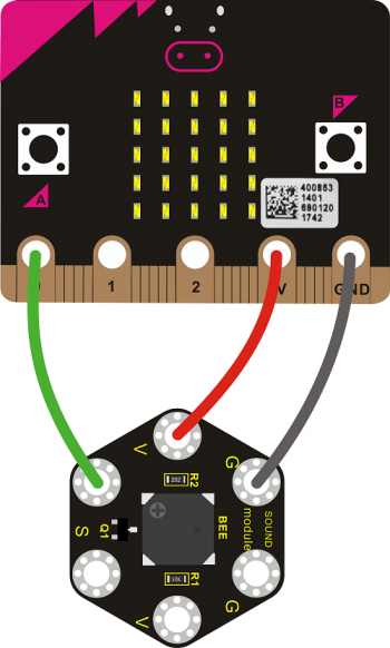
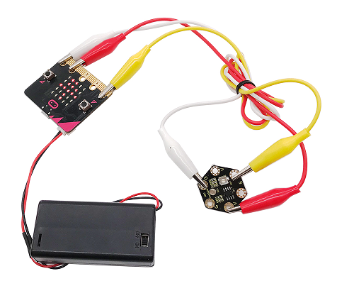
Connect the keyestudio Microphone Module to micro:bit main board with 3 Alligator clip cables. Ring S to P0, V to 3V, G to GND.
Connect the micro:bit to your computer with a micro USB cable.
Coding
So now let's move to coding. Let us see how we can code and display the analog value of microphone sound. Below are some steps to follow.
Open the https://makecode.micro:bit.org/#editor to write your code.
Microsoft MakeCode is actually a platform that allows us to code for a micro:bit, and also provides an interactive simulator where we can debug and run our code, and will be able to see what to expect out right there on the site.
Go to MakeCode and choose My Projects and click on New Projects.
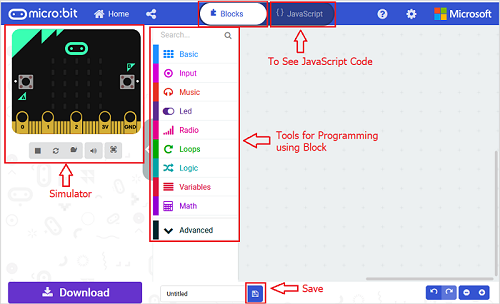
If you want to see the codes behind, then you can click on JavaScript and it will display JavaScript code there in IDE.
Analog Value Display
Let's get started and display the analog value of microphone sound on micro:bit. To do so, you just need to go to Basic and scroll down to see an on start block.
Now drag and drop, and again go to Basic and click more to drag the block clear screen out; means turn off all LEDs.

Now go to the Basicand scroll down to see a forever and show number(0) block. Drag the forever block beneath the on start block. And drag the show number(0) block into the forever block.
Go to Pins , drag and drop the block analog read pin(P0) into show number(0) block, replacing the “0” field.
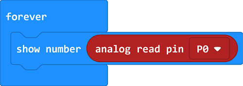
Next, we go to Serial, drag and drop the block serial write value(x)=(0)
In this way it can write the sound value to the serial port and show it on monitor.
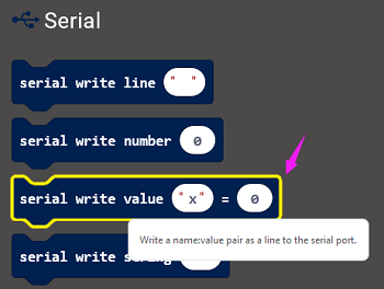
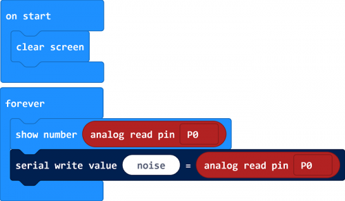
Change the “x ” to noise and duplicate the block analog read pin(P0) to replace the “0” field.
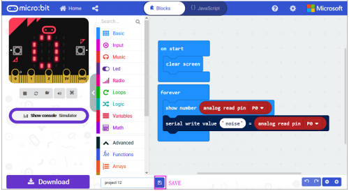
After completing the code, let's move on to name and download the program we’ve written.
![]()
Source Code:
Run Code on Micro:bit
Connect the micro:bit to your computer with a micro USB cable.
You can right-click the microbit HEX file to send to your micro:bit main board.
![]()
You should see the LED matrix show the scrolling digit. Or you can open the serial monitor of Arduino IDE to see the analog value of sound volume.
The louder the sound, the greater the analog value is.
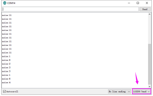
Note: the baud rate of micro:bit is defaulted by 115200.
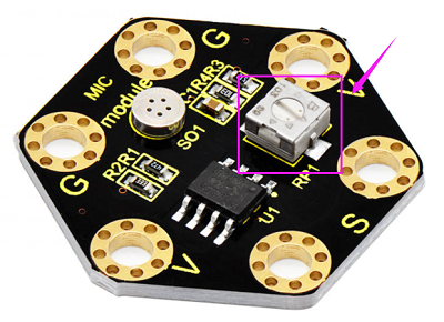
Pay close attention that you can turn the potentiometer on the module to adjust the sound magnification, which also will enlarge the analog value.
== Project 13: Buzzer ==
Overview
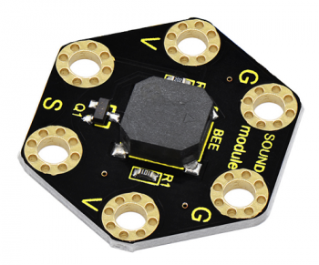
keyestudio Passive Buzzer Module For BBC micro:bit
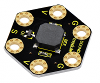
This keyestudio passive buzzer is fully compatible with micro:bit control board.
It is mainly composed of a passive buzzer without oscillation circuit. It cannot be actuated by itself, but by external pulse frequencies.
Different frequencies produce different sounds. Even can code the melody of a song.
There are total 6 rings on the module. Note that two G rings, two V rings and two S rings are connected. G for ground; V for 3V; S for signal pin(0 1 2).
When using, connect the module to micro:bit control board using Crocodile clip line.
Technical Parameters
- Working voltage: DC 3.0-3.3V
- Output signal: Digital signal (square wave)
- Dimensions: 31mm*27mm*4.5mm
- Weight: 2.3g
- Environmental attributes: ROHS
Hardware Required:
- Micro:bit main board *1
- Keyestudio Passive Buzzer Module for micro:bit *1
- Alligator clip cable *3
- USB cable *1
Connection Diagram
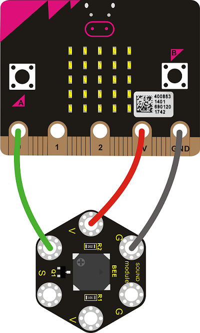
Connect the keyestudio Passive Buzzer Module to micro:bit main board with 3 Alligator clip cables. Ring S to P0, V to 3V, G to GND.
Coding
So now let's move to coding. Let us see how we can code the buzzer play tune. Below are some steps to follow.
Open the https://makecode.micro:bit.org/#editor to write your code.
Microsoft MakeCode is actually a platform that allows us to code for a micro:bit, and also provides an interactive simulator where we can debug and run our code, and will be able to see what to expect out right there on the site.
Go to MakeCode and choose My Projects and click on New Projects.
If you want to see the codes behind, then you can click on JavaScript and it will display JavaScript code there in IDE.
Buzzer
Let's get started and code the buzzer play a tone. To do so, you just need to go to Basic and scroll down to see an on start block.
Now drag and drop, and again go to Basic and click more to drag the block clear screen out; means turn off all LEDs.

Now go to the Basic and scroll down to see a forever block. Drag the forever block beneath the on start block.
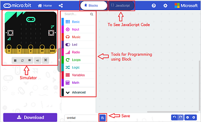
Go to Loops, drag and drop the while(true)...do block and drag out the Comparison statement from Logic.
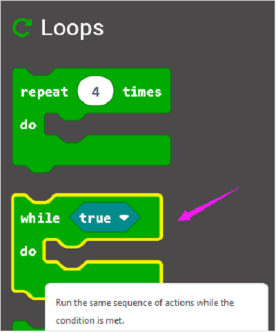
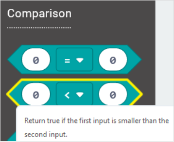
In the forever block, we set to output 2 kinds of square wave of different frequencies, so as to output a tone of corresponding frequency.
First, set a variable to output 80 pulse square wave, with a period of 2 milliseconds, and the frequency is 500 Hz, so the passive buzzer outputs 500 Hz frequency sound for 160 milliseconds.
Then delay 100 milliseconds.
And set to output 100 pulse square wave, with a period of 4 milliseconds, and the frequency is 250Hz, so the passive buzzer outputs 250Hz frequency sound for 400 milliseconds.
Code 1:
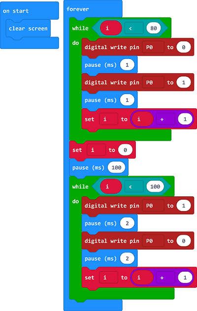
After completing the code, let's move on to name and download the program we’ve written.

Run Code on Micro:bit
Connect the micro:bit to your computer with a micro USB cable. You can right-click the microbit HEX file to send to your micro:bit main board.
Done sending the code 1 to micro:bit, the passive buzzer will alternately make two sounds.
Moreover, we can use the buzzer module to code a melody of a song.
Code 2:

Note:
If you drag the source code we provided to the Microsoft MakeCode Block editor https://makecode.micro:bit.org/#editor
Click the icon![]() , you can check the frequency of each tone as follows:
, you can check the frequency of each tone as follows:
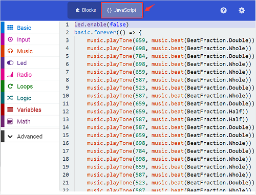
Result
Done sending the code 2 to micro:bit, the buzzer will play a song of Ode To Joy.
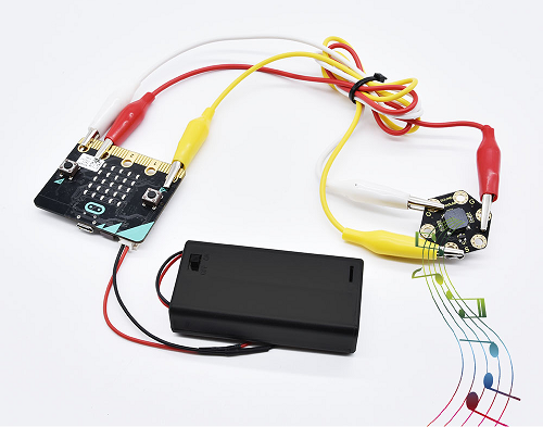
== Project 14: Two Lights ==
Overview
keyestudio Edge Connector IO Breakout Board For BBC micro:bit
It's what you've been waiting for, the keyestudio Edge Connector IO Breakout Board For BBC micro:bit.
Want to connect a bunch of sensors and modules to micro:bit development board? Try this keyestudio Edge Connector IO Breakout Board.
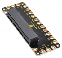
This breakout board has been designed to offer an easy way to connect additional circuits and hardware to the edge connector on the BBC micro:bit.
It provides an easy way of connecting circuits using Alligator clip lines.
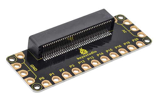
This edge connector offers access to a number of the BBC micro:bit processor pins, such as power IO (input/output) interface, connection pins P0、P1、P2、P3、P12、P13、P14、P15、P16、P19、P20 .
There are 2 kinds of power supply for the breakout board and micro:bit main board.
Direct to connect the battery case carried with batteries to micro:bit main board for powering;
Connect the golden rings 3V GND with alligator clip lines for power supply;
The breakout board also comes with 4 fixed holes at the edge, easy to mount on any other devices.
Specification
- Operating voltage: DC3.0-3.3V
- Dimensions: 89mm*33mm*12mm
- Weight:14.8g

Hardware Required:
Micro:bit main board *1
keyestudio Edge Connector IO Breakout Board for micro:bit *1
Alligator clip cable *7
USB cable *1
Connection Diagram
Connect the keyestudio Passive Buzzer Module to micro:bit main board with 3 Alligator clip cables. Ring S to P0, V to 3V, G to GND.
Connect the micro:bit to your computer with a micro USB cable.
Coding
So now let's move to coding. Let us see how we can code the 2 LED modules flash. Below are some steps to follow.
Open the https://makecode.micro:bit.org/#editor to write your code.
Microsoft MakeCode is actually a platform that allows us to code for a micro:bit, and also provides an interactive simulator where we can debug and run our code, and will be able to see what to expect out right there on the site.
Go to MakeCode and choose My Projects and click on New Projects.
If you want to see the codes behind, then you can click on JavaScript and it will display JavaScript code there in IDE.

Light Flash
Let's get started and code the 2 light modules flash on. To do so, you just need to go to Basic and scroll down to see an on start block.
Now drag and drop, and go to Led and click more to drag out the block led enable(false) into on start block.

And again go to Basic and drag the forever block beneath the on start block you just made.
Go to the Pins, drag and drop the digital write pin(P0) to(0) block into forever block and duplicate it several times.

Look at the connection diagram , we separately connect the Red,Green, Blue pin to P1, P2, P3. The white LED’s signal pin to P0.
So we first set the white LED’s signal pin value to 1, which means input a HIGH level to turn on the white LED. Set to 0 to turn it off.
The RGB pins are active at LOW (record 0), which means set to 0 to turn on; so we can set the RGB pins to HIGH (record 1) to turn off.
If you want the LED flash as fast, add a pause block in millisecond, try 200ms.
Now we separately turn the white LED (P0) on for 1 second then off, followed by turn Red LED (P1) on for 1 second then off; turn Green LED (P2) on for 1 second then off; turn the Blue LED (P3) on for 1 second then off.
Project 12: Microphone
Overview
keyestudio Microphone Module For BBC micro:bit
This keyestudio microphone module is fully compatible with micro:bit control board. It is a sound detection device, an analog signal output device.
It is mainly composed of a MIC head, a LM358D chip and a potentiometer.
When the microphone detects sound, and converts it into a voltage signal; then amplifies it through the LM358D chip.
The potentiometer is used to adjust the signal amplification.
There are total 6 rings on the module. Note that two G rings, two V rings and two S rings are separately connected. G for ground; V for 3V; S for signal pin(0 1 2).
We can work out the sound volume by reading the analog value of signal end.
When using, connect the module to micro:bit control board using Crocodile clip line.
Technical Parameters
- Working voltage: DC 3.0-3.3V
- Output signal: Analog signal
- Dimensions: 31mm*27mm*4mm
- Weight: 2g
- Environmental attributes: ROHS
Hardware Required:
- Micro:bit main board *1
- Keyestudio Microphone Module for micro:bit *1
- Alligator clip cable *3
- USB cable *1
Connection Diagram
Connect the keyestudio Microphone Module to micro:bit main board with 3 Alligator clip cables. Ring S to P0, V to 3V, G to GND.
Connect the micro:bit to your computer with a micro USB cable.

Coding
So now let's move to coding. Let us see how we can code and display the analog value of microphone sound. Below are some steps to follow.
Open the https://makecode.micro:bit.org/#editor to write your code.
Microsoft MakeCode is actually a platform that allows us to code for a micro:bit, and also provides an interactive simulator where we can debug and run our code, and will be able to see what to expect out right there on the site.
Go to MakeCode and choose My Projects and click on New Projects.
If you want to see the codes behind, then you can click on JavaScript and it will display JavaScript code there in IDE.

Analog Value Display
Let's get started and display the analog value of microphone sound on micro:bit. To do so, you just need to go to Basic and scroll down to see an on start block.
Now drag and drop, and again go to Basic and click more to drag the block clear screen out; means turn off all LEDs.

Now go to the Basicand scroll down to see a forever and show number(0) block. Drag the forever block beneath the on start block. And drag the show number(0) block into the forever block.
Go to Pins , drag and drop the block analog read pin(P0) into show number(0) block, replacing the “0” field.

Next, we go to Serial, drag and drop the block serial write value(x)=(0)
In this way it can write the sound value to the serial port and show it on monitor.

Change the “x ” to noise and duplicate the block analog read pin(P0) to replace the “0” field.

After completing the code, let's move on to name and download the program we’ve written.
![]()
Source Code:

Run Code on Micro:bit
Connect the micro:bit to your computer with a micro USB cable.
You can right-click the microbit HEX file to send to your micro:bit main board.
![]()
You should see the LED matrix show the scrolling digit. Or you can open the serial monitor of Arduino IDE to see the analog value of sound volume.
The louder the sound, the greater the analog value is.


Note: the baud rate of micro:bit is defaulted by 115200.
Pay close attention that you can turn the potentiometer on the module to adjust the sound magnification, which also will enlarge the analog value.

Project 13: Buzzer
Overview
keyestudio Passive Buzzer Module For BBC micro:bit
This keyestudio passive buzzer is fully compatible with micro:bit control board.
It is mainly composed of a passive buzzer without oscillation circuit. It cannot be actuated by itself, but by external pulse frequencies.
Different frequencies produce different sounds. Even can code the melody of a song.
There are total 6 rings on the module. Note that two G rings, two V rings and two S rings are connected. G for ground; V for 3V; S for signal pin(0 1 2).
When using, connect the module to micro:bit control board using Crocodile clip line.
Technical Parameters
Working voltage: DC 3.0-3.3V
Output signal: Digital signal (square wave)
Dimensions: 31mm*27mm*4.5mm
Weight: 2.3g
Environmental attributes: ROHS
Hardware Required:
Micro:bit main board *1
Keyestudio Passive Buzzer Module for micro:bit *1
USB cable *1
Connection Diagram
Connect the keyestudio Passive Buzzer Module to micro:bit main board with 3 Alligator clip cables. Ring S to P0, V to 3V, G to GND.

Coding
So now let's move to coding. Let us see how we can code the buzzer play tune. Below are some steps to follow.
Open the https://makecode.micro:bit.org/#editor to write your code.
Microsoft MakeCode is actually a platform that allows us to code for a micro:bit, and also provides an interactive simulator where we can debug and run our code, and will be able to see what to expect out right there on the site.
Go to MakeCode and choose My Projects and click on New Projects.
If you want to see the codes behind, then you can click on JavaScript and it will display JavaScript code there in IDE.

Buzzer
Let's get started and code the buzzer play a tone. To do so, you just need to go to Basic and scroll down to see an on start block.
Now drag and drop, and again go to Basic and click more to drag the block clear screen out; means turn off all LEDs.

Now go to the Basic and scroll down to see a forever block. Drag the forever block beneath the on start block.
Go to Loops, drag and drop the while(true)...do block and drag out the Comparison statement from Logic.


In the forever block, we set to output 2 kinds of square wave of different frequencies, so as to output a tone of corresponding frequency.
First, set a variable to output 80 pulse square wave, with a period of 2 milliseconds, and the frequency is 500 Hz, so the passive buzzer outputs 500 Hz frequency sound for 160 milliseconds.
Then delay 100 milliseconds.
And set to output 100 pulse square wave, with a period of 4 milliseconds, and the frequency is 250Hz, so the passive buzzer outputs 250Hz frequency sound for 400 milliseconds.
Code 1:

After completing the code, let's move on to name and download the program we’ve written.

Run Code on Micro:bit
Connect the micro:bit to your computer with a micro USB cable. You can right-click the microbit HEX file to send to your micro:bit main board.
Done sending the code 1 to micro:bit, the passive buzzer will alternately make two sounds.
Moreover, we can use the buzzer module to code a melody of a song.
Code 2:

Note:
If you drag the source code we provided to the Microsoft MakeCode Block editor https://makecode.micro:bit.org/#editor
Click the icon![]() , you can check the frequency of each tone as follows:
, you can check the frequency of each tone as follows:

Result
Done sending the code 2 to micro:bit, the buzzer will play a song of Ode To Joy.

Project 14: Two Lights
Overview
keyestudio Edge Connector IO Breakout Board For BBC micro:bit
It's what you've been waiting for, the keyestudio Edge Connector IO Breakout Board For BBC micro:bit.
Want to connect a bunch of sensors and modules to micro:bit development board? Try this keyestudio Edge Connector IO Breakout Board.
This breakout board has been designed to offer an easy way to connect additional circuits and hardware to the edge connector on the BBC micro:bit.
It provides an easy way of connecting circuits using Alligator clip lines.

This edge connector offers access to a number of the BBC micro:bit processor pins, such as power IO (input/output) interface, connection pins P0、P1、P2、P3、P12、P13、P14、P15、P16、P19、P20 .
There are 2 kinds of power supply for the breakout board and micro:bit main board.
Direct to connect the battery case carried with batteries to micro:bit main board for powering;
Connect the golden rings 3V GND with alligator clip lines for power supply;
The breakout board also comes with 4 fixed holes at the edge, easy to mount on any other devices.
Specification
- Operating voltage: DC3.0-3.3V
- Dimensions: 89mm*33mm*12mm
- Weight:14.8g
Hardware Required:
- Micro:bit main board *1
- keyestudio Edge Connector IO Breakout Board for micro:bit *1
- Alligator clip cable *7
- USB cable *1
Connection Diagram
Connect the keyestudio Passive Buzzer Module to micro:bit main board with 3 Alligator clip cables. Ring S to P0, V to 3V, G to GND.
Connect the micro:bit to your computer with a micro USB cable.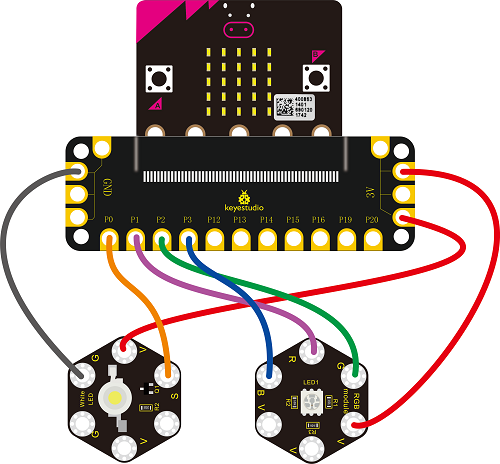
Coding
So now let's move to coding. Let us see how we can code the 2 LED modules flash. Below are some steps to follow.
Open the https://makecode.micro:bit.org/#editor to write your code.
Microsoft MakeCode is actually a platform that allows us to code for a micro:bit, and also provides an interactive simulator where we can debug and run our code, and will be able to see what to expect out right there on the site.
Go to MakeCode and choose My Projects and click on New Projects.
If you want to see the codes behind, then you can click on JavaScript and it will display JavaScript code there in IDE.
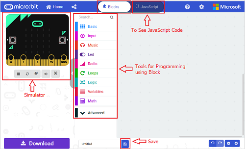
Light Flash
Let's get started and code the 2 light modules flash on. To do so, you just need to go to Basic and scroll down to see an on start block.
Now drag and drop, and go to Led and click more to drag out the block led enable(false) into on start block.
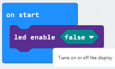
And again go to Basic and drag the forever block beneath the on start block you just made.
Go to the Pins, drag and drop the digital write pin(P0) to(0) block into forever block and duplicate it several times.
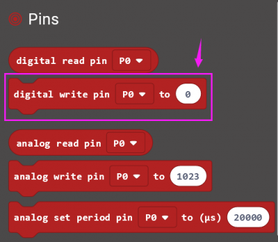
Look at the connection diagram , we separately connect the Red,Green, Blue pin to P1, P2, P3. The white LED’s signal pin to P0.
So we first set the white LED’s signal pin value to 1, which means input a HIGH level to turn on the white LED. Set to 0 to turn it off.
The RGB pins are active at LOW (record 0), which means set to 0 to turn on; so we can set the RGB pins to HIGH (record 1) to turn off.
If you want the LED flash as fast, add a pause block in millisecond, try 200ms.
Now we separately turn the white LED (P0) on for 1 second then off, followed by turn Red LED (P1) on for 1 second then off; turn Green LED (P2) on for 1 second then off; turn the Blue LED (P3) on for 1 second then off.
Code:

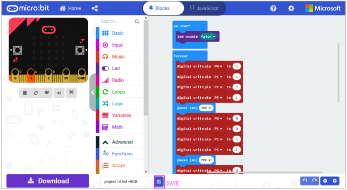
After completing the code, let's move on to name and download the program we’ve written.

Run Code on Micro:bit
Connect the micro:bit to your computer with a micro USB cable. You can right-click the microbit HEX file to send to your micro:bit main board.
The white LED module will turn on then off, followed by RGB turning on red, green and blue, with an interval of 200ms, alternately and circularly.
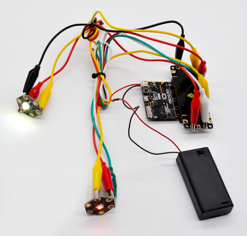
Project 15: Button Control Light
Overview
In the above projects, we’ve introduced each sensor module. We now combine those sensor modules to make interactive projects.
In this project, we would like to turn an LED on and off via a tactile button.
Hardware Required:
- Micro:bit main board *1
- Keyestudio Tactile Button Module for micro:bit *1
- keyestudio 1W LED Module for micro:bit *1
- Alligator clip cable *6
- USB cable *1
Connection Diagram
Insert firmly the micro:bit main board into keyestudio Edge Connector IO Breakout Board. Then connect the sensor module to micro:bit main board with alligator clip lines.
For keyestudio Tactile Button Module, connect Ring S to P0, V to 3V, G to GND.
For keyestudio 1W LED Module, connect Ring S to P1, V to 3V, G to GND.
Connect the micro:bit to your computer with a micro USB cable.
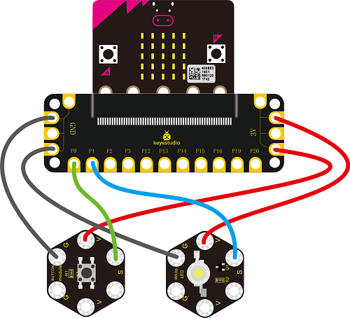
Coding
So now let's move to coding. Let us see how we can code the LED module on with tactile button module. Below are some steps to follow.
Open the https://makecode.micro:bit.org/#editor to write your code.
Microsoft MakeCode is actually a platform that allows us to code for a micro:bit, and also provides an interactive simulator where we can debug and run our code, and will be able to see what to expect out right there on the site.
Go to MakeCode and choose My Projects and click on New Projects.
If you want to see the codes behind, then you can click on JavaScript and it will display JavaScript code there in IDE.

Button Controlling LED
Let's get started and turn on LED via button control. To do so, you just need to go to Basic and scroll down to see an on start block.
Now drag and drop, and go to Led and click more to drag out the block led enable(false) into on start block.
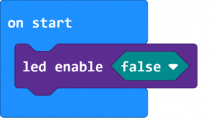
And again go to Basic and drag the forever block beneath the on start block you just made.
Now drag and drop, and go to Logic and search for if (true) then...else...block.
Drag this logic conditional block into forever block. And add a comparison block to the logic conditional block.
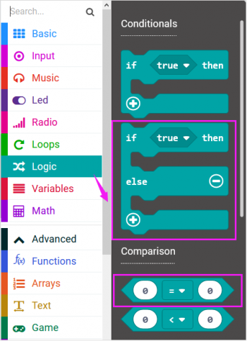
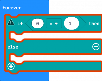
Go to the Pins, drag and drop the digital read pin(P0) block into if (0)=(1) then...else...block, replacing the “0” field.

Look back at the connection diagram, we connect the button’s signal pin to P0, LED’s signal pin to P1. So if set the P0 to 1, means the button is pressed, then set the P1 to 1, means input a HIGH level to lit the LED. Or else, do the contrary action, release the button to turn the led off.
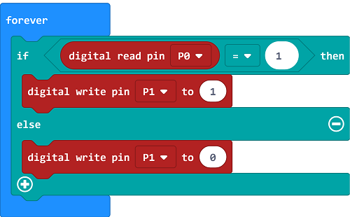
After completing the code, let's move on to name and download the program we’ve written.
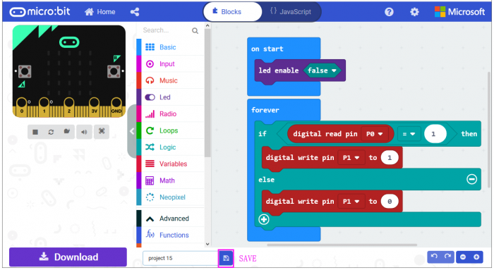

Source Code:
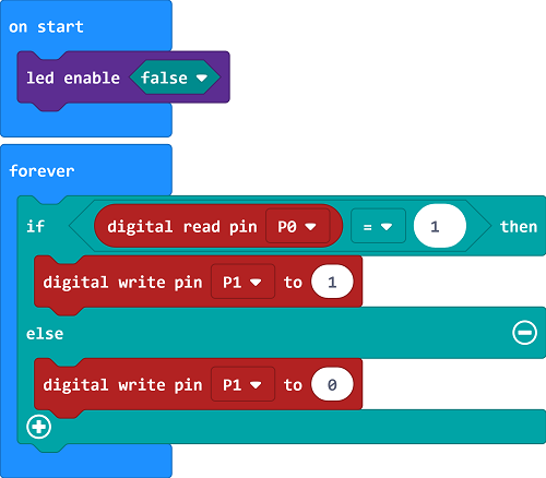
Run Code on Micro:bit
Connect the micro:bit to your computer with a micro USB cable. You can right-click the microbit HEX file to send to your micro:bit main board.

Powered on, press the button, the LED on the module should turn on; release the button, the LED turns off.
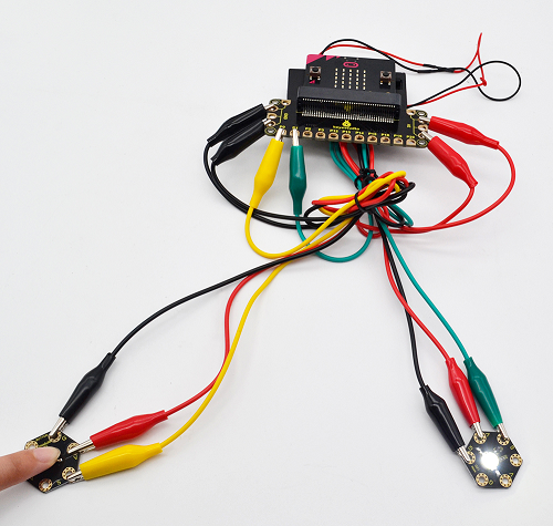
Project 16: RGB Colors
Overview
In the above projects, we’ve introduced each sensor module. We now combine those sensor modules to make interactive projects.
In this project, we are going to turn RGB LED alternately on red, green and blue via capacitive touch control.
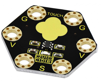
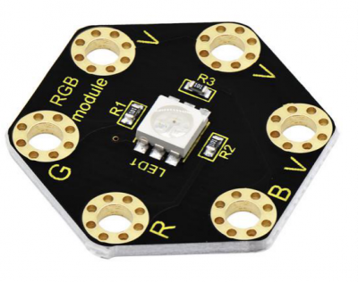
Hardware Required:
- Micro:bit main board *1
- Keyestudio Capacitive Touch Module for micro:bit *1
- keyestudio 5050 RGB Module for micro:bit *1
- Alligator clip cable *7
- USB cable *1
Connection Diagram
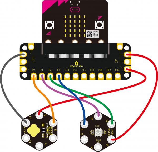
Insert firmly the micro:bit main board into keyestudio Edge Connector IO Breakout Board. Then connect the sensor module to micro:bit main board with alligator clip lines.
For keyestudio Capacitive Touch Module, connect Ring S to P0, V to 3V, G to GND.
For keyestudio RGB LED Module, connect Ring R to P1, G to P2, B to P3, V to 3V.
Connect the micro:bit to your computer with a micro USB cable.
Source Code
Open the https://makecode.micro:bit.org/#editor to write your code. Or can direct download and send the micro:bit.hex file to your micro:bit.

Code Explanation:
Look back at the connection diagram, we have connected the touch module to P0; Red, Green, Blue LED to P1, P2, P3.
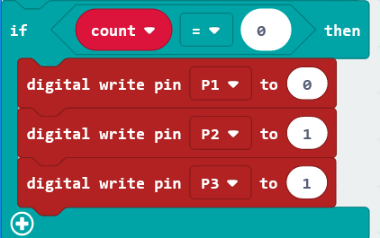
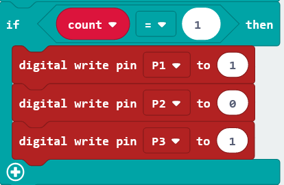
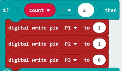
The RGB pins are active at LOW (record 0), which means set to 0 to turn on; so we can set the RGB pins to HIGH (record 1) to turn off.
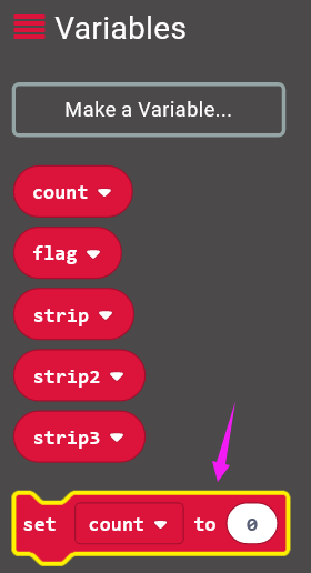
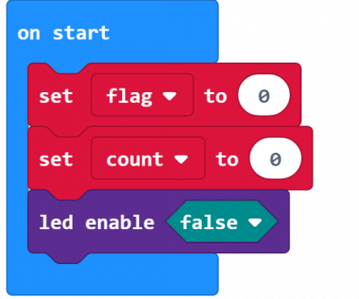
On start block, we initially set the variables flag and count block to 0;
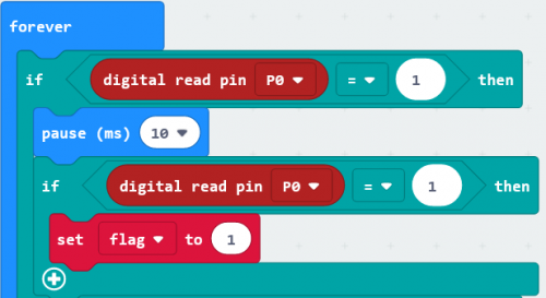
For the forever block, when detects the touch signal, we set the flag to 1, and add 10ms block for delay;
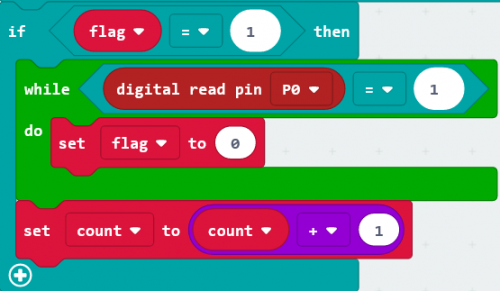
If flag equals to 1, run the flag to 0, set count plus 1;
If count equals to 0, run the action that RGB light turns on red;
If count equals to 1, run the action that RGB light turns on green;
If count equals to 2, run the action that RGB light turns on blue;
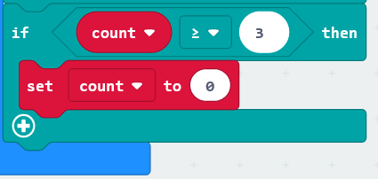
If count is greater than and equals to 3, then set the count to 0, run the action that RGB light turns on red;
Run Code on Micro:bit
Connect the micro:bit to your computer with a micro USB cable.
You can right-click the microbit HEX file to send to your micro:bit main board.

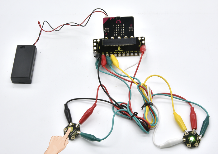
Done uploading the code, the RGB module will turn on red;
Tap the capacitive touch module with your finger, RGB will turn green; tap the touch area, turn on blue; tap again, turn on red. It will form a loop.
Project 17: Motion Alarm
Overview
In the above projects, we’ve introduced each sensor module. We now combine those sensor modules to make interactive projects.
In this project, you will learn how to trigger a buzzer alarm when detecting someone moving nearby.
Hardware Required:
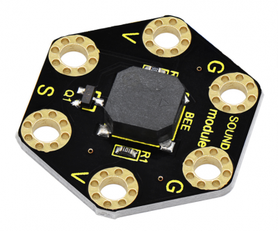
Micro:bit main board *1
Keyestudio Passive Buzzer Module for micro:bit *1
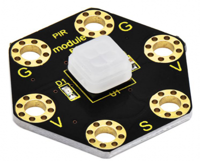
keyestudio PIR Motion Module for micro:bit *1
Alligator clip cable *6
USB cable *1
Connection Diagram
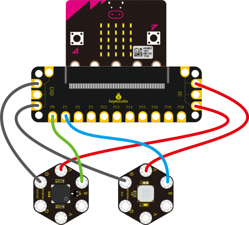
Insert firmly the micro:bit main board into keyestudio Edge Connector IO Breakout Board. Then connect the sensor module to micro:bit main board with alligator clip lines.
For keyestudio Passive Buzzer Module, connect Ring S to P0, V to 3V, G to GND.
For keyestudio PIR Motion Module, connect Ring S to P1, V to 3V, G to GND.
Connect the micro:bit to your computer with a micro USB cable.
Coding
So now let's move to coding. Let us see how we can code the passive buzzer alarm when PIR motion module detects someone moving nearby.
Below are some steps to follow.
Open the https://makecode.micro:bit.org/#editor to write your code.
Microsoft MakeCode is actually a platform that allows us to code for a micro:bit, and also provides an interactive simulator where we can debug and run our code, and will be able to see what to expect out right there on the site.
Go to MakeCode and choose My Projects and click on New Projects.
If you want to see the codes behind, then you can click on JavaScript and it will display JavaScript code there in IDE.

Motion Alarm
Let's get started with triggering the buzzer sound. To do so, you just need to go to Basic and scroll down to see an on start block.
Now drag and drop, and go to Led and click more to drag out the block led enable(false) into on start block.

And again go to Basic and drag the forever block beneath the on start block you just made.
Now drag and drop, and go to Logic and search for if (true) then...else...block.
Drag this logic conditional block into forever block. And add a comparison block to the logic conditional block.
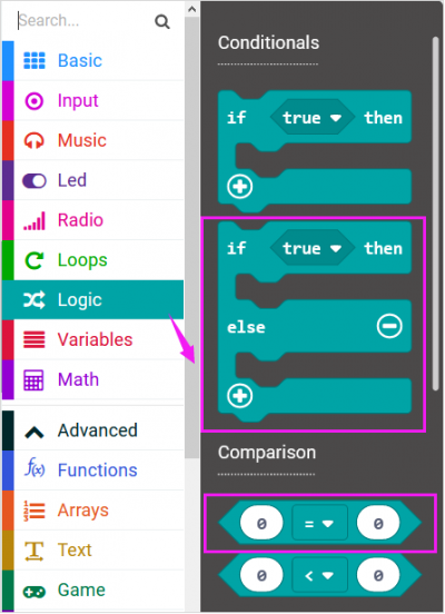

Go to the Pins, drag and drop the digital read pin(P0) block into if (0)=(1) then...else...block, replacing the “0” field.

Look back at the connection diagram, we connect the PIR motion sensor’s signal pin to P1. So change the pin P0 to P1.
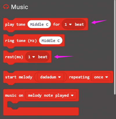
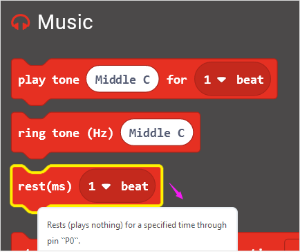
Then go to Music, drag and drop the block play tone(Middle C) for (1 beat) and rest(ms)(1 beat)
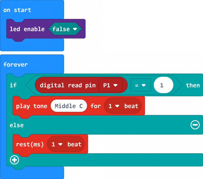
If the PIR motion sensor detects someone moving nearby, then the buzzer will play a tone (Middle C); otherwise, buzzer turns off.
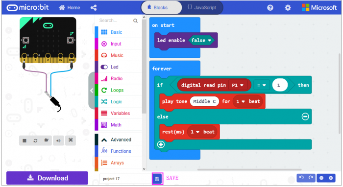
After completing the code, let's move on to name and download the program we’ve written.

Source Code:
Run Code on Micro:bit
Connect the micro:bit to your computer with a micro USB cable.
You can right-click the microbit HEX file to send to your micro:bit main board.

When someone is moving nearby, the built-in led on PIR motion sensor lights and buzzer will play a tone (Middle C). otherwise, the led is off and buzzer not sounds.
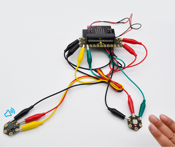
Project 18: Make a tone
Overview
In the above projects, we’ve introduced each sensor module. We now combine those sensor modules to make interactive projects.
In this project, you will learn how to make a buzzer play different tones based on the measured analog value of both ambient light and microphone sound.
Hardware Required:
Micro:bit main board *1
Keyestudio Passive Buzzer Module for micro:bit *1
Keyestudio TEMT6000 Light Module for micro:bit *1
Keyestudio Microphone Module for micro:bit *1
Alligator clip cable *9
USB cable *1
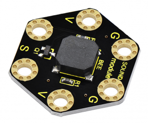
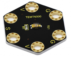
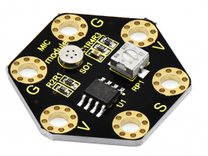
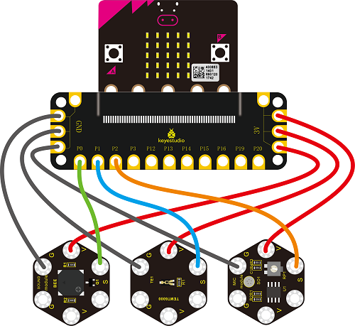
Connection Diagram
Insert firmly the micro:bit main board into keyestudio Edge Connector IO Breakout Board. Then connect the sensor module to micro:bit main board with alligator clip lines.
For keyestudio Passive Buzzer Module, connect Ring S to P0, V to 3V, G to GND.
For keyestudio TEMT6000 Light Module, connect Ring S to P1, V to 3V, G to GND.
For keyestudio Microphone Module, connect Ring S to P2, V to 3V, G to GND.
Connect the micro:bit to your computer with a micro USB cable.
Coding
So now let's move to coding. Let us see how we can code buzzer sound according to the analog value of both TEMT6000 light module and microphone module. Below are some steps to follow.
Open the https://makecode.micro:bit.org/#editor to write your code.
Microsoft MakeCode is actually a platform that allows us to code for a micro:bit, and also provides an interactive simulator where we can debug and run our code, and will be able to see what to expect out right there on the site.
Go to MakeCode and choose My Projects and click on New Projects.
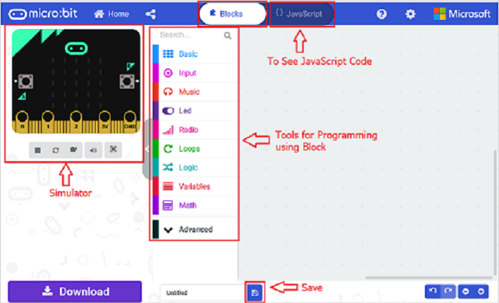
If you want to see the codes behind, then you can click on JavaScript and it will display JavaScript code there in IDE.
Ring Tone
Let's get started with playing tones. To do so, you just need to go to Basic and scroll down to see an on start block.
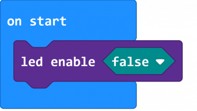
Now drag and drop, and go to Led and click more to drag out the block led enable(false) into on start block.
And again go to Basic and drag the forever block beneath the on start block you just made.
Next, go to Serial, drag and drop the block serial write value(x)=(0) into the forever block and duplicate once.
In this way it can write both brightness and sound value to the serial port and show it on monitor.
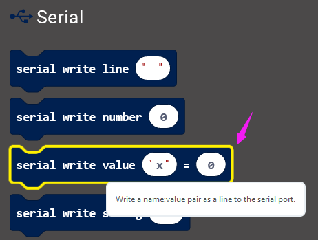
Separately change the “"x” to brightness and noise;
And drag out the block analog read pin(P0) from Pins to replace the “0” field.
According to the connection, microphone module’s signal pin is connected to P2; light module’s signal pin is connected to P1.
So we should write as follows:
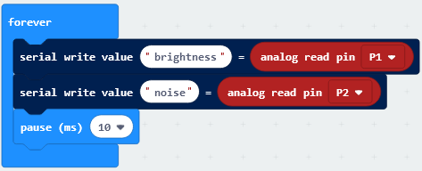
Now by followed, we are ready to add Loops and logic comparison function.
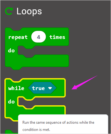
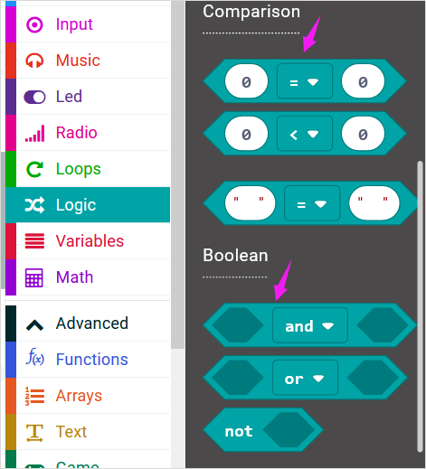
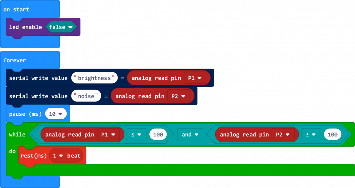
Supposed that both light and MIC analog value are smaller than or equal to 100, buzzer not beeps. How should we code?
First drag the while(true)...do block out from the Loops. Then add the Boolean and Comparison logic statements.
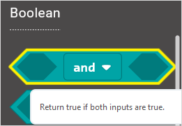
We duplicate and drag the Comparison block into Boolean block.

Then drag this block into the while(true)...do block, replacing the “true” field. And again duplicate the block analog read pin(P1) and the block analog read pin(P2) and drag them into the first input. Set both values smaller than and equal to 100.
While the condition is met, run the action that buzzer not beeps. We can go to drag the rest(ms)(1 beat) from Music into the while block just made.
Now we’ve set both light and MIC analog value are smaller than or equal to 100, buzzer not beeps. As shown below.
Furthermore, if we want to add several condition statements, be able to duplicate the while...do... block several times, and set to different input values to trigger buzzer ring different tones.
Have your try! Write the conditions as follows:
When the light analog value is greater than 100, and MIC analog value is smaller than or equal to 100, the buzzer will play a tone (Low B);
When the light analog value is smaller than or equal to 100, and MIC analog value is greater than 100, the buzzer will play a tone (Middle D);
When both light and MIC analog value are greater than 100, the buzzer play a tone (High E).
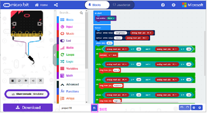
After completing the code, let's move on to name and download the program we’ve written.

Source Code:
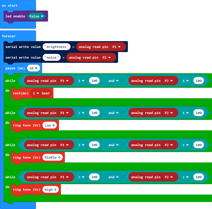
Run Code on Micro:bit
Connect the micro:bit to your computer with a micro USB cable. You can right-click the microbit HEX file to send to your micro:bit main board.
Done uploading the code, it measures the analog value of ambient light and microphone sound, which can be applied to make a buzzer sound.
When both light and MIC analog value are less than or equal to 100, buzzer not beeps;
When the light analog value is greater than 100, and MIC analog value is less than or equal to 100, the buzzer will play a tone (Low B);
When the light analog value is less than or equal to 100, and MIC analog value is greater than 100, the buzzer will play a tone (Middle D);
When both light and MIC analog value are greater than 100, the buzzer play a tone (High E).
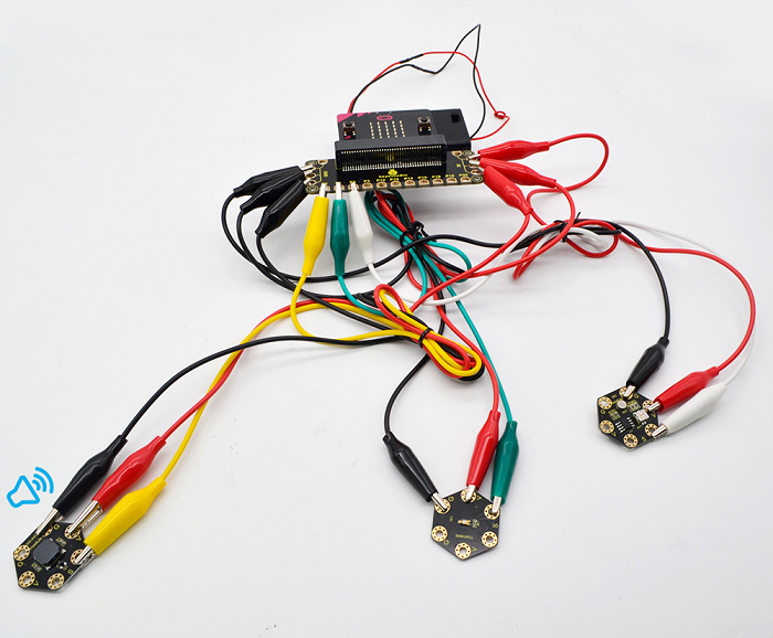
Project 19: Light Controlling RGB
Overview
In the above projects, we’ve introduced each sensor module. We now combine those sensor modules to make interactive projects.
In this project, you will learn how to trigger the RGB light shining colors based on the measured analog value of ambient light.
Hardware Required:
Micro:bit main board *1
Keyestudio TEMT6000 Light Module for micro:bit *1
Keyestudio 5050 RGB Module for micro:bit *1
Alligator clip cable *6
USB cable *1
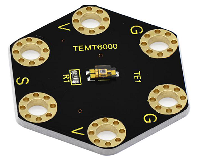
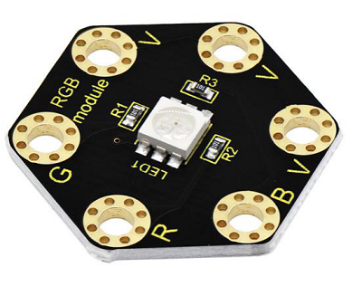
Connection Diagram
Insert firmly the micro:bit main board into keyestudio Edge Connector IO Breakout Board. Then connect the sensor module to micro:bit main board with alligator clip lines.
For keyestudio TEMT6000 Light Module, connect Ring S to P0, V to 3V, G to GND.
For keyestudio RGB LED Module, connect Ring R to P1, G to P2, B to P3, V to 3V.
Connect the micro:bit to your computer with a micro USB cable.
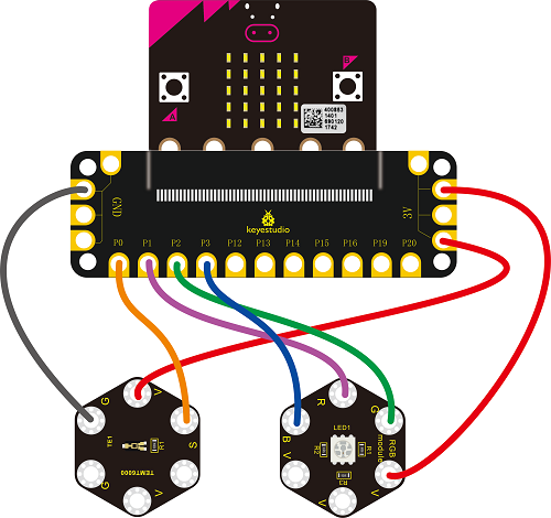
Coding
So now let's move to coding. Let us see how we can code the RGB flash on different colors in different analog value of ambient light.
Below are some steps to follow.
Open the https://makecode.micro:bit.org/#editor to write your code.
Microsoft MakeCode is actually a platform that allows us to code for a micro:bit, and also provides an interactive simulator where we can debug and run our code, and will be able to see what to expect out right there on the site.
Go to MakeCode and choose My Projects and click on New Projects.
If you want to see the codes behind, then you can click on JavaScript and it will display JavaScript code there in IDE.
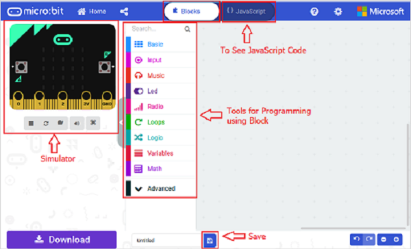
Light Controlling RGB
Let's get started with controlling RGB colors with light sensor. To do so, you just need to go to Basic and scroll down to see an on start block.
Now drag and drop, and go to Led and click moreto drag out the block led enable(false) into on start block.
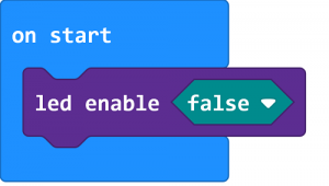
And again go to Basic and drag the foreverblock beneath the on start block you just made.
Then go to Variables, search for set (val) to (0) block and drag this block into forever block.
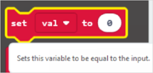
Go to Pins, drag and drop the block analog read pin(P0) into set (val) to (0) block, replacing the “0” field.
Look back at the connection diagram, we have connected the TEMT6000 light module to P0; Red, Green, Blue LED to P1, P2, P3.
The RGB pins are active at LOW (record 0), which means set to 0 to turn on; so we can set the RGB pins to HIGH (record 1) to turn off.
Now we set to print the light value to the serial port using the serial write number(0) block from Serial and set the logic conditionals.

Drag the val block from the Variables and drop into serial write number(0), replacing the “0” field.
Then add the logic conditionals block, we go to use light value to turn the RGB LED on.
Now go to Logic and search for if (true) then...block.
Drag this logic conditionals block beneath the serial write number block.
And add a comparison block to the logic conditional block, replacing (true).
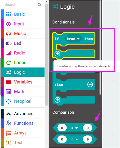
We set to if val value is less than or equal to 300, then turn Red LED on.
In other word, go to drag and duplicate digital write pin(P0) to (0) block twice. For RGB, separately set Pin1 to 0 (LOW, turn on); Pin2, Pin3 to 1 (HIHG, turn off)
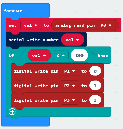
Furthermore, you can follow the same method to turn on the Green LED or Blue LED.
Set the light value is greater than 300 and less than 800, turn Green LED on;
Set the light value is greater than or equal to 800, turn Blue LED on.
After completing the code, let's move on to name and download the program we’ve written.

Source Code:
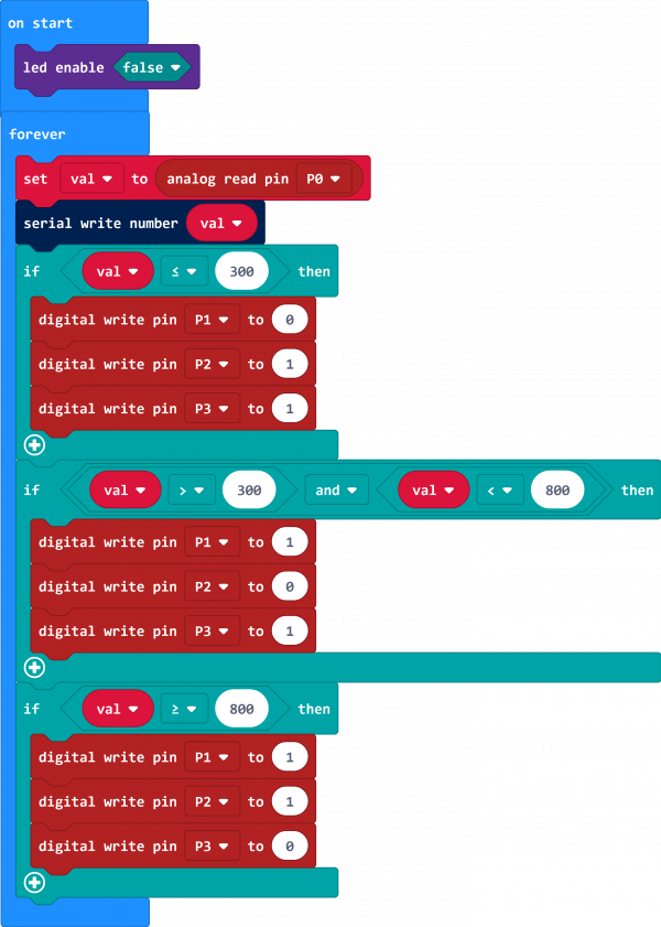
Run Code on Micro:bit
Connect the micro:bit to your computer with a micro USB cable. You can right-click the microbit HEX file to send to your micro:bit main board.
When analog value of ambient light is less than or equal to 300, RGB light turns on red; when analog value is greater than 300 and less than 800, RGB light turns on green; when analog value is greater than or equal to 800, RGB light turns on blue;
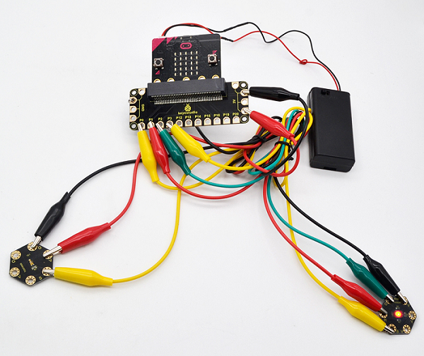
Project 20: Button Controlling Buzzer
Overview
In the above projects, we’ve introduced each sensor module. We now combine those sensor modules to make interactive projects.
In this project, you will learn how to make a buzzer play different tones with a tactile button.
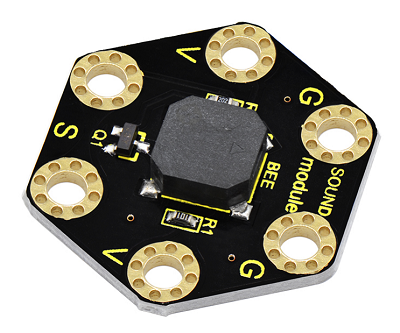
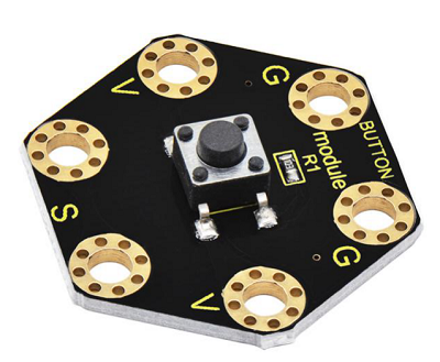
Hardware Required:
Micro:bit main board *1
Keyestudio Passive Buzzer Module for micro:bit *1
Keyestudio Tactile Button Module for micro:bit *1
Alligator clip cable *6
USB cable *1
Connection Diagram
Insert firmly the micro:bit main board into keyestudio Edge Connector IO Breakout Board. Then connect the sensor module to micro:bit main board with alligator clip lines.
For keyestudio Passive Buzzer Module, connect Ring S to P0, V to 3V, G to GND.
For keyestudio Tactile Button Module, connect Ring S to P1, V to 3V, G to GND.
Connect the micro:bit to your computer with a micro USB cable.
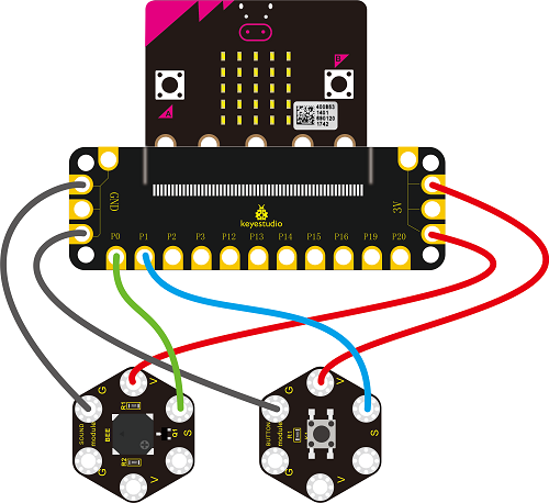
Source Code
Open the https://makecode.micro:bit.org/#editor to write your code. Or can direct download and send the micro:bit.hex file to your micro:bit.

Code Explanation:
On start block, we initially set the variables flag block to 0 and count block to 1;
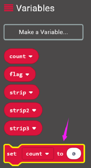
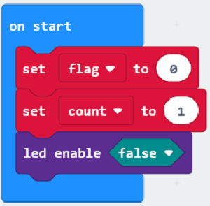
For the forever block, when detects the button signal, we set the flag to 1, and add 10ms block for delay;
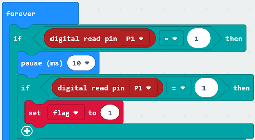
If the flag equals to 1, press the button once, run the flag block to 0, set count block plus 1;
So if count is greater than 9, then set count equal to 1, passive buzzer will ring a Middle C tone (262Hz);
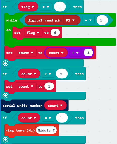
Next we can set 7 kinds of tones with different frequencies. When count is greater than 9, then set count to 1, the buzzer will loop play a Middle C tone (262Hz).
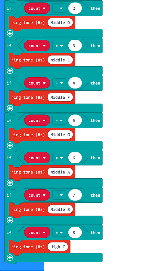
You can click the JavaScript on the coding block to check the tone frequency:
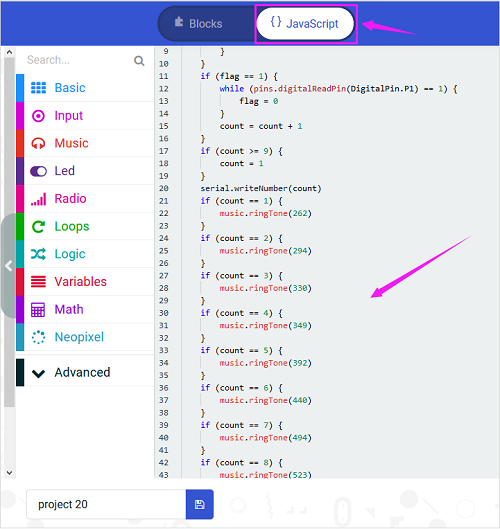
Run Code on Micro:bit
Connect the micro:bit to your computer with a micro USB cable. You can right-click the microbit HEX file to send to your micro:bit main board.

Done sending the code to micro:bit, open the serial monitor, it prints out the number from 1 to 8, and passive buzzer will make corresponding tone “Do Re Mi Fa Sol La Si Do”.
Each time you press the button, the number is increased by 1. After more than 8, it returns to 1.
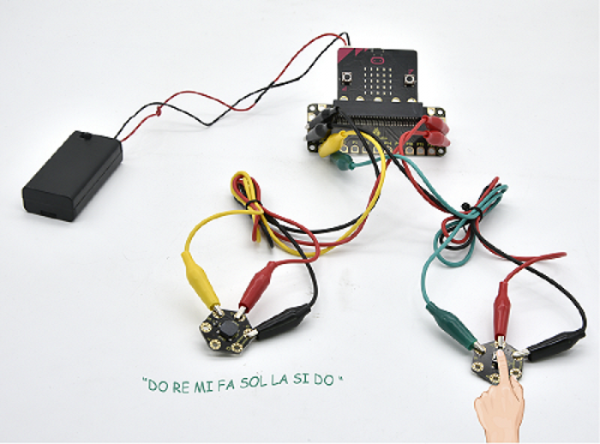
7.Download Projects Resources
Download all the microbit projects code:
https://drive.google.com/open?id=1JRmW98hizQpZzceVVLASSwxstDR7YZpW
More reference you can click the link below:
Keyestudio Official Website: www.keyestudio.com
Keyestudio Wiki website: wiki.keyestudio.com
BBC micro bit Pins:http://micro:bit.org/guide/hardware/pins/
BBC micro:bit website: http://micro:bit.org/
Micro bit MakeCode Block Editor: https://makecode.micro:bit.org/
Meet micro:bit starter programming: http://micro:bit.org/guide/
BBC micro:bit Features Guide: http://micro:bit.org/guide/features/
BBC micro:bit Safety Warnings: http://micro:bit.org/guide/features/
BBC micro:bit Quick Start Guide: http://micro:bit.org/guide/quick/
Our Tutorial
This tutorial is designed for everyone to play the MICRO:BIT. You will learn all the basic information about how to control the micro:bit, controller board, sensor modules and more to make interactive projects. Easy play and enjoy your time!
Is it great? Well, it's just the beginning of MICRO:BIT's journey. There are more and more awesome projects for you to explore. Furthermore, our KEYESTUDIO research and development team will continue to explore on this path, walking you through the basics up to complex projects. Hope that you can enjoy our works!
About keyestudio
Located in Shenzhen, the Silicon Valley of China, KEYES DIY ROBOT CO.,LTD is a thriving technology company dedicated to open-source hardware research & development, production and marketing. Keyestudio is a best-selling brand owned by KEYES Corporation, our product lines rang from Arduino boards, shields, sensor modules, Raspberry Pi, micro:bit extension boards and smart car to complete starter kits designed for customers of any level to learn Arduino knowledge.
All of our products comply with international quality standards and are greatly appreciated in a variety of different markets throughout the world. For more details of our products, you can check it from the links below.
- Official website: http://www.keyestudio.com/
- US Amazon storefront: http://www.amazon.com/shops/A26TCVWBQE4D9T
- CA Amazon storefront: http://www.amazon.ca/shops/A26TCVWBQE4D9T
- UK Amazon storefront: http://www.amazon.co.uk/shops/A39F7KX4U3W9JH
- DE Amazon storefront: http://www.amazon.de/shops/A39F7KX4U3W9JH
- FR Amazon storefront: http://www.amazon.de/shops/A39F7KX4U3W9JH
- ES Amazon storefront: http://www.amazon.de/shops/A39F7KX4U3W9JH
- IT Amazon storefront: http://www.amazon.de/shops/A39F7KX4U3W9JH
- US Amazon storefront: http://www.amazon.com/shops/APU90DTITU5DG
- CA Amazon storefront: http://www.amazon.ca/shops/APU90DTITU5DG
- JP Amazon storefront: http://www.amazon.jp/shops/AE9VWCCXQIC6J
Customer Service
As a continuous and fast growing technology company, we keep striving our best to offer you excellent products and quality service as to meet your expectation. We look forward to hearing from you and any of your critical comment or suggestion would be much valuable to us.
You can reach out to us by simply drop a line at Fennie@keyestudio.com
Thank you in advance.
