KS0486 Keyestudio PLUS Development Board (Black And Eco-friendly)
Description
Doing experiment for electronic products, we often program on the Arduino IDE development environment by arduino series microcontrollers.
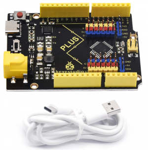
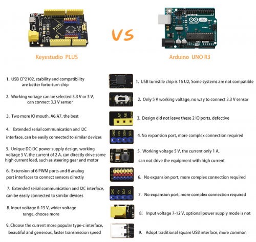
Keyestudio PLUS control board is fully compatible with Arduino IDE development environment. It contains all the functions of the Arduino UNO R3 board. Moreover, some improvements we made highly strengthen its function(as shown below). In order to wire efficiently, we equip with a 1m USB cable of type-c interface for you.
Specifications
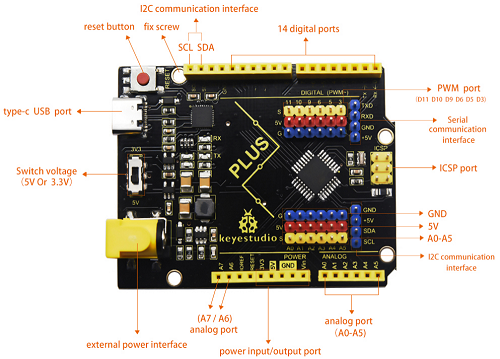
- USB to serial chip: CP2102
- Working voltage: 5V or 3.3V (DIP switch control)
- External power: DC 6-15V (recommend 9V)
- Digital I / O pins: 14 (D0-D13)
- PWM channel: 6 (D3 D5 D6 D9 D10 D11)
- Analog input channel (ADC): 8 (A0-A7)
- Each I / O Port of DC output capability : 20 mA
- Output capability of 3.3V port: 50 mA
- Flash Memory: 32 KB (of which 0.5 KB is used by the bootloader)
- SRAM: 2 KB (ATMEGA328P-AU)
- EEPROM: 1 KB (ATMEGA328P-AU)
- Clock speed: 16MHz
- On-board LED pin: D13
- Serial communication interface: D0 is RX, D1 is TX
- PWM interface (pulse width modulation): D3 D5 D6 D9 D10 D11
- External interrupt interface: D2 (interrupt 0) and D3 (interrupt 1)
- SPI communication interface: D10 is SS, D11 is MOSI, D12 is MISO, D13 is SCK
- IIC communication port: A4 is SDA, A5 is SCL
Instruction
Programming the control board, we need to download Arduino IDE.
You could download from the official website:
https://www.arduino.cc/en/Main/OldSoftwareReleases#1.5.x.
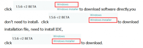
There are various versions of the IDE in the official link, here we download a Windows system, version 1.5.6.
Installing Arduino IDE
Double click arduino-1.5.6-r2-windows to start. Select “I Agree”to accept license agreement.
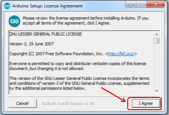
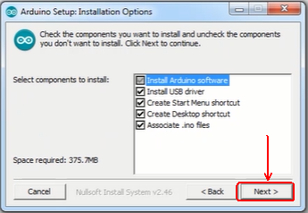
Select components to install and click “Next”.
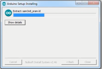
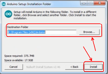
Click “Browse” and select another folder. Click “Install” to start the installation.
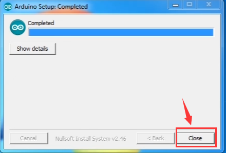
Finally, wait for a few minutes to finish.
4.2 Installing Driver
The corresponding driver is needed when using Arduino IDE. Its USB serial chip is CP2102. There are drivers of all edition systems in the link below.
https://www.silabs.com/products/development-tools/software/usb-to-uart-bridge-vcp-drivers
You can refer to the link below:
https://v.qq.com/x/page/s0367yegedj.html
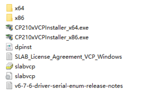
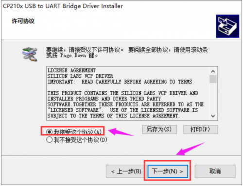
Next, we introduce the driver installation method of Windows systems. Open the driver file, as shown below.
Click ![]() click “next step”, as shown below:
click “next step”, as shown below:
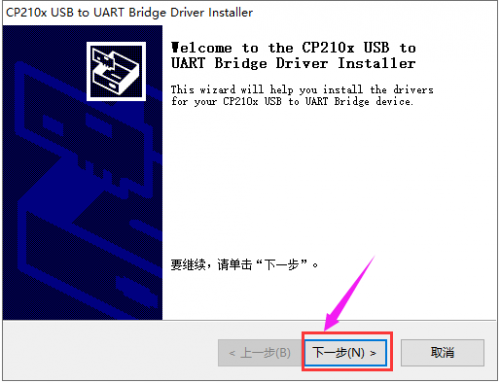
Click “next step”, as shown below:
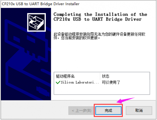
Installing successfully, click “complete” to end installation, as shown below.
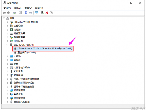
Right click computer ---> Properties ---> ---> Device Manager, then the corresponding COM port is shown. (as shown below)
Arduino IDE Setting
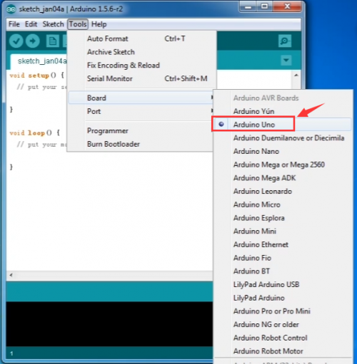
To avoid the errors when uploading the program to the board, you need to select the correct Arduino board that matches the board connected to your computer.
Then come back to the Arduino software, you should click Tools→Board, select the board. (as shown below)
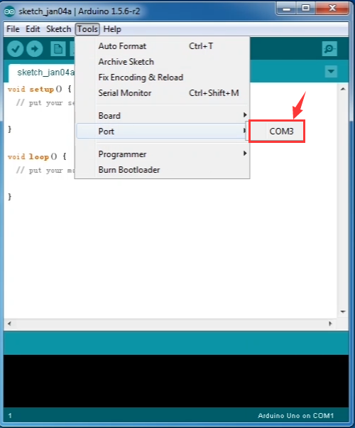
Then select the correct COM port (you can see the corresponding COM port after the driver is successfully installed)
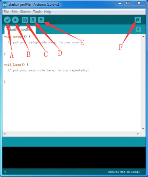
Before uploading the program to the board, let’s demonstrate the function of each symbol in the Arduino IDE toolbar.
A- Used to verify whether there is any compiling mistakes or not.
B- Used to upload the sketch to your Arduino board.
C- Used to create shortcut window of a new sketch.
D- Used to directly open an example sketch.
E- Used to save the sketch.
F- Used to send the serial data received from board to the serial monitor.
4.4 Hello World!
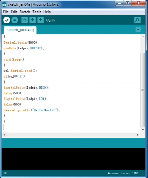
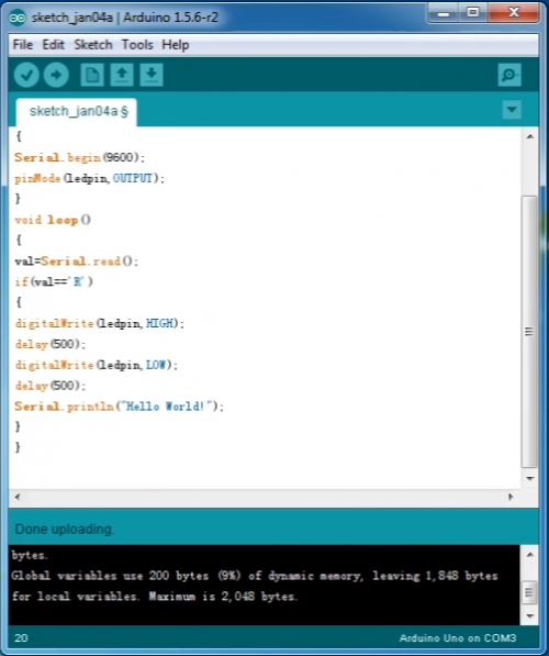
Copy the following code on the Arduino IDE
int val;
int ledpin=13;
void setup()
{
Serial.begin(9600);
pinMode(ledpin,OUTPUT);
}
void loop()
{
val=Serial.read();
if(val=='R')
{
digitalWrite(ledpin,HIGH);
delay(500);
digitalWrite(ledpin,LOW);
delay(500);
Serial.println("Hello World!");
}
}
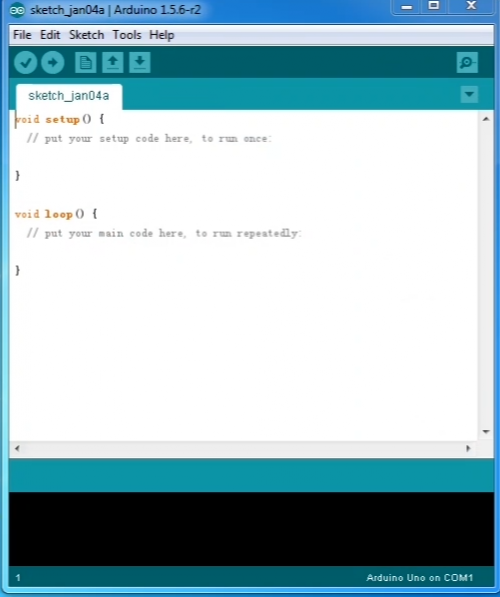
Set the board and COM port, the corresponding board and COM port are displayed in the lower right corner of the IDE.
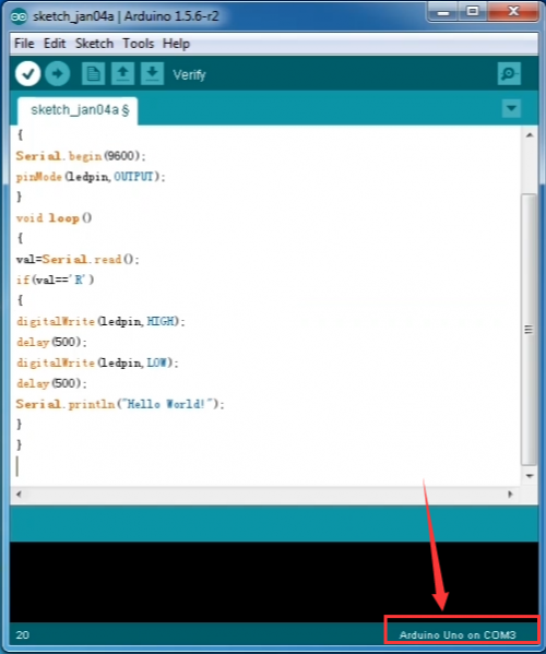
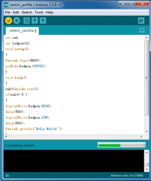
Click ![]() icon to start compiling the program.
icon to start compiling the program.
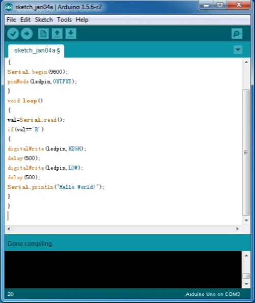
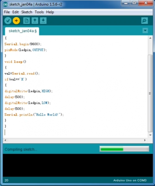
Click![]() icon to start upload the program, upload successfully.
icon to start upload the program, upload successfully.
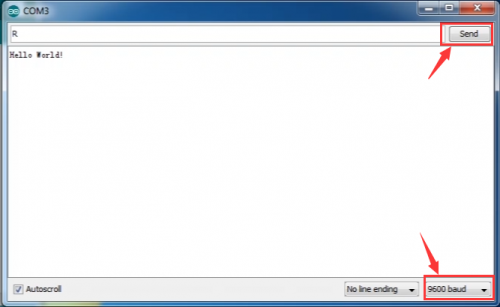
Click![]() to open serial monitor, set baud rate to 9600, enter “R” character, click “Send” (RX light will flash once when computer sends a “R” character to control board),then D13 indicator on the control board blinks once, "Hello World!" is shown on the serial monitor( control board sends "Hello World!" to the computer, TX light flashes once)
to open serial monitor, set baud rate to 9600, enter “R” character, click “Send” (RX light will flash once when computer sends a “R” character to control board),then D13 indicator on the control board blinks once, "Hello World!" is shown on the serial monitor( control board sends "Hello World!" to the computer, TX light flashes once)
