KS0488 Keyestudio 4DOF Robot Arm DIY Kit V2.0 for Arduino
Introduction
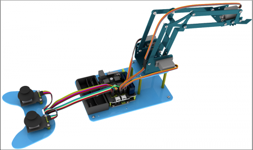
On the Internet, we often see DIY robotic arm complete various actions. Do you want to have one? I believe that you’ll make your own robotic arm by learning our projects.
This kit includes R3 single-chip microcomputer, 2 joystick modules and 4 servos so on. We’ll teach you how to install and debug the robotic arm.
There are 3 ways of controlling metal manipulator in this kit:
1.Use a wired home-made joystick controller (included in the kit)
2.Control via Bluetooth. (HM -10 Bluetooth module included, support Bluetooth 4.0, Android and IOS system). we also provide relevant test code and specially designed APP for robotic arm.
3.Use wireless PS2 joystick (not included in kit) module to control. We only provide relevant test codes.
Note: You must connect a DC 7-15V power to VIN port of shield when connecting servo to shield.
Features
- Detailed installation method.
- Detailed debugging methods, even you’re a beginner.
- 3 methods of controlling: wired joystick control, Bluetooth control, wireless PS2 joystick control.
- Relevant information provided
Specification
Keyestudio TB6612FNG Motor/Servo Drive Shield:
- VIN voltage: VIN = DC 7-15V
- VIN current: 5A
- Size: 73 * 53.34mm
- 2-channel 5V output: 5V / 3A
- TB6612FNG: VIN input DC 7-15V, average drive current 1.2A, peak current 3.2A.
- PS2 interface: compatible with Sony PS2 receiver, can be plugged directly into the shield.
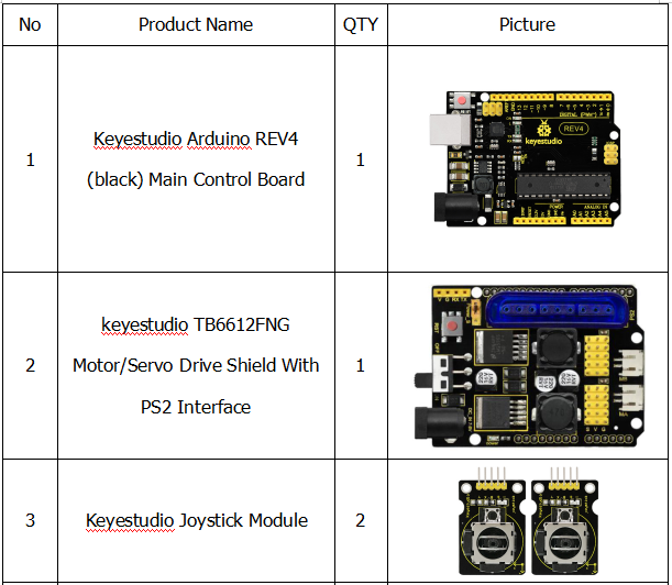
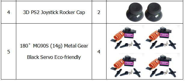
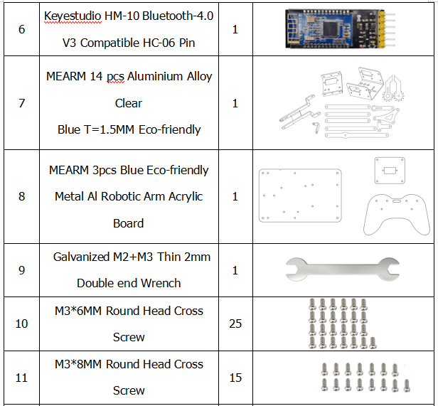
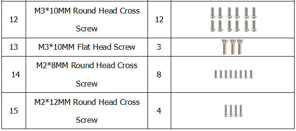
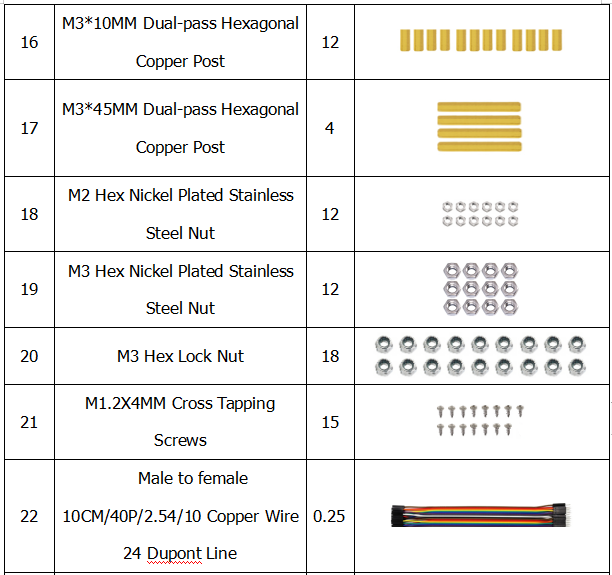
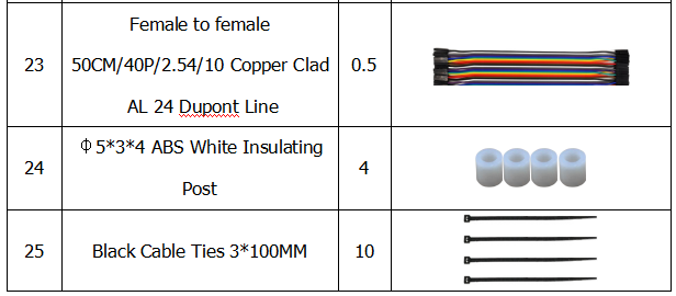
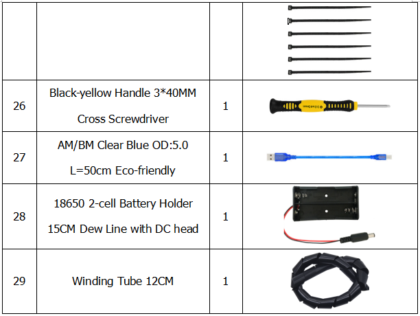
Component List
Robot Arm Projects
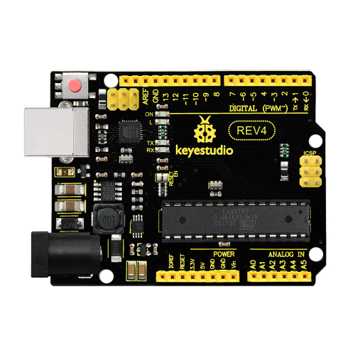
When it comes to using the UNO R3 as core of our robot, the UNO is the best board to get started with electronics and coding. If this is your first experience tinkering with the platform, the UNO is the most robust board you can start playing with. Well, let's at first have a look at this UNO R3 board.

|
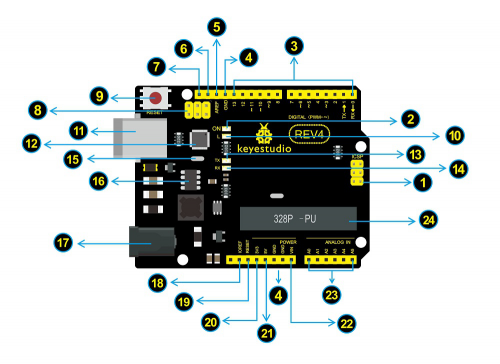
ICSP (In-Circuit Serial Programming) Header In most case, ICSP is the AVR,an Arduino micro-program header consisting of MOSI, MISO, SCK, RESET, VCC, and GND. It is often called the SPI (serial peripheral interface) and can be considered an "extension" of the output. In fact, slave the output devices under the SPI bus host. |

|
Power LED Indicator
Powering the Arduino, LED on means that your circuit board is correctly powered on. If LED is off, connection is wrong. |

|
Digital I/O
Arduino REV4 has 14 digital input/output pins (of which 6 can be used as PWM outputs). These pins can be configured as digital input pin to read the logic value (0 or 1). Or used as digital output pin to drive different modules like LED, relay, etc. The pin labeled “〜” can be used to generate PWM. |

|
GND ( Ground pin headers)
Used for circuit ground |

|
AREF
Reference voltage (0-5V) for analog inputs. Used with analogReference(). |

|
SDA
IIC communication pin |

|
SCL
IIC communication pin |

|
ICSP (In-Circuit Serial Programming) Header
In most case, ICSP is the AVR,an Arduino micro-program header consisting of MOSI, MISO, SCK, RESET, VCC, and GND. Connected to ATMEGA 16U2-MU. When connecting to PC, program the firmware to ATMEGA 16U2-MU. |

|
RESET Button
You can reset your Arduino board, for example, start the program from the initial status. You can use the RESET button. |

|
D13 LED
There is a built-in LED driven by digital pin 13. When the pin is HIGH value, the LED is on, when the pin is LOW, it's off. |

|
USB Connection
Arduino board can be powered via USB connector. |

|
ATMEGA 16U2-MU
USB to serial chip, can convert the USB signal into serial port signal. |

|
TX LED
Onboard you can find the label: TX (transmit) |

|
RX LED
Onboard you can find the label: RX(receive ) |

|
Crystal Oscillator
How does Arduino calculate time? by using a crystal oscillator. |

|
Voltage Regulator
Convert an external input DC7-12V voltage into DC 5V, then switch DC 5V to the processor and other components. Output DC 5V, the drive current is 2A. |

|
DC Power Jack
Arduino board can be supplied with an external power DC7-12V from the DC power jack. |

|
IOREF
Used to configure the operating voltage of microcontrollers. Use it less. |

|
RESET Header
Connect an external button to reset the board. The function is the same as reset button (labeled 9) |

|
Power Pin 3V3
A 3.3 volt supply generated by the on-board regulator. Maximum current draw is 50 mA. |

|
Power Pin 5V
Provides 5V output voltage |

|
Vin
You can supply an external power input DC7-12V through this pin to Arduino board. |

|
Analog Pins
Arduino REV4 board has 6 analog inputs, labeled A0 through A5. |

|
Microcontroller
Each Arduino board has its own microcontroller. You can regard it as the brain of your board. |
Installing Arduino IDE
When you get the REV3 development board, first you should install the software and driver of Arduino. You can see all the Arduino software versions from the link below:
https://www.arduino.cc/en/Main/OldSoftwareReleases#1.5.x
Or you can browse the ARDUINO website at this link, https://www.arduino.cc, pop up the following interface.

Then click the SOFTWARE on the browse bar, you will have two options ONLINE TOOLS and DOWNLOADS.

Click DOWNLOADS, it will appear the latest software version of ARDUINO 1.8.5 shown as below.
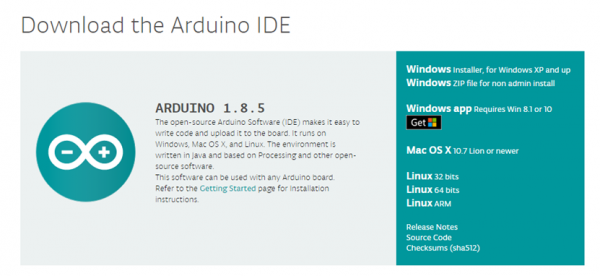
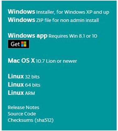
In this software page, on the right side you can see the version of development software for different operating systems. So ARDUINO has a rather powerful compatibility. You should download the software that is compatible with the operating system of your computer.
In our project, we will take WINDOWS system as an example here. There are also two options under Windows system, one is installed version, the other is non-installed version.
For simple installed version, first click Windows Installer, you will get the following page.

This way you just need to click JUST DOWNLOAD, then click the downloaded file to install it.
For non-installed version, first click Windows ZIP file, you will also get the pop-up interface as the above figure.
Click JUST DOWNLOAD, and when the ZIP file is downloaded well to your computer, you can directly unzip the file and then click the icon of ARDUINO program to start it.
When you get the REV4 development board, first you should install the Arduino software and driver.
We usually use the Windows software Arduino 1.5.6 version. You can download it from the link below:
https://www.arduino.cc/en/Main/OldSoftwareReleases#1.5.x
Or you can browse the ARDUINO website to download the latest version from this link, https://www.arduino.cc, pop up the following interface.

Then click the SOFTWARE on the browse bar, you will have two options ONLINE TOOLS and DOWNLOADS.

Click DOWNLOADS, it will appear the latest software version of ARDUINO 1.8.5 shown as below.

In this software page, on the right side you can see the version of development software for different operating systems. ARDUINO has a powerful compatibility. You should download the software that is compatible with the operating system of your computer.
We will take WINDOWS system as an example here. There are also two options under Windows system, one is installed version, the other is non-installed version.
For simple installed version, first click Windows Installer, you will get the following page.


This way you just need to click JUST DOWNLOAD, then click the downloaded file to install it.
For non-installed version, first click Windows ZIP file, you will also get the pop-up interface as the above figure.
Click JUST DOWNLOAD, and when the ZIP file is downloaded well to your computer, you can directly unzip the file and click the icon of ARDUINO software to start it.
Installing Arduino (Windows)
Install Arduino with the exe. Installation package downloaded well.
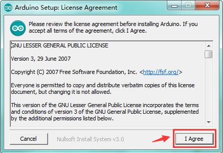
Click“I Agree”to see the following interface.
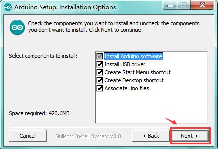
Click “Next”. Pop up the interface below.
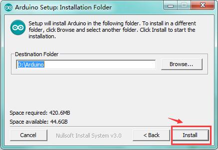
You can press Browse… to choose an installation path or directly type in the directory you want.
Then click “Install” to initiate installation.
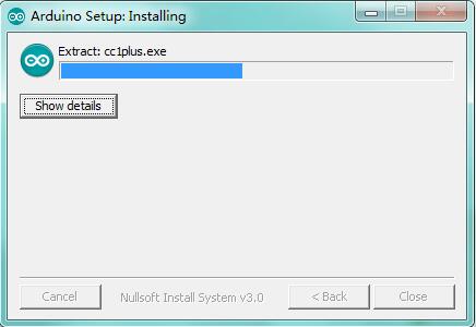
Wait for the installing process, if appear the interface of Window Security, just continue to click Install to finish the installation.
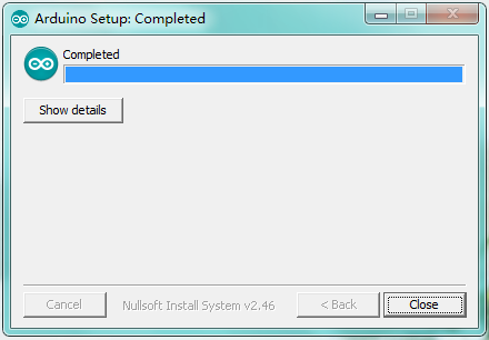
Installing Driver
Next, we will introduce the driver installation of REV4 development board. The driver installation may have slight differences in different computer systems. So in the following let’s move on to the driver installation in the WIN 7 system.
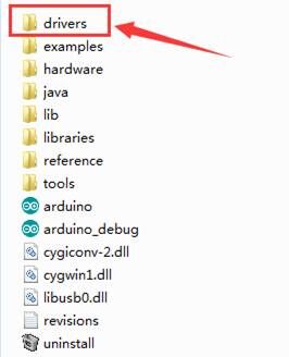
The Arduino folder contains both the Arduino program itself and the drivers that allow the Arduino to be connected to your computer by a USB cable. Before we launch the Arduino software, you are going to install the USB drivers.
Plug one end of your USB cable into the Arduino and the other into a USB socket on your computer.
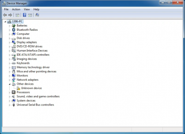
When you connect REV4 board to your computer at the first time, right click the icon of your “Computer” —>for “Properties”—> click the “Device manager”, under “Other Devices”, you should see an icon for “Unknown device” with a little yellow warning triangle next to it. This is your Arduino.
Then right-click on the device and select the top menu option (Update Driver Software...) shown as the figure below..
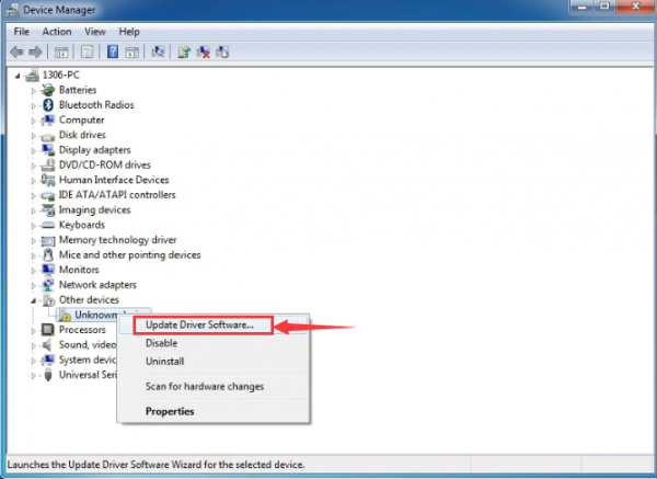
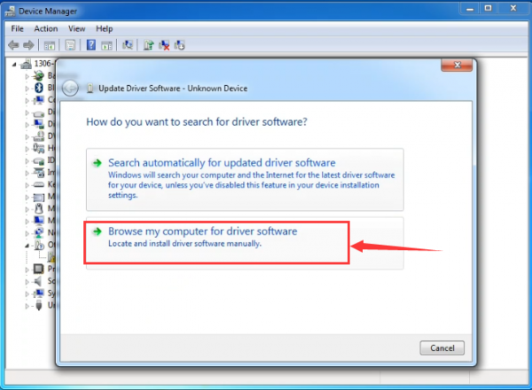
It will then be prompted to either “Search Automatically for updated driversoftware” or “Browse my computer for driver software”. Shown as below. In this page, select “Browse my computer for driver software”.
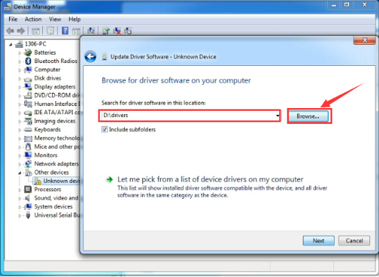
After that, select the option to browseand navigate to the “drivers” folder of Arduino installation.
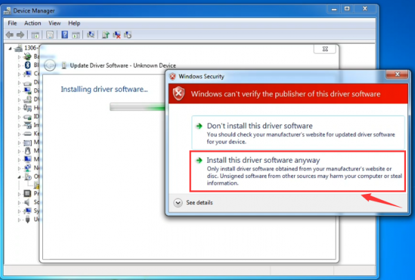
Click “Next” and you may get a security warning, if so, allow the software to be installed. Shown as below.
Once the software has been installed, you will get a confirmation message. Installation completed, click “Close”.
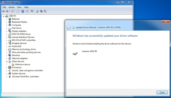
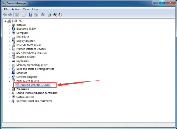
Up to now, the driver is installed well. Then you can right click “Computer” —>“Properties”—>“Device manager”, you should see the device as the figure shown below.
Introduction for Arduino IDE Toolbar
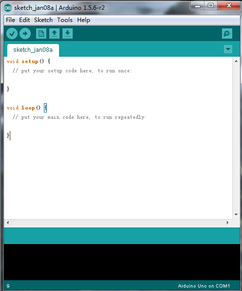
Double-click the icon of Arduino software downloaded well, you will get the interface shown below.
(Note: if the Arduino software loads in the wrong language, you can change it in the preferences dialog. See the environment page for details.)
The functions of each button on the Toolbar are listed below:
![]()
Project 2: Joint Rotation and Pin Control
Joint Rotation and Servo Angle Settings
| Name | 0° | 180° |
|---|---|---|
| Servo 1(baseplate) | Rotate toward the rightmost | Rotate toward the leftmost |
| Servo 2(right side) | Rocker arm connected to Servo 2 stretches out | draw back |
| Servo 3(left side) | Rocker arm connected to Servo 3 draws back | stretches out |
| Servo 4(clamp claw) | closed | opened |
Pin Control
| Name | IO Pin |
|---|---|
| Servo 1 (baseplate) | A1 |
| Servo 2 (left side) | A0 |
| Servo 3(right side) | 8 |
| Servo 4(clamp claw) | 9 |
| Right Joystick X | A2 |
| Right Joystick Y | A5 |
| Right Joystick Z (key) | 7 |
| Left Joystick X | A3 |
| Left Joystick Y | A4 |
| Left Joystick Z | 6 |
| D1/DAT of PS2 | 12 |
| D0/CMD of PS2 | 10 |
| CE/SEL of PS2 | 11 |
| CLK of PS2 | 13 |
Project 3: JoyStick Controlling Robot Arm
How to adjust the Servo Angel
Description
Here we control the angle of a single servo with servo library file.
The test result is same. Before using it, we need to put the servo folder in the folder where the Arduino IDE is installed, and then open the Arduino IDE, the library file will take effect.
Test Code
#include <Servo.h>
Servo myservo;  // create servo object to control a servo

void setup()
{
  Serial.begin(9600);
  delay(1000);
}

void loop()
{
  myservo.attach(A0);  // modify each pin to adjust
  myservo.write(0);  // angle value
  delay(1000);
}
Test Result
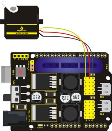
Stack the driver shields on the UNO R3 board, upload the code, and wire according to connection diagram. After powering on, press the reset button, the servo will automatically rotate to 0°.
Rotating Automatically
Description
In the previous lesson, we set the angle for a single servo. In fact, we only need to continuously change the angles of the 4 servos to enable the 4 DOF robotic arm to perform different movements.
Test Code
#include <Servo.h>
Servo myservo1;  // create servo object to control a servo
Servo myservo2;
Servo myservo3;
Servo myservo4;
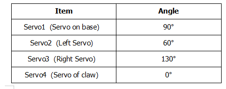
int pos1=90, pos2=60, pos3=130, pos4=0;

void setup()
{
  myservo1.attach(A1);  // attaches the servo on pin 9 to the servo object
  myservo2.attach(A0);
  myservo3.attach(8);
  myservo4.attach(9);

  myservo1.write(pos1);
  delay(1000);
  myservo2.write(pos2);
  myservo3.write(pos3);
  myservo4.write(pos4);
  delay(1500);
}

void loop()
{
  // turn right
  for(pos1;pos1>0;pos1--)
  {
    myservo1.write(pos1);
    delay(5);      // delay 5ms(used to adjust the servo speed)
  }
  delay(1000);

  // open the claw
 for(pos4;pos4<100;pos4++)
 {
   myservo4.write(pos4);
 }
  delay(1000);

  // right servo rotates to 100 degrees
  for(pos2;pos2<100;pos2++)
  {
    myservo2.write(pos2);
    delay(5);
  }
  // left servo rotates to 5 degrees
  for(pos3;pos3<180;pos3++)
  {
    myservo3.write(pos3);
    delay(5);
  }
  delay(1500);

  // close the claw
  for(pos4;pos4>0;pos4--)
  {
    myservo4.write(pos4);
  }
  delay(1000);

  // left servo rotates to100 degrees, rocker arm lifts.
  for(pos3;pos3>120;pos3--)
  {
    myservo3.write(pos3);
    delay(5);
  }
  delay(1000);

  // turn to left
  for(pos1;pos1<180;pos1++)
  {
    myservo1.write(pos1);
    delay(5);
  }
  delay(1000);

  // Lower the arm
  for(pos3;pos3<180;pos3++)
  {
    myservo3.write(pos3);
    delay(5);
  }
  delay(1000);

  // open the claw
  for(pos4;pos4<100;pos4++)
  {
    myservo4.write(pos4);
  }
  delay(1000);

  // lift up the arm
  for(pos3;pos3>120;pos3--)
  {
    myservo3.write(pos3);
    delay(5);
  }
  delay(1000);

  // close the claw
  for(pos4;pos4>0;pos4--)
  {
    myservo4.write(pos4);
  }
  delay(1000);
}
Test Result
Stack the driver shield on the REV4 board, upload the code, and wire according to connection diagram. After powering on, press the reset button, the DOF robot arm realizes a cyclical movement: turn to the right, the paw releases, arm is stretched out, lower down and the paw closes, then the robot arm is retracted and raised; turn to the left, the robot arm is stretched out, lower down, claw releases, robotic arm is retracted and raised, claw closes, and then return to the right to continue to repeat the motion.
Read the JoyStick Value
Description
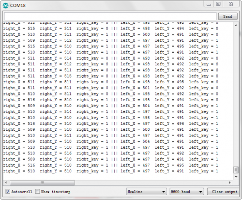
The sensor’s pin X, Y are for analog sensor, so directly read the measured analog value. Pin Z is a digital button, first should set the pin to Input status and then read the measured value 1 (pressed down) or 0 (not press). Check out the value printed on the serial monitor.
Test Code
const int right_X = A2; // define the right X pin to A2
const int right_Y = A5; // define the right Y pin to A5
const int right_key = 7; //define the right key pin to 7(that is the value Z)

const int left_X = A3; //define the left X pin to A3
const int left_Y = A4;  // define the left Y pin to A4
const int left_key = 6; //define the left key pin to 8(that is the value Z)

void setup()
{
  pinMode(right_key, INPUT);   // set the right/left key to INPUT
  pinMode(left_key, INPUT);
  Serial.begin(9600); //  set the baud rate to 9600
}

void loop()
{
  int x1,y1,z1;  // define the variable, used to save the joystick value it reads
  int x2,y2,z2;

  x1 = analogRead(right_X); // read the value of right X
  y1 = analogRead(right_Y);  // read the value of right Y
  z1 = digitalRead(right_key);  //// read the value of right Z

  x2 = analogRead(left_X);  // read the value of left X
  y2 = analogRead(left_Y);  // read the value of left Y
  z2 = digitalRead(left_key);  // read the value of left Z

  //Serial.println("**********right**********");
  Serial.print("right_X = "); // on the serial monitor, print out right_X =
  Serial.print(x1 ,DEC); // print out the value of right X and line wrap
  Serial.print("  ");
  Serial.print("right_Y = ");
  Serial.print(y1 ,DEC);
  Serial.print("  ");
  Serial.print("right_key = ");
  Serial.print(z1 ,DEC);
  Serial.print(" ||| ");
  //Serial.println("*********left***********");
  Serial.print("left_X = ");
  Serial.print(x2 ,DEC);
  Serial.print("  ");
  Serial.print("left_Y = ");
  Serial.print(y2 ,DEC);
  Serial.print("  ");
  Serial.print("left_key = ");
  Serial.println(z2 ,DEC);

  delay(200);
}
Test Result:
Hook it up and upload well the code. Connect the REV4 control board to computer using a USB cable, then open the serial monitor and set the baud rate to 9600, you will see the analog value of the right Joystick pin X,Y, digital signal 1 or 0 of pin Z. As shown below:
Project 4: Assembly Guide
Adjusting angle of Servo
Step1: Begin with the Base plate Assembly
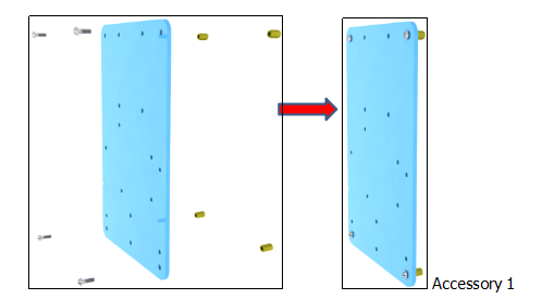
(1)Firstly, you should prepare the components as follows:
- 4pcs M3*10MM dual-pass hex copper posts
- 4pcs M3*6MM round head cross screws
- An Acrylic board
Install them together to form accessory 1. (Note: Notch of Acrylic board faces left)
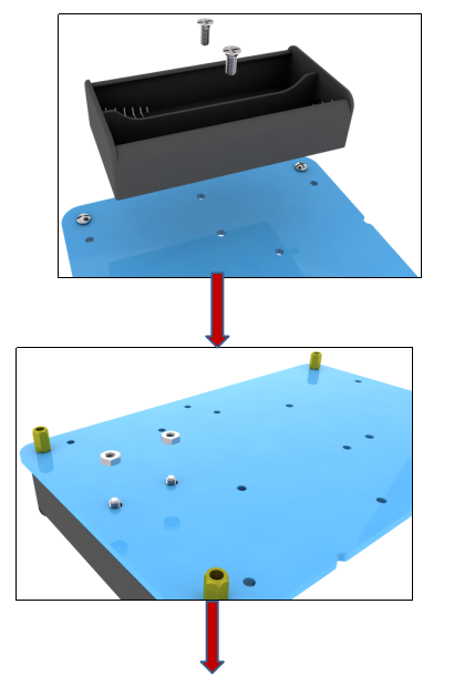
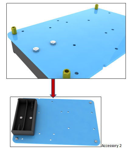
(2)Components needed as below:
- 2pcs M3*10MM flat head cross screws,
- 2pcs M3 hex nickel plated stainless steel nuts
- Accessory 1
Install them together to form accessory 2.
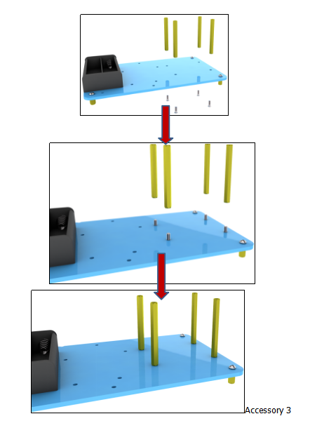
(3)Components needed as below:
- 4pcs M3 * 6MM round head cross screws
- 4pcs M3 * 45MM dual-pass hex copper posts
- Accessory 2
Fix them together to form accessory 3.
(4)Components needed as below:
- 2pcs M2 * 8MM round head cross screws
- 2pcs M2 hex nickel-plated stainless steel nut
- 1 pcs 180°metal gear servo
- 1 Acrylic board
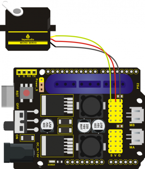
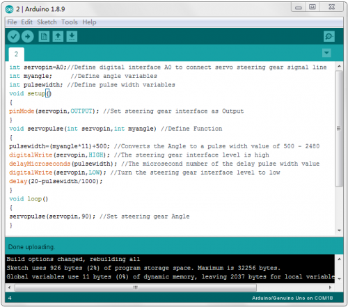
A. Before installing, set the servo angle to 90 °, stack the keyestudio TB6612FNG motor drive shield on the Keyestudio Arduino REV4 (black) main control board,and install the servo on the motor drive shield.
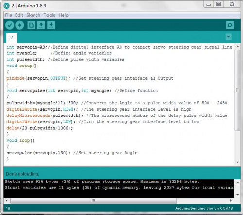
B.Use Arduino software to upload test code on the Keyestudio TB6612FNG motor drive shield to turn the servo to 90 °. When setting the servo angle, connect the servo to the A0 end of the shield(there is a silk screen on the back of the shield), then stack the shield on the REV4 board, upload the corresponding code on the REV4 board. And power on, press the reset button, the servo can be removed when turned to 80 °
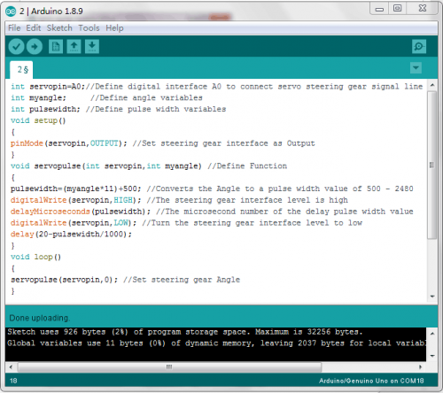
Code for 90° Servo:br>
int servopin=A0;//Define digital interface A0 to connect servo steering gear signal line
int myangle;     //Define angle variables
int pulsewidth; //Define pulse width variables
void setup()
{
pinMode(servopin,OUTPUT); //Set steering gear interface as Output
}
void servopulse(int servopin,int myangle) //Define Function
{
pulsewidth=(myangle*11)+500; //Converts the Angle to a pulse width value of 500 - 2480
digitalWrite(servopin,HIGH); //The steering gear interface level is high
delayMicroseconds(pulsewidth); //The microsecond number of the delay pulse width value
digitalWrite(servopin,LOW); //Turn the steering gear interface level to low
delay(20-pulsewidth/1000);
}
void loop()
{
servopulse(servopin,90); //Set steering gear Angle
}

//0 Degree Code:
//    servopulse(servopin,0);
//90 Degree Code:
//    servopulse(servopin,90);
//180 Degree Code:
//    servopulse(servopin,180);
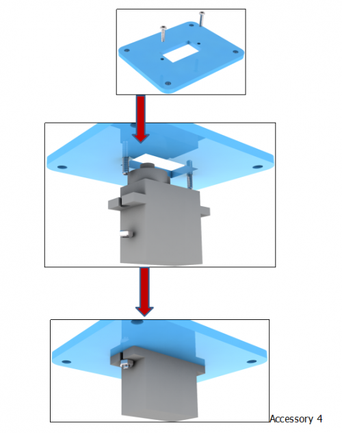
C. Remove servo, install 2pcs M2*8MM round head screws, 2pcs M2 hex nickel-plated stainless steel nut, 1pcs 180°metal gear servo and 1 acrylic board together to form accessory 4.
(5)Assemble accessory 3 and accessory 4 into accessory 5 with 4pcs M3 * 6MM round head cross screws.
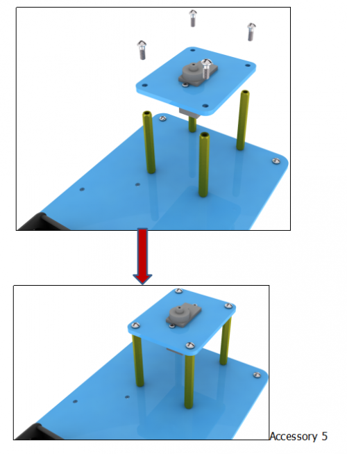
Step2: Assemble Arm Middle Parts
Components needed as below:
- 4pcs M1.2 * 4MM cross self-tapping screws
- black servo cross (included with servo)
- 1pcs M2 * 5 screw (included with servo) and corresponding metal board
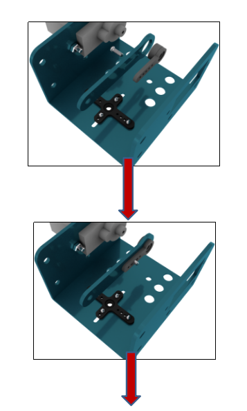
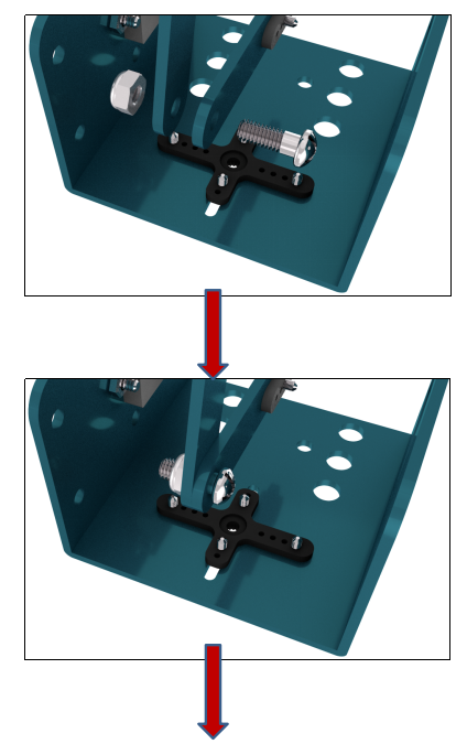
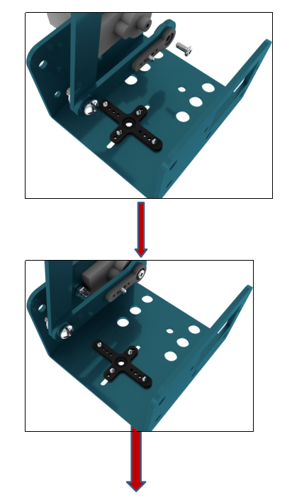
Fix the servo cross on the corresponding metal board with 4pcs M1.2 * 4MM cross self-tapping screws to generate accessory 6.
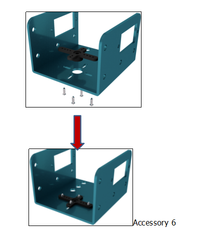
Components needed as below:
- 2 pcs M2 * 8MM round head cross screws
- 2 pcs M2 hex nickel-plated stainless steel nuts
- 180°metal gear Servo and accessory 6
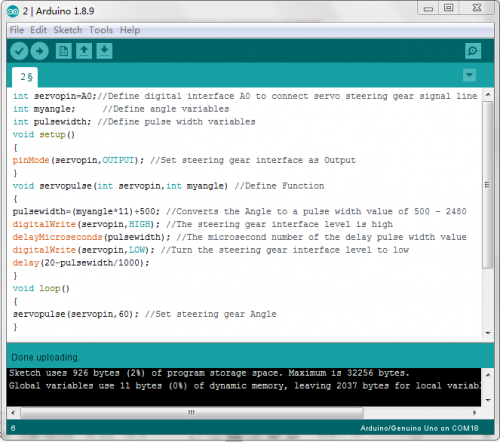
a.Need to set the Servo angle to 60 ° , the setting method is same as step 4. You only need to change the “servopulse (servopin, 90)” into “servopulse (servopin, 60)” in the test code.
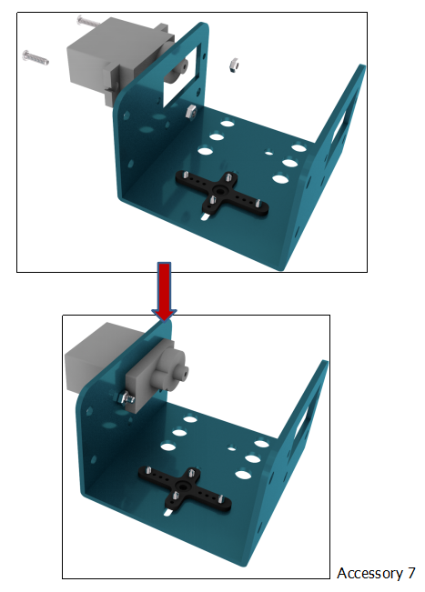
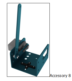
b.Remove Servo, install 2 pcs M2 * 8MM round head screws, 2 pcs M2 hex nickel-plated stainless steel nuts, 1 pcs 180°metal gear Servo and accessory 6 to form accessory 7.
(3)Components needed as below:
- 1pcs M1.2 * 4MM cross self-tapping screw
- 1pcs M3 * 8MM round head cross screw
- 1pcs M3 hexagonal self-locking nut
- 1pcs shortest corresponding metal slat
- 1pcs longer corresponding metal slat
- 1 pcs M2 * 5 screws (included with servo)
- a black Servo unilateral stand (included with servo )
- Accessory 7
Install the above components together into accessory 8.
Components needed as below:
- 1pcs M3 * 8MM round head cross screw.
- 1pcs M3 hexagonal self-locking nut
- 1pcs "L" corresponding metal
- 1pcs "Y" corresponding metal
- 1pcs M1.2 * 4MM cross self-tapping screw
- One black Servo unilateral bracket (included with servo)
Assemble them together to form accessory 9
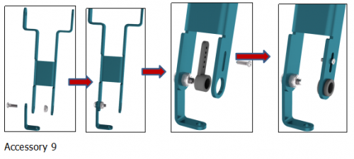
(4)Components needed as below:
- 1pcs M3 * 8MM round head cross screw
- 1pcs M3 hexagon lock self-locking nut
- 2 pcs M2 * 8MM round head cross screws
- 2 pcs M2 hexagon nickel-plated stainless steel nuts
- 1pcs 180 degree metal gear Servo
- 1 pcs M2 * 5 screws (included with Servo)
- Accessory 8 and accessory 9
A. Need to set the Servo angle to 130 ° before installing. When setting the Servo angle, the setting method is same as step 5 above, change servopulse (servopin, 90) code into servopulse (servopin, 130) in the test code.
B. Remove Servo, install accessory 8 and accessory 9 with 1pcs M3 * 8MM round head cross screw, 1pcs M3 hex lock self-locking nut, 2 pcs M2 * 8MM round head cross screws, 2 pcs M2 hex nickel-plated stainless steel nut, 1pcs 180 degree Servo, 1 pcs M2 * 5 screws (included with Servo) to form accessory 10
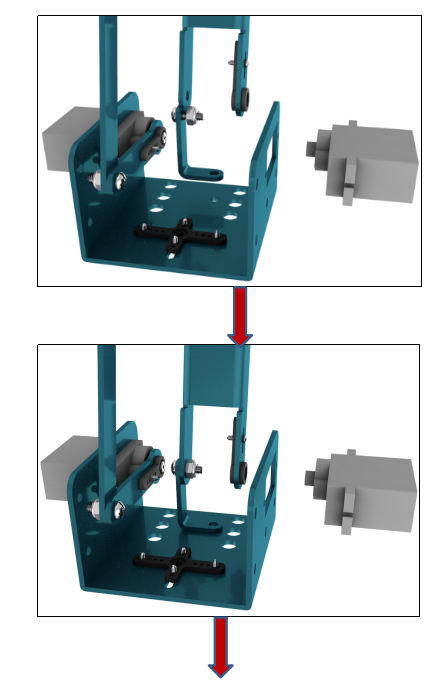
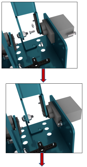
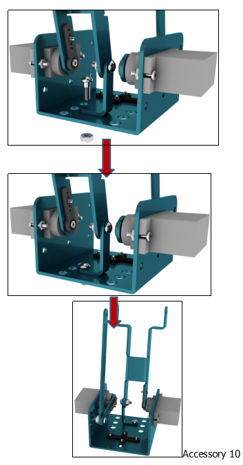
(5)Prepare the components as below:
- 1pcs M3 * 8MM round head cross screw
- 1pcs M3 hexagonal lock self-locking nut
- 1pcs longer corresponding metal slats and accessory 10
Install them together to form accessory 11.
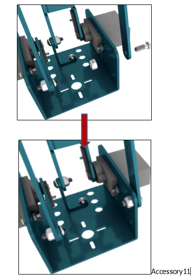
- 2pcs M3 * 8MM round head cross screws
- 2pcs M3 hexagonal lock self-locking nuts
- 1pcs long metal slat with holes in the middle
- Accessory 11
Mount them to form accessory 12.
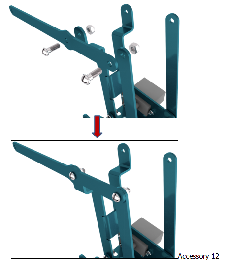
Prepare the components as below:
- 2pcs M3 * 8MM round head cross screws
- 1pcs M3 * 10MM round head cross screw
- 3pcs M3 hexagonal lock self-locking nuts
- 1pcs triangle corresponding metal plate
- 1pcs longer corresponding metal plate
- 1pcs the longest corresponding metal slat and accessory 12
Install them together to form accessory 13.
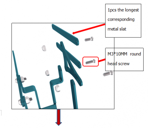
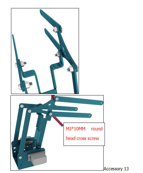
Then we start to install claw servo part.
Step3: Assemble the Claw Servo Plate
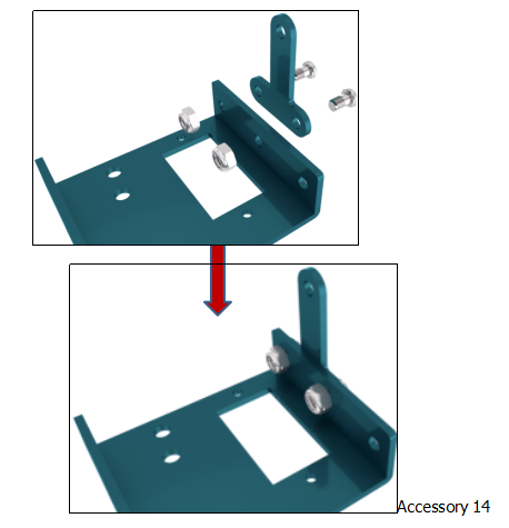
Prepare components as below:
- 2pcs M3 * 6MM round head cross screws
- 2pcs M3 hexagonal lock nuts
- 1pcs “T” corresponding metal plate
- 1pcs corresponding metal plate
Install them together to form accessory 14.
- 3pcs M3 * 8MM round head cross screws
- 3pcs M3 hex lock nuts
- Accessory 13 and Accessory 14
Install them together to form accessory 15
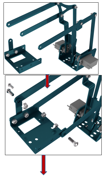
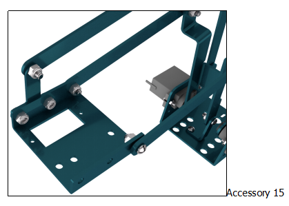
Prepare components as below:
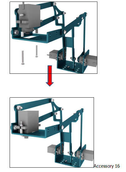
- 2 pcs M2 * 12MM round head cross screws
- 2 pcs M2 hexagon nickel-plated stainless steel nuts
- 2pcs straight pipe φ5 * 3 * 4 white insulated posts
- 1pcs 180 degree Servo and accessory 15
A.Need to set the Servo angle to 0 ° before installing. When setting the Servo angle, the setting method is the same as the step 5 above, only change servopulse (servopin, 90) code is changed to servopulse (servopin, 0) in the test code.
B.Remove Servo first. C.Components needed as below:
- 2 pcs M2 * 12MM round head cross screws
- 2 pcs M2 hex nickel-plated stainless steel nuts
- 2pcs straight pipe φ5 * 3 * 4 white insulated posts
- 1pcs 180 degree metal gear Servo and accessory 15
Fix the above components together to form accessory 16
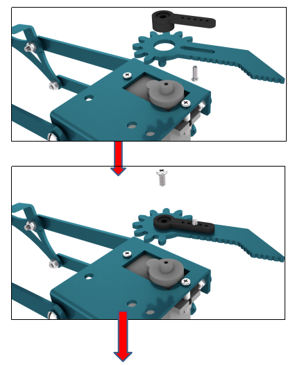
- 1pcs M1.2 * 4MM cross self-tapping screw
- a black Servo unilateral bracket (included with servo)
- 1pcs corresponding metal block with gear
- 1 pcs M2 * 5 screw (servo comes with) and accessory 16
Install them together to form accessory 17
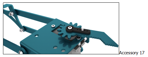
- 1pcs M3 * 10MM round head cross screw
- 2pcs M3 hexagonal lock self-locking nuts
- 1pcs corresponding block with gear
- Accessory 17
Install them together into accessory 18.
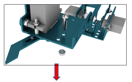
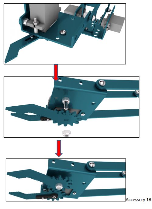
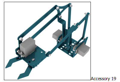
Let’s fix the claw servo part and middle part together to form accessory 19.
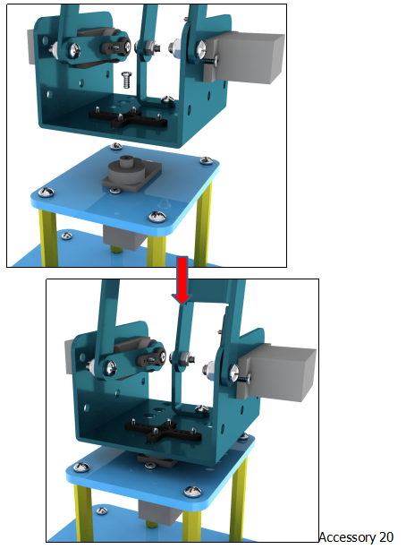
Install accessory 5 and accessory 19 together with 1 pcs M2 * 5 screws (supplied by Servo) to get accessory 20.
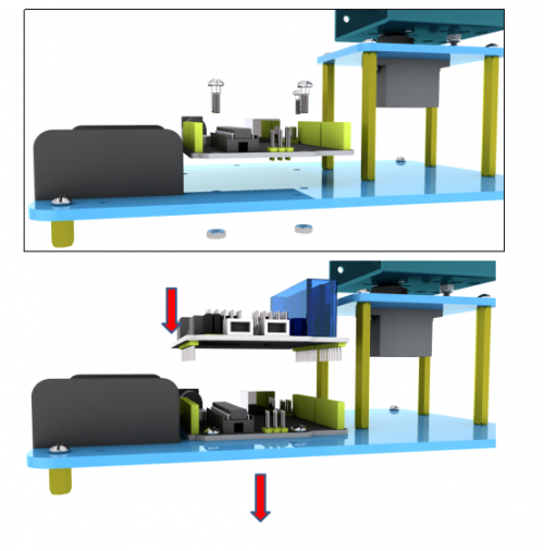
Fix the Keyestudio Arduino REV4(black) main control board on the accessory 20 with 3pcs M3 * 6MM round head cross screws , and stack the keyestudio TB6612FNG motor drive shield on the main control board to form accessory 21.
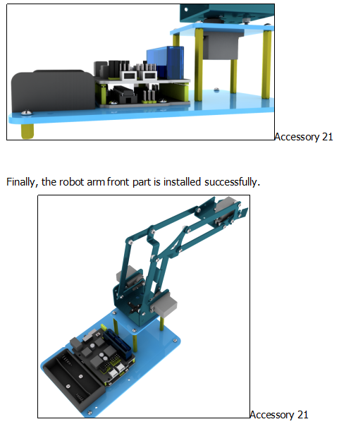
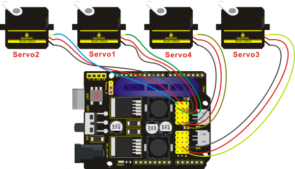
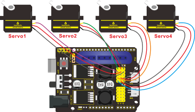
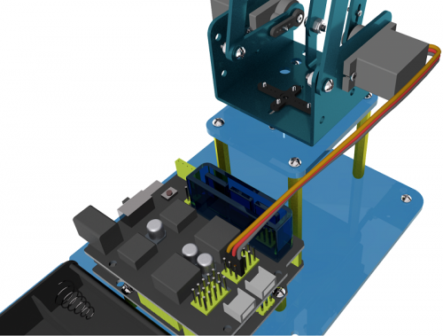
Then we connect the Servo to the corresponding interface of the Servo shield of the accessory 22, wiring method is as shown below, and the accessory 22 is generated.
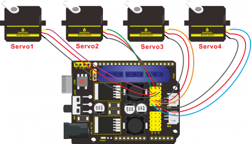
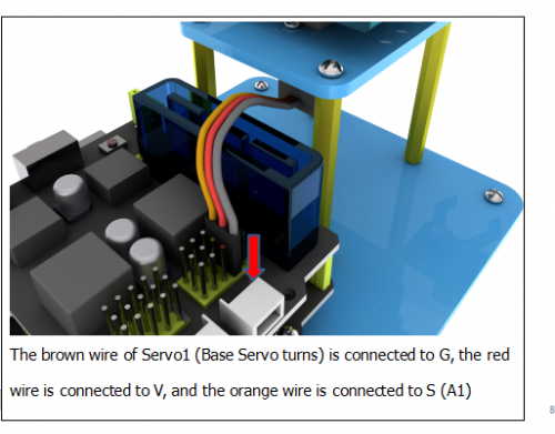
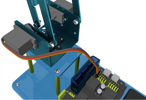
The brown wire of Servo 2(left side) is connected to G, the red wire to V,the orange wire to S(A0).
The brown wire of Servo3(right side)is connected to G,red wire to V,the orange wire to S(8)
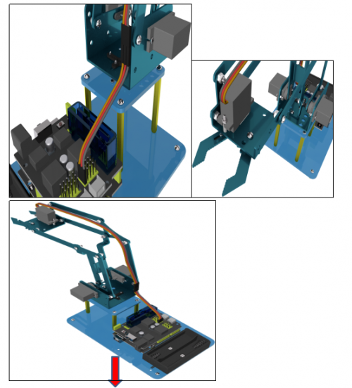
Connect the brown wire of servo 4 (claw servo) to G, the red wire to V, and the orange wire to S (9) with 3 male-to-female DuPont wires
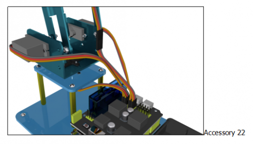
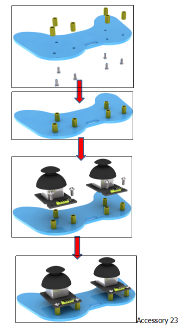
8.We start to install the robotic arm control part. Prepare the following components as below:
- 6pcs M3 * 10MM double-pass hexagonal copper posts,
- 10pcs M3 * 6MM round head cross screws
- 2pcs joystick modules
- A blue acrylic board
Fix the above components to generate accessory 23.
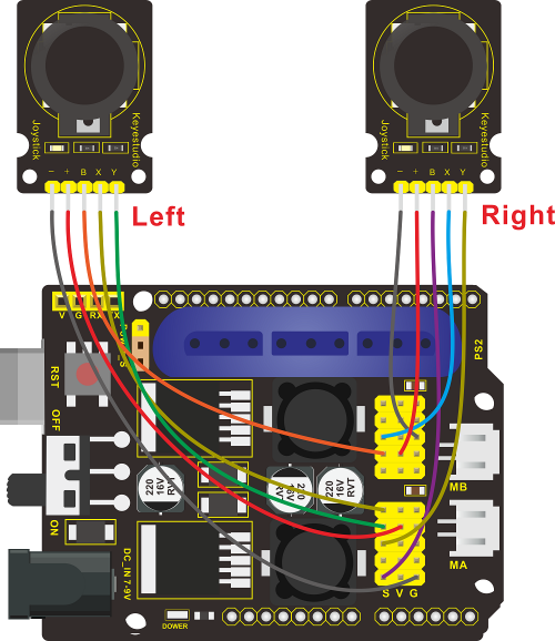
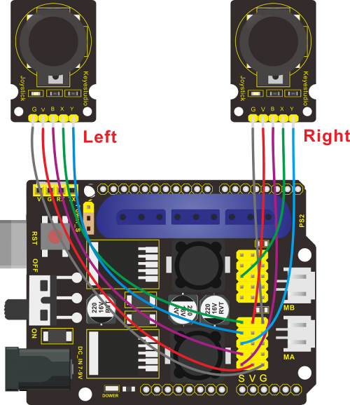
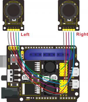
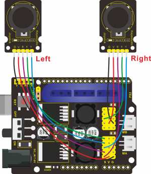
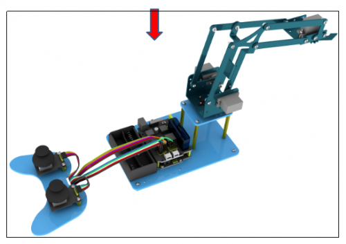
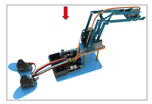
Connect accessory 22 and 23 together with a female-to-female DuPont line, according to the following connection diagram. Then we completes 4 DOF robotic arm, and upload the corresponding code to achieve the corresponding function.
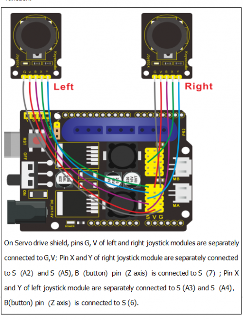
Note: Refer to the following figure:
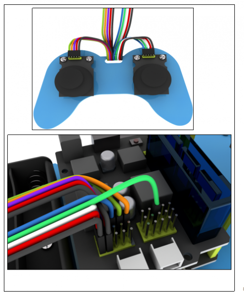
On Servo shield, the pin G,V of left and right joystick modules are separately connected to G, V;Pin X and Y of right joystick module are separately connected to S(A2) and S(A5),(button)pin (Z axis) is connected to S(7); Pin X and Y of left joystick module are separately connected to S(A3) and S(A4), B (button) pin (Z axis) is connected to S(6).
Project 5: Dual-JoyStick Controlling
Description:
In the previous section, we have introduced how to use 4 Servos to control the robot arm. Next, combine those two experiments. Use two Joystick modules to control 4DOF robot arm realize different motions.
At first, set the boot posture. The Joystick control is shown as below table.
| Right Joystick | Servo | Left Joystick | Servo |
|---|---|---|---|
| X1<50 | Servo 1 gradually reduces to 0° (push the right joystick to the right, the servo that controls the arm rotation turns right, and stops at 0° ) | X2<50 | Servo 4 gradually reduces to 0° (push the left joystick to the right, the claw is closes) |
| X1>1000 | Servo 1 gradually increases to 180° (push the right joystick to the left, the servo that controls the arm rotation turns left, and stops at 180° ) | X2>1000 | Servo 4 gradually increases to 110° (push the left joystick to the left, the claw opens) |
| Y1>1000 | Servo 3 gradually increases to 180° ( that is, right joystick stretches out, the upper arm stretches out) | Y2>1000 | Servo2 gradually reduces to 35° ( that is, left joystick stretches out and the lower arm lifts up) |
| Y1<50 | Servo 2 gradually reduces to 0° ( that is,the right joystick draws back, the upper arm draws back) | Y2<50 | Servo 2 gradually increases to 180° ( that is, left joystick draws back ,the lower arm decrease) |
Test Code
#include <Servo.h>  //add Servo library file
Servo myservo1;  // create servo object to control a servo
Servo myservo2;
Servo myservo3;
Servo myservo4;

int pos1=90, pos2=60, pos3=130, pos4=0;  // define the variable of 4 servo angle,and assign the initial value (that is the boot posture angle value)


const int right_X = A2; // define the right X pin to A2
const int right_Y = A5; //define the right Y pin to A5
const int right_key = 7; // define the right key to 7(the value of Z axis)
const int left_X = A3; // define the left X pin to A3
const int left_Y = A4;  // define the left Y pin to A4
const int left_key = 6; // define the left key to 6(the value of Z axis)

int x1,y1,z1;  //define a variable to store the read Joystick value
int x2,y2,z2;

void setup()
{
  //Serial.begin(9600); //  set the baud rate to 9600

  //start up posture
  myservo1.write(pos1);
  delay(1000);
  myservo2.write(pos2);
  myservo3.write(pos3);
  myservo4.write(pos4);
  delay(1500);

  pinMode(right_key, INPUT);   // set the right/left key to INPUT
  pinMode(left_key, INPUT);
  //Serial.begin(9600); //  set baud rate to 9600
}

void loop()
{
  myservo1.attach(A1);  //set the control pin of Servo1 to A1
  myservo2.attach(A0);  //set the control pin of Servo2 to A0
  myservo3.attach(8);   //set the control pin of Servo3 to D8
  myservo4.attach(9);   //set the control pin of Servo4 to D9

  x1 = analogRead(right_X); // read the value of right X axis

  y1 = analogRead(right_Y);  // read the value of right Y axis
  z1 = digitalRead(right_key);  ////read the value of right Z axis

  x2 = analogRead(left_X);  //read the value of left X axis
  y2 = analogRead(left_Y);  //read the value of left Y axis
  z2 = digitalRead(left_key);  //read the value of left Z axis
  //delay(5);  //lower the speed overall
    //Serial.println("**********right**********");
  //Serial.print("right_X = "); // on the serial monitor, print out right_X =
  //Serial.print(x1 ,DEC); // print out the value of right X and line wrap
  //Serial.print("  ");
  //Serial.print("right_Y = ");
  //Serial.print(y1 ,DEC);
  //Serial.print("  ");
  //Serial.print("right_key = ");
  //Serial.print(z1 ,DEC);
  //Serial.print(" ||| ");
  //Serial.println("*********left***********");
  //Serial.print("left_X = ");
  //Serial.print(x2 ,DEC);
  //Serial.print("  ");
  //Serial.print("left_Y = ");
  //Serial.print(y2 ,DEC);
  //Serial.print("  ");
  //Serial.print("left_key = ");
  //Serial.println(z2 ,DEC);

  //clamp claw
  zhuazi();
  //rotate
  zhuandong();
  //Right Servo
  right_ser();
  //Left Servo
  left_ser();
}

//Claw
void zhuazi()
{
    //Claw
  if(x2<50) //if push the left joystick to the right
  {
      pos4=pos4-1;  //current angle of servo 4 subtracts 1(change the value you subtract, thus change the closed speed of claw)
      //Serial.println(pos4);
      myservo4.write(pos4);  //Servo4 operates the action,claw gradually closes
      delay(5);
      if(pos4<0)  //if pos4 value subtracts to 0
      {            //(change value according to real situation)
        pos4=0;   //stop subtraction when reduce to 0
      }
   }
  if(x2>1000) ////if push the left joystick to the left
  {
      pos4=pos4+2; // current angle of servo 4 plus 2(change the value you plus, thus change the open speed of claw)

      //Serial.println(pos4);
      myservo4.write(pos4); //Servo4 operates the motion, the claw gradually opens.

      delay(5);
      if(pos4>110)  //limit the largest angle when open the claw
      {
        pos4=110;
      }
  }
}
//******************************************************
 //rotate
void zhuandong()
{
  if(x1<50)  // if push the right joystick to the right
  {
    pos1=pos1-1;  //pos1 subtracts 1
    myservo1.write(pos1);  //Servo1 operates the motion, the arm turns right.
    delay(5);
    if(pos1<1)   //limit the angle when turn right
    {
      pos1=1;
    }
  }
  if(x1>1000)  // if push the right joystick to the left
  {
    pos1=pos1+1;  //pos1 plus 1
    myservo1.write(pos1);  //arm turns left
    delay(5);
    if(pos1>180)  //limit the angle when turn left
    {
      pos1=180;
    }
  }
}

//**********************************************************/
//Right Servo
void right_ser()
{
    if(y1<50) //if push the right joystick backward
  {
    pos3=pos3-1;
    myservo3.write(pos3); //the joystick of right Servo swings backward
    delay(5);
    if(pos3<0)  //limit the angle
    {
      pos3=0;
    }
  }
  if(y1>1000)  // if push the right joystick forward
  {
    pos3=pos3+1;
    myservo3.write(pos3);  //the joystick of right Servo swings forward
    delay(5);
    if(pos3>180)  //limit the angle when go down
    {
      pos3=180;
    }
  }
}

//*************************************************************/
//Left Servo
void left_ser()
{
  if(y2<50)  //if push the left joystick backward
  {
    pos2=pos2+1;
    myservo2.write(pos2);  //the joystick of left Servo swings backward
    delay(5);
    if(pos2>180)   // limit the retracted angle
    {
      pos2=180;
    }
  }

  if(y2>1000)  //if push the left joystick forward
  {
    pos2=pos2-1;
    myservo2.write(pos2);  //the joystick of left Servo swings forward
    delay(5);
    if(pos2<35)  // Limit the the stretched angle
    {
      pos2=35;
    }
  }

}
Test Result
Upload code to the main control board, stack the shield on the main control board, and wire according to connection diagram. After powering on, the 4 DOF robot arm is in the initial position. Shake the two joysticks to control the 4 DOF robot arm to perform various movements.
Project 6 Add Memory Function
Memorize One Posture
Description
In the previous section, use the analog value of pin X,Y of 2 Joystick modules to control the robot arm.
In the following experiment, we add a memory function for the robot arm, making it remember a posture then operate. Set 4 variables for saving the angle value of 4 servos, use the Joystick to control a posture. Press the key Z1 of right Joystick to save the angle value of 4 servos; press the key Z2 of left Joystick to make the servo operate a posture saved in the variable.
Test Code
#include <Servo.h>  //add servo library file
Servo myservo1;  // create servo object to control a servo
Servo myservo2;
Servo myservo3;
Servo myservo4;
int pos1=90, pos2=60, pos3=130, pos4=0;  // define the variable of 4 servo angle and assign the initial value( that is the boot posture angle value)

const int right_X = A2; //define rightX pin to A2
const int right_Y = A5; //define rightY pin to A3
const int right_key = 7; //define the pin of right key to 7(the value of Z)

const int left_X = A3; //define rightX pin to A3
const int left_Y = A4;  //define rightX pin to A4
const int left_key = 6; //define the pin of right key to 6(the value of Z)

int x1,y1,z1;  //define variable for storing the read value of Joystick
 int x2,y2,z2;
int s1,s2,s3,s4; //for saving the read angle value of servo
void setup()
{
  myservo1.attach(A1);  //set control pin of Servo1 to A1
  myservo2.attach(A0);  //set control pin of Servo2 to A0
  myservo3.attach(8);   //set control pin of Servo3 to D6
  myservo4.attach(9);   //set control pin of Servo4 to D9

  //posture of boot-up
  myservo1.write(pos1);
  delay(1000);
  myservo2.write(pos2);
  myservo3.write(pos3);
  myservo4.write(pos4);
  delay(1500);


  pinMode(right_key, INPUT);   //set left and right keys to input
  pinMode(left_key, INPUT);
  //Serial.begin(115200); // set baud rate to 115200
}

void loop()
{
  x1 = analogRead(right_X); //read value of right X
  y1 = analogRead(right_Y);  //read value of right Y
  z1 = digitalRead(right_key);  ///read value of right Z

  x2 = analogRead(left_X);  //read value of left X
  y2 = analogRead(left_Y);  //read value of left Y
  z2 = digitalRead(left_key);  //read value of left Z
  //delay(5);  //reduce speed overall
  if(z1==1)  //determine if the right key of Joystick is pressed
  {
    delay(10);  //delay for eliminating shake

    if(z1==1)    // judge again if the right key is pressed
    {
      s1=myservo1.read();  //read the current angle value of Servos
      s2=myservo2.read();
      s3=myservo3.read();
      s4=myservo4.read();
    }
  }
  if(z2==1) //determine if left key is pressed
  {
    delay(10);
    if(z2==1)
    {
        pos1=myservo1.read();  //memorize angle values of 4 servos
        pos2=myservo2.read();
        pos3=myservo3.read();
        pos4=myservo4.read();

        if(pos1<s1)  // if angle of servo 1 is smaller than variable s1 value
        {
          while(pos1<s1)  //while loops,rotate the servo to the position of the value stored in the array
          {
            myservo1.write(pos1); //Servo1 operates the motion
            pos1++;  //pos1 plus 1
            delay(5); //delay for 5ms to control Servo rotation speed
}
        }
        else  //if angle of servo 1 is greater than the value stored in array 1.
        {
          while(pos1>s1)     //while loop,rotate the servo to the position of the value stored in the array.
          {
            myservo1.write(pos1);  //Servo1 operates the motion
            pos1--;     //pos1 subtracts 1
            delay(5);   //delay for 5ms,controlling the rotation speed of servo

          }
        }
      //*************************************************
      //the explanation is the same as servo 1
        if(pos2<s2)
        {
          while(pos2<s2)
          {
            myservo2.write(pos2);
            pos2++;
            delay(5);
          }
        }
        else
        {
          while(pos2>s2)
          {
            myservo2.write(pos2);
            pos2--;
            delay(5);
          }
        }
     //*************************************************
      //the explanation is the same as servo 1
        if(pos3<s3)
        {
          while(pos3<s3)
          {
            myservo3.write(pos3);
            pos3++;
            delay(5);
          }
        }
        else
        {
          while(pos3>s3)
          {
            myservo3.write(pos3);
            pos3--;
            delay(5);
          }
        }
      //*************************************************
      //the explanation is the same as servo 1
        if(pos4<s4)
        {
          while(pos4<s4)
          {
            myservo4.write(pos4);
            pos4++;
            delay(5);
          }
        }
        else
        {
          while(pos4>s4)
          {
            myservo4.write(pos4);
            pos4--;
            delay(5);
          }
        }

    }
  }

  //claw
  zhuazi();
  //rotate
  zhuandong();
  //right Servo
  right_ser();
  //left Servo
  left_ser();
}


//claw
void zhuazi()
{
    //claw
  if(x2<50) //if push the left joystick to the right
  {
      pos4=pos4-1;  //current angle of servo 4 subtracts 2(change the value you subtract, thus change the closed speed of claw)
      //Serial.println(pos4);
      myservo4.write(pos4);  //Servo4 operates the action, claw is gradually closed
      delay(5);
      if(pos4<0)  //determine if the value of pos4 reduces to 0
      {            //(change value according to real situation)
        pos4=0;   //don’t stop until reduce to 37
      }
   }
  if(x2>1000) ////if push left rocker to left side
  {
      pos4=pos4+2; //current angle of servo 4 plus 2(change the value you plus, thus change the open speed of claw)
      //Serial.println(pos4);
      myservo4.write(pos4); //Servo4 operates the motion, the claw gradually opens.
      delay(5);
      if(pos4>110)  //limit the largest angle when opening
      {
        pos4=110;
      }
  }
}
//******************************************************
 //rotate
void zhuandong()
{
  if(x1<50)  // if push the right joystick to the right

  {
    pos1=pos1-1;  //pos1 subtracts 1
    myservo1.write(pos1);  //Servo1 operates the motion, the arm turns right
    delay(5);
    if(pos1<1)   //limit the angle when turning right
    {
      pos1=1;
    }
  }
  if(x1>1000)  //if push the right joystick to the left
  {
    pos1=pos1+1;  //pos1 plus 1
    myservo1.write(pos1);  //robot arm turns left
    delay(5);
    if(pos1>180)  // limit the angle when turning left
    {
      pos1=180;
    }
  }
}

//**********************************************************/
//right Servo
void right_ser()
{
    if(y1<50) //if push the right joystick backward
  {
    pos3=pos3-1;
    myservo3.write(pos3); //the joystick of right Servo swings back
    delay(5);
    if(pos3<0)  //limit angle
    {
      pos3=0;
    }
  }
  if(y1>1000)  //if push right joystick forward
  {
    pos3=pos3+1;
    myservo3.write(pos3);  //the joystick of right Servo swings forward
    delay(5);
    if(pos3>180)  //limit descent angle
    {
      pos3=180;
    }
  }
}

//*************************************************************/
//left Servo
void left_ser()
{
  if(y2<50)  //if push the left joystick backward
  {
    pos2=pos2+1;
myservo2.write(pos2);  //the joystick of left Servo swings backward
    delay(5);
if(pos2>180)   //limit  the retracted angle
 {
      pos2=180;
    }
  }

  if(y2>1000)  //if push the left joystick forward
  {
    pos2=pos2-1;
    myservo2.write(pos2);  //the joystick of left Servo swings forward
    delay(5);
    if(pos2<35)  //limit angle when swinging forward
    {
      pos2=35;
    }
  }

}
Test Result
Wire it up, stack the shield onto REV4, upload the code. Powered on, press the key Z1 of right Joystick to save the angle value of 4 servos control. Press the key Z2 of left Joystick to operate a servo posture saved in the variable.
Memorize Several Postures
Description
In the previous section, we have set the angle of 4 servos to make the robot arm remember and operate a posture. To extend the experiment, next make it remember several postures, at most 10 (you can set it in the code), then make 4DOF robot arm continually operate the posture in memory. That is, make robot arm memorize a group of actions, and you can set the memorizing speed in the code.
Connection Diagram
Test Code
#include <Servo.h>  //add Servo libraries file
Servo myservo1;  // create servo object to control a servo
Servo myservo2;
Servo myservo3;
Servo myservo4;
int pos1=90, pos2=60, pos3=130, pos4=0;  //define the variable of 4 servo angle and assign the initial value( that is the boot posture angle value)

const int right_X = A2; //define right X pin to A2
const int right_Y = A5; //define right X pin to A5
const int right_key = 7; //define right key to 7(the value of Z)

const int left_X = A3; //define right X pin to A3
const int left_Y = A4;  //define right Y pin to A4
const int left_key = 6; //define the left key to 6(the value of Z)

int x1,y1,z1;  //define variable for saving the read value of Joystick
int x2,y2,z2;
int s1,s2,s3,s4;
int jiyi1[10];  //define 4 array, separately save the angle of 4 Servo
int jiyi2[10];  //(array length is 10,namely can save angle data of 0~10 servo )
int jiyi3[10];  //if need to save more data, just change the number 10 to be more larger number.
int jiyi4[10];
int i=0; //for looping
int j=0; //for saving the last value of “i”

void setup()
{
  //posture of boot-up
  myservo1.write(pos1);
  delay(1000);
  myservo2.write(pos2);
  myservo3.write(pos3);
  myservo4.write(pos4);
  delay(1500);


  pinMode(right_key, INPUT);   //set left and right keys to input
  pinMode(left_key, INPUT);
  //Serial.begin(115200); // set baud rate to 15200
}

void loop()
{
  myservo1.attach(A1);  //set control pin of Servo1 to A1
  myservo2.attach(A0);  //set control pin of Servo2 to A0
  myservo3.attach(8);   // set control pin of Servo3 to D8
  myservo4.attach(9);   // set control pin of Servo4 to D9

  x1 = analogRead(right_X); //read the value of right X
  y1 = analogRead(right_Y);  //read the value of right Y
  z1 = digitalRead(right_key);  //read the value of right Z

  x2 = analogRead(left_X);  //read the value of right X
  y2 = analogRead(left_Y);  //read the value of right Y
  z2 = digitalRead(left_key);  //read the value of right Z
  //delay(5);  //reduce speed overall
  if(z1==1)   //determine if right key of Joystick is pressed
  {
    delay(10);   //delay for eliminating shake
    if(z1==1)   //judge again if the right key is pressed
    {
      s1=myservo1.read();    //read the angle value of each servo
      delay(100);
      //Serial.println(s1);
      s2=myservo2.read();
      delay(100);
      //Serial.println(s2);
      s3=myservo3.read();
      delay(100);
      //Serial.println(s3);
      s4=myservo4.read();
      delay(100);
      //Serial.println(s4);

      jiyi1[i]=s1;   //Save the read servo value to the array sequentially
      jiyi2[i]=s2;
      jiyi3[i]=s3;
      jiyi4[i]=s4;
      i++;     //i value plus 1
      j=i;     //assign the last value of i to j
      delay(100);
      //Serial.println(i);   //print out “i” on serial monitor
    }
  }

  if(z2==1) //determine if left key of Joystick is pressed
  {
    delay(10);
    if(z2==1)   //judge again if the left key is pressed
    {
      i=0;  //assign “i”to 0 for memorizing next time
      pos1 = myservo1.read();    // memorize the angle value of 4 servo posture
      pos2 = myservo2.read();
      pos3 = myservo3.read();
      pos4 = myservo4.read();

      for(int k=0;k<j;k++)   //loop for j times, perform all actions saved.
      {
        if(pos1<jiyi1[k])    //if the current servo 1 angle is less than the value stored in array 1.
        {
          while(pos1<jiyi1[k])  //while loop, make servo turn to the position of value stored in the array.
          {
            myservo1.write(pos1);  //Servo1 performs the action
            delay(5);    //delay for 5ms to control Servo rotation speed
            pos1++;  //pos1 plus 1
            //Serial.println(pos1);
          }
        }
        else    // if the current Servo 1 angle is greater than the value stored in array 1.
        {
         while(pos1>jiyi1[k])     //while loop, make servo turn to the position of value stored in the array.
          {
            myservo1.write(pos1);   //Servo1 performs the action
            delay(5);    //delay 5ms,controlling the Servo rotating speed
            pos1--;     //pos1 subtracts 1
            //Serial.println(pos1);
          }
        }
//***************************************************************
  //the explanation is the same as the previous servo
        if(pos2<jiyi2[k])
        {
          while(pos2<jiyi2[k])
          {
            myservo2.write(pos2);
            delay(5);
            pos2++;
            //Serial.println(pos1);
          }
        }
        else
        {
         while(pos2>jiyi2[k])
          {
            myservo2.write(pos2);
            delay(5);
            pos2--;
            //Serial.println(pos1);
          }
        }
 //***************************************************************
  //the explanation is the same as the previous servo

        if(pos3<jiyi3[k])
        {
          while(pos3<jiyi3[k])
          {
            myservo3.write(pos3);
            delay(5);
            pos3++;
            //Serial.println(pos1);
          }
        }
        else
        {
         while(pos3>jiyi3[k])
          {
            myservo3.write(pos3);
            delay(5);
            pos3--;
            //Serial.println(pos1);
          }
        }
 //***************************************************************
  //the explanation is the same as the previous servo

        if(pos4<jiyi4[k])
        {
          while(pos4<jiyi4[k])
          {
            myservo4.write(pos4);
            delay(5);
            pos4++;
            //Serial.println(pos1);
          }
        }
        else
        {
         while(pos4>jiyi4[k])
          {
            myservo4.write(pos4);
            delay(5);
            pos4--;
            //Serial.println(pos1);
          }
        }
      }
    }
  }

  //claw
  zhuazi();
  //rotate
  zhuandong();
  //right Servo
  right_ser();
  //left Servo
  left_ser();
}


//claw
void zhuazi()
{
    //claw
  if(x2<50) //if push the left joystick to the right
  {
      pos4=pos4-1;  //angle of servo 4, subtract 1 (change the value you subtract, thus change the closed speed of claw)

      //Serial.println(pos4);
      myservo4.write(pos4);  //Servo4 operates the motion and claw is gradually closed.
      delay(5);
      if(pos4<0)  //if pos4 value subtracts to 0, the claw in 37 degrees we have tested is closed.)
      {            //(should change the value based on the fact)
        pos4=0;   //stop subtraction when reduce to 0
      }
   }
  if(x2>1000) ////if push the left joystick to the left
  {
      pos4=pos4+2; //current angle of servo 4 plus 2(change the value you plus, thus change the open speed of claw)

      //Serial.println(pos4);
      myservo4.write(pos4); //Servo4 operates the action, claw gradually opens.
      delay(5);
      if(pos4>110)  // limit the largest angle opened
      {
        pos4=110;
      }
  }
}
//******************************************************
 //rotate
void zhuandong()
{
  if(x1<50)  //if push the right joystick to the right
  {
    pos1=pos1-1;  //pos1 subtracts 1
    myservo1.write(pos1);  //Servo1 operates the motion and robot arm turns right
    delay(5);
    if(pos1<1)   //limit angle when turning right
    {
      pos1=1;
    }
  }
  if(x1>1000)  //if push the right joystick to the left
  {
    pos1=pos1+1;  //pos1 plus 1
    myservo1.write(pos1);  //robot arm turns left
    delay(5);
if(pos1>180)  //limit the angle when turning left
 {
      pos1=180;
    }
  }
}

//**********************************************************/
//right Servo
void right_ser()
{
    if(y1<50) //if push the right joystick backward
  {
    pos3=pos3-1;
    myservo3.write(pos3); //the joystick of right Servo swings backward
    delay(5);
    if(pos3<0)  //limit angle
    {
      pos3=0;
    }
  }
  if(y1>1000)  //if push the right joystick forward

  {
    pos3=pos3+1;
    myservo3.write(pos3);  //the joystick of right Servo swings forward
    delay(5);
    if(pos3>180)  //limit the descent speed
    {
      pos3=180;
    }
  }
}

//*************************************************************/
//left Servo
void left_ser()
{
  if(y2<50)  //if push left joystick backward
  {
    pos2=pos2+1;
myservo2.write(pos2);  //the joystick of left Servo swings backward
    delay(5);
    if(pos2>180)   //limit the retracted angle
    {
      pos2=180;
    }
  }

  if(y2>1000)  //if push the left joystick forward
  {
    pos2=pos2-1;
myservo2.write(pos2);  //the joystick of left Servo swings forward.
    delay(5);
    if(pos2<35)  //limit the stretched angle
    {
      pos2=35;
    }
  }

}
Test Result
Wire it up, stack the shield onto REV4 , upload the code. Powered on, press the key Z1 of right Joystick to save the angle value of 4 servos. Press down the key Z1 to memorize different postures, at most 10 postures in the code. If need to memorize more postures, you can set it in the code. When memorizing successfully, press down the key Z2 of left Joystick to make the robot arm carry out several postures stored successively.
Memorize Several Postures And Loop
Description In the previous section, we have introduced how to make 4DOF robot arm to memorize and perform a group of posture. Furthermore, let’s extend one more loop function. That is, when robot arm performs all the memorized actions, it will not stop, and continue to repeat those actions. In the following experiment, press the key Z1, 4DOF robot arm will exit the looping action. Press the key Z1 again, start to memorize the posture, after that, press the key Z2 to loop the memorized actions.
Test Code
#include <Servo.h>  //add the servo libraries
Servo myservo1;  // create servo object to control a servo
Servo myservo2;
Servo myservo3;
Servo myservo4;
int pos1=90, pos2=60, pos3=130, pos4=0;  //define the variable of 4 servo angle and assign the initial value( that is the boot posture angle value)

const int right_X = A2; //define the right X pin to A2
const int right_Y = A5; //define the right Y pin to A5
const int right_key = 7; //define the right key pin to 7(that is Z value)

const int left_X = A3; //define the left X pin to A3
const int left_Y = A4;  //define the left Y pin to A4
const int left_key = 6; //define the left key pin to 6(that is Z value)

int x1,y1,z1;  //define the variable, used to save the joystick value.
int x2,y2,z2;
int s1,s2,s3,s4;
int jiyi1[20];  //define 4 array, separately used to save the angle of four servo.
int jiyi2[20];  //(array length is 20,namely can save angle data of 0~20 servo)
int jiyi3[20];  //if need to save more data, just change the number 20 to be more larger number.
int jiyi4[20];
int i=0;  //for loop
int j=0;  //save the last value of i

void setup()
{
  // posture of boot-up
  myservo1.write(pos1);  //turn servo 1 to 90°
  delay(1000);
  myservo2.write(pos2);  //turn servo 2 to 90°
  myservo3.write(pos3);  //turn servo 3 to 120°
  myservo4.write(pos4);  //turn servo 4 to 35°
  delay(1500);

  pinMode(right_key, INPUT);   //set the right/left key to INOUT
  pinMode(left_key, INPUT);
  //Serial.begin(115200);   //set baud rate to 115200
}

void loop()
{
  myservo1.attach(A1);  //set the control pin of servo 1 to A1
  myservo2.attach(A0);  //set the control pin of servo 2 to A0
  myservo3.attach(8);   //set the control pin of servo 3 to D6
  myservo4.attach(9);   //set the control pin of servo 4 to D9

  x1 = analogRead(right_X); //read the right X value
  y1 = analogRead(right_Y);  //read the right Y value
  z1 = digitalRead(right_key);  //read the right Z value

  x2 = analogRead(left_X);  //read the left X value
  y2 = analogRead(left_Y);  //read the left Y value
  z2 = digitalRead(left_key);  //read the left Z value
  //delay(8);  //delay, used to reduce the joystick value read, that is reduce the whole speed.
  if(z1==1)   //if the joystick right key is pressed
  {
    delay(10);  //delay for eliminating shake
    if(z1==1)   //judge again if the right key is pressed
    {
      s1=myservo1.read();  // read the angle value of servo 1 and assign it to s1
      delay(100);
      //Serial.println(s1); //print out the angle value of servo 1 on the serial monitor
      s2=myservo2.read();  //read the angle value of servo 2 and assign it to s2
      delay(100);
      //Serial.println(s2);
      s3=myservo3.read();   //read the angle value of servo 3 and assign it to s3
      delay(100);
      //Serial.println(s3);
      s4=myservo4.read();   //read the angle value of servo 4 and assign it to s4
      delay(100);
      //Serial.println(s4);


      jiyi1[i]=s1;  //Save the read servo value to the array sequentially
      jiyi2[i]=s2;
      jiyi3[i]=s3;
      jiyi4[i]=s4;
      i++;   //i plus 1
      j=i;   //assign the last value of i to j
      delay(100);  //delay 100ms
      //Serial.println(i);  //print out the value i
    }
  }
  if(z2==1) //if the left joystick key is pressed
  {
    delay(10);  //delay for eliminating shake
    if(z2==1)   //judge again if the left key is pressed
    {
      pos1 = myservo1.read();  //memorize the angle value of 4 servo posture
      pos2 = myservo2.read();
      pos3 = myservo3.read();
      pos4 = myservo4.read();

      while(z2==1)  //loop, make the arm repeat the action.
      {
        for(int k=1;k<j;k++)  //for loop, perform all the stored actions.
        {
          if(pos1<jiyi1[k])   //if the current servo 1 angle is less than the value stored in array 1.
          {
            while(pos1<jiyi1[k])  //whileloop, make servo turn to the position of value stored in the array.
{
              myservo1.write(pos1);  //Servo1 performs the action
              delay(5);   //delay 5ms,controlling the servo rotating speed.
              pos1++;   //pos1 plus 1,gradually reach out the saved angle value
              //Serial.println(pos1);
            }
          }
          else   //if the current servo 1 angle is greater than the value stored in array 1.
          {
           while(pos1>jiyi1[k])    //while loop, make servo turn to the position of value stored in the array.
            {
              myservo1.write(pos1);  //Servo1 performs the action
              delay(5);   //delay 5ms,controlling the servo rotating speed.
              pos1--;   //pos1 subtracts 1
              //Serial.println(pos1);
            }
          }
  //***************************************************************
  //the explanation is the same as the previous servo.
          if(pos2<jiyi2[k])
          {
            while(pos2<jiyi2[k])
            {
              myservo2.write(pos2);
              delay(5);
              pos2++;
              //Serial.println(pos1);
            }
          }
          else
          {
           while(pos2>jiyi2[k])
            {
              myservo2.write(pos2);
              delay(5);
              pos2--;
              //Serial.println(pos1);
            }
          }
   //*********************************************
   //the explanation is the same as the previous servo.
          if(pos3<jiyi3[k])
          {
            while(pos3<jiyi3[k])
            {
              myservo3.write(pos3);
              delay(5);
              pos3++;
              //Serial.println(pos1);
            }
          }
          else
          {
           while(pos3>jiyi3[k])
            {
              myservo3.write(pos3);
              delay(5);
              pos3--;
              //Serial.println(pos1);
            }
          }
//*********************************************
//the explanation is the same as the previous servo.
          if(pos4<jiyi4[k])
          {
            while(pos4<jiyi4[k])
            {
              myservo4.write(pos4);
              delay(5);
              pos4++;
              //Serial.println(pos1);
            }
          }
          else
          {
           while(pos4>jiyi4[k])
            {
              myservo4.write(pos4);
              delay(5);
              pos4--;
              //Serial.println(pos1);
            }
          }
        }
//************************************************************
//for exiting the loop
            z1 = digitalRead(right_key);  //read the right Z value
            if(z1==1)  //if the right key is pressed
            {
              delay(10);  //eliminate the shake
              if(z1==1)  //if the key z1 is pressed
              {
                //pos1=jiyi1[(j-1)];  // assign the last angle value saved in array to pos
                //pos2=jiyi2[(j-1)];  //for exiting the loop, still access to joystick control.
                //pos3=jiyi3[(j-1)];
                //pos4=jiyi4[(j-1)];
                i=0;  //assign i as 0,prepare for saving the angle value using array
                z2=0; //assign z2 as 0,for exiting the while loop
                break;  //exit the current loop
              }
            }
//********************************************************
      }
    }
  }

  //claw
  zhuazi();
  //rotate
  zhuandong();
  //right Servo
  right_ser();
  //left Servo
  left_ser();
}


//claw
void zhuazi()
{
    //claw
  if(x2<50) //if push the left joystick to the right
  {
      pos4=pos4-1;  //angle of servo 4, subtract 2 (change the value you subtract, thus change the closed speed of claw)
      //Serial.println(pos4);
      myservo4.write(pos4);  //servo 4 operates the motion and claw is gradually closed.
      delay(5);
      if(pos4<0)  //if pos4 value subtracts to 0, the claw closes at 0 degree
      {            //(should change the value based on the fact)
        pos4=0;   //stop subtraction when reduce to 2
      }
   }
  if(x2>1000) ////if push the left joystick to the left
  {
      pos4=pos4+2; //current angle of servo 4 plus 2(change the value you plus, thus change the open speed of claw)
      //Serial.println(pos4);
      myservo4.write(pos4); //Servo4 operates the action, claw gradually opens.
      delay(5);
      if(pos4>110)  //limit the largest angle opened
      {
        pos4=110;
      }
  }
}
//******************************************************
 //rotate
void zhuandong()
{
  if(x1<50)  //if push the right joystick to the right
  {
    pos1=pos1-1;  //pos1 subtracts 1
    myservo1.write(pos1);  //servo 1 performs the action, the robot arm turns right.
    delay(5);
    if(pos1<1)   //limit the right turning angle
    {
      pos1=1;
    }
  }
  if(x1>1000)  //if push the right joystick to the left
  {
    pos1=pos1+1;  //pos1 plus 1
    myservo1.write(pos1);  //the robot arm turns left
    delay(5);
    if(pos1>180)  //limit the left turning angle
    {
      pos1=180;
    }
  }
}

//**********************************************************/
//right Servo
void right_ser()
{
    if(y1<50) //if push the right joystick backward
  {
    pos3=pos3-1;
    myservo3.write(pos3); //the joystick of right Servo swings backward
    delay(5);
    if(pos3<0)  //limit angle
    {
      pos3=0;
    }
  }
  if(y1>1000)  //if push the right joystick forward
  {
    pos3=pos3+1;
    myservo3.write(pos3);  //the joystick of right Servo swings forward
    delay(5);
    if(pos3>180)  //limit the declining angle
    {
      pos3=180;
    }
  }
}

//*************************************************************/
//left Servo
void left_ser()
{
  if(y2<50)  //if push the left joystick backward
  {
    pos2=pos2+1;
    myservo2.write(pos2);  //the joystick of left Servo swings backward
    delay(5);
    if(pos2>180)   //limit the retracted angle
    {
      pos2=180;
    }
  }

  if(y2>1000)  //if push the left joystick forward
  {
    pos2=pos2-1;
    myservo2.write(pos2);  //the joystick of left Servo swings forward
    delay(5);
    if(pos2<35)  //limit the stretched angle
    {
      pos2=35;
    }
  }

}
Test Result
Wire it up, stack the shield onto REV4, upload the code. Powered on, press the key Z1 of right Joystick to save the angle value of 4 servos. Press down the key Z1 to memorize different postures, at most 10 postures in the code. If need to memorize more postures, can set it in the code.
When memorizing successfully, press down the key Z2 of left Joystick to make the robot arm carry out several postures stored successively, looping.
Long press the key Z1, 4DOF robot arm will exit the looping action. Press the key Z1 again, start to memorize the posture, after that, press the key Z2 to loop the memorized actions.
Project 7: Controlling Robot Arm Via Bluetooth
Principle of Bluetooth Control
Description Bluetooth technology is a wireless standard technology that can realize short-distance data exchange between fixed equipment, mobile equipment and personal area network (UHF radio waves in the ISM band of 2.4-2.485GHz).In the kit, we equip with the HM-10 Bluetooth module, which is a master-slave integrated machine. When as the master, it can actively send commands to the slave; when as a slave, it can only receive the command from the master. At the same time, the HM-10 Bluetooth module supports the Bluetooth 4.0 and Android /IOS system.
In the experiment, we default the HM-10 Bluetooth module as the slave and the mobile phone as the master.We especially design APP to control robotic arm(Android /IOS system)
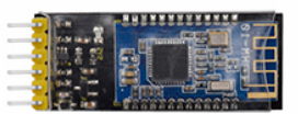
Specification
- Bluetooth protocol: Bluetooth Specification V4.0 BLE
- No byte limit in serial port Transceiving
- In open environment, realize 100m ultra-distance communication with iphone4s
- USB protocol: USB V2.0
- Working frequency: 2.4GHz ISM band
- Modulation method: GFSK(Gaussian Frequency Shift Keying)
- Transmission power: -23dbm, -6dbm, 0dbm, 6dbm, can be modified by AT command.
- Sensitivity: ≤-84dBm at 0.1% BER
- Transmission rate: Asynchronous: 6K bytes ; Synchronous: 6k Bytes
- Security feature: Authentication and encryption
- Supporting service: Central & Peripheral UUID FFE0, FFE1
- Power consumption: Auto sleep mode, stand by current 400uA~800uA, 8.5mA during transmission.
- Power supply: 5V DC
- Working temperature: –5 to +65 Centigrade
Bluetooth Control Key Test
Description
Next, we are going to introduce the use method for HC-06 Bluetooth module. To easily use the HC-06 Bluetooth module to control the robot arm, we particularly design the APP control. Shown below.
There are 10 control keys on the App. When connect well the HC-06 Bluetooth module to Android phone using our APP, press the control key, Android phone will receive a corresponding value.When programming, you can set the function for the corresponding value. So in the experiment, we will test each key to get the corresponding value.
Installation Steps for Android system:
You can download the APP from the link:
https://play.google.com/store/apps/details?id=com.keyestudio.keyes_arm_123
APP for Android mobile(overseas):
Enter google play,search “keyes arm”
https://play.google.com/store/apps/details?id=com.keyestudio.keyes_arm_123
APP for Android mobile(domestic):
Download link:https://pan.baidu.com/s/12vHhy8FulI9Y3osTDyZMMw
Note:this are operating steps as below, the interface for Android and ios system is same.
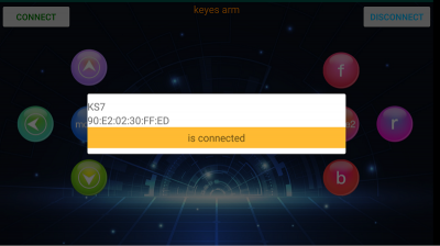
1.Download and install  ,the interface shown below:
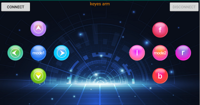
2.Upload code and power on, Led blinks. Start Bluetooth and open App to click “CONNECT” to connect.
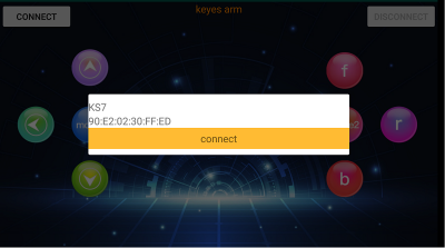
3.Upload code on control board, after power-on, LED blinks on Bluetooth module. Start Bluetooth and open App to click “connect”, Bluetooth is connected.
For IOS system:
1.Open App Store 
2.Search “keyes arm”on APP Store,then click “downlaod”.
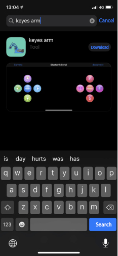
Special Note: Remove the Bluetooth module please, when uploading the Test Code, otherwise upload will fail. After uploading the Test Code, then connect the Bluetooth and Bluetooth module to pair.
Test Code
void setup()
{
  Serial.begin(9600);     //set baud rate to 9600
}

void loop()
{
  char val;    //define a variable to receive the data read by Bluetooth
  if(Serial.available())     // determine whether data is received
  {
val = Serial.read();       //the read data is assigned to “val”    Serial.println(val);
  }
}
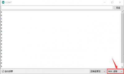
After connecting Bluetooth module, open serial port monitor to set baud rate to 9600. Press control keys on App, the serial port prints out the corresponding control character. As shown below:
Test Result:
The functions of control keys:
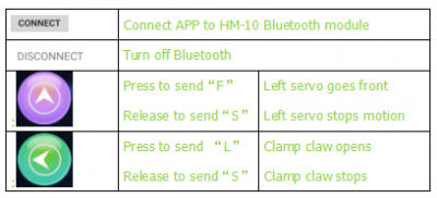
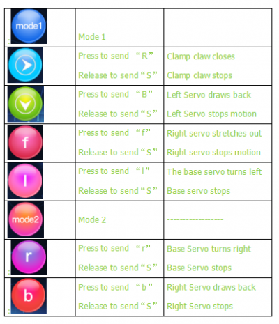
Bluetooth Controlling Robotic Arm
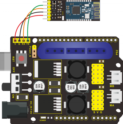
Description We introduced the control method of the 4-DOF robot arm and HM-10 Bluetooth module. In this experiment, we’ll control 4DOF robotic arm movement via APP.
Note: After uploading test code successfully, unplug the USB data cable and power up via external power supply and control 4 DOF robot arm movement via APP.
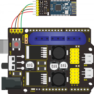
Connection Diagram
Test Code
#include <Servo.h>  //add Servo library files
Servo myservo1;  // create servo object to control a servo
Servo myservo2;
Servo myservo3;
Servo myservo4;
int pos1=90, pos2=60, pos3=130, pos4=0;  // define the variables of 4 Servo angle and assign initial values(posture angle values of boot-up)
char val;


void setup()
{
   //posture of boot-up
  myservo1.write(pos1);
  myservo2.write(pos2);
  myservo3.write(pos3);
  myservo4.write(pos4);
  delay(1500);

  Serial.begin(9600); //  set baud rate to 9600
}

void loop()
{
  myservo1.attach(A1);  //set control pin of servo1 to A1
  myservo2.attach(A0);  //set control pin of servo2 to A0
  myservo3.attach(8);   //set control pin of servo3 to D8
  myservo4.attach(9);   //set control pin of servo4 to D9

  if(Serial.available())   //determine if data is received
  {
    val=Serial.read();    //read the received data
    Serial.println(val);
  }
  switch(val)
    {
      case 'L':  arm_open();  break;   //claw opens
      case 'R':  arm_close();  break;   //claw closes
      case 'F':  left_f();  break;   //left servo swings forward
      case 'B':  left_b();  break;   //left servo swings back ward
      case 'f':  right_f();  break;   //right servo stretches out
      case 'b':  right_b();  break;   //right servo draws back
      case 'l':  T_left();  break;  //base servo turns left
      case 'r':  T_right();  break;  //base servo turns right
    }
}
//**************************************************
//turn left
void T_left()
{
    pos1=pos1+1;
    myservo1.write(pos1);
    delay(5);
    if(pos1>180)
    {
      pos1=180;
    }
}
//turn right
void T_right()
{
    pos1=pos1-1;
    myservo1.write(pos1);
    delay(5);
    if(pos1<1)
    {
      pos1=1;
    }
}
//********************************************
//claw closes
void arm_close()
{
      pos4=pos4-1;
      Serial.println(pos4);
      myservo4.write(pos4);
      delay(5);
      if(pos4<0)
      {
        pos4=0;
      }
}
//claw opens
void arm_open()
{
    pos4=pos4+1;
      Serial.println(pos4);
      myservo4.write(pos4);
      delay(5);
      if(pos4>108)
      {
        pos4=108;
      }
}

//******************************************
//left servo forward
void left_f()
{
    pos2=pos2-1;
    myservo2.write(pos2);
    delay(5);
    if(pos2<0)
    {
      pos2=0;
    }
}
//left servo backward
void left_b()
{
    pos2=pos2+1;
    myservo2.write(pos2);
    delay(5);
    if(pos2>180)
    {
      pos2=180;
    }
}

//***************************************
//right servo forward
void right_f()
{
  pos3=pos3+1;
    myservo3.write(pos3);
    delay(5);
    if(pos3>180)
    {
      pos3=180;
    }
}
//right servo backward
void right_b()
{
  pos3=pos3-1;
    myservo3.write(pos3);
    delay(5);
    if(pos3<35)
    {
      pos3=35;
    }
}
Test Result Uploading Test Code,wire and power on, pair Bluetooth successfully. Control 4DOF robotic arm movement via App.
Project 8: PS2 Controlling Robotic Arm (Extension)
PS2 Joypad Keys Test
Description
The shield comes with a PS2 Joypad connector which help you control robotic arm easily. The PS2 Joypad( PS2 receiver)is not included in kit. You need to purchase it online.
Firstly plug the PS2 receiver into the PS2 interface of the servo driver shield and then connect the PS2 Joypad. After the PS2 handle is connected well, upload code to test on Arduino IDE. Before testing, we need to put the PS2X_lib folder in the libraries folder where the Arduino IDE is installed. After uploading the sample code of PPS2X_lib folder, open the serial monitor, connect the PS2 Joypad, and press each button of the PS2 Joypad to view the characters printed on monitor.
Test Code
#include <PS2X_lib.h>  //for v1.6

/******************************************************************
 * set pins connected to PS2 controller:
 *   - 1e column: original
 *   - 2e colmun: Stef?
 * replace pin numbers by the ones you use
 ******************************************************************/
#define PS2_DAT        13  //14
#define PS2_CMD        11  //15
#define PS2_SEL        10  //16
#define PS2_CLK        12  //17

/******************************************************************
 * select modes of PS2 controller:
 *   - pressures = analog reading of push-butttons
 *   - rumble    = motor rumbling
 * uncomment 1 of the lines for each mode selection
 ******************************************************************/
//#define pressures   true
#define pressures   false
//#define rumble      true
#define rumble      false

PS2X ps2x; // create PS2 Controller Class

//right now, the library does NOT support hot pluggable controllers, meaning
//you must always either restart your Arduino after you connect the controller,
//or call config_gamepad(pins) again after connecting the controller.

int error = 0;
byte type = 0;
byte vibrate = 0;

void setup(){

  Serial.begin(57600);

  delay(300);  //added delay to give wireless ps2 module some time to startup, before configuring it

  //CHANGES for v1.6 HERE!!! **************PAY ATTENTION*************

  //setup pins and settings: GamePad(clock, command, attention, data, Pressures?, Rumble?) check for error
  error = ps2x.config_gamepad(PS2_CLK, PS2_CMD, PS2_SEL, PS2_DAT, pressures, rumble);

  if(error == 0){
    Serial.print("Found Controller, configured successful ");
    Serial.print("pressures = ");
  if (pressures)
    Serial.println("true ");
  else
    Serial.println("false");
  Serial.print("rumble = ");
  if (rumble)
    Serial.println("true)");
  else
    Serial.println("false");
    Serial.println("Try out all the buttons, X will vibrate the controller, faster as you press harder;");
    Serial.println("holding L1 or R1 will print out the analog stick values.");
    Serial.println("Note: Go to www.billporter.info for updates and to report bugs.");
  }
  else if(error == 1)
    Serial.println("No controller found, check wiring, see readme.txt to enable debug. visit www.billporter.info for troubleshooting tips");

  else if(error == 2)
    Serial.println("Controller found but not accepting commands. see readme.txt to enable debug. Visit www.billporter.info for troubleshooting tips");

  else if(error == 3)
    Serial.println("Controller refusing to enter Pressures mode, may not support it. ");

//  Serial.print(ps2x.Analog(1), HEX);

  type = ps2x.readType();
  switch(type) {
    case 0:
      Serial.print("Unknown Controller type found ");
      break;
    case 1:
      Serial.print("DualShock Controller found ");
      break;
    case 2:
      Serial.print("GuitarHero Controller found ");
      break;
  case 3:
      Serial.print("Wireless Sony DualShock Controller found ");
      break;
   }
}

void loop() {
  /* You must Read Gamepad to get new values and set vibration values
     ps2x.read_gamepad(small motor on/off, larger motor strenght from 0-255)
     if you don't enable the rumble, use ps2x.read_gamepad(); with no values
     You should call this at least once a second
   */
  if(error == 1) //skip loop if no controller found
    return;

  if(type == 2){ //Guitar Hero Controller
    ps2x.read_gamepad();          //read controller

    if(ps2x.ButtonPressed(GREEN_FRET))
      Serial.println("Green Fret Pressed");
    if(ps2x.ButtonPressed(RED_FRET))
      Serial.println("Red Fret Pressed");
    if(ps2x.ButtonPressed(YELLOW_FRET))
      Serial.println("Yellow Fret Pressed");
    if(ps2x.ButtonPressed(BLUE_FRET))
      Serial.println("Blue Fret Pressed");
    if(ps2x.ButtonPressed(ORANGE_FRET))
      Serial.println("Orange Fret Pressed");

    if(ps2x.ButtonPressed(STAR_POWER))
      Serial.println("Star Power Command");

    if(ps2x.Button(UP_STRUM))          //will be TRUE as long as button is pressed
      Serial.println("Up Strum");
    if(ps2x.Button(DOWN_STRUM))
      Serial.println("DOWN Strum");

    if(ps2x.Button(PSB_START))         //will be TRUE as long as button is pressed
      Serial.println("Start is being held");
    if(ps2x.Button(PSB_SELECT))
      Serial.println("Select is being held");

    if(ps2x.Button(ORANGE_FRET)) {     // print stick value IF TRUE
      Serial.print("Wammy Bar Position:");
      Serial.println(ps2x.Analog(WHAMMY_BAR), DEC);
    }
  }
  else { //DualShock Controller
    ps2x.read_gamepad(false, vibrate); //read controller and set large motor to spin at 'vibrate' speed

    if(ps2x.Button(PSB_START))         //will be TRUE as long as button is pressed
      Serial.println("Start is being held");
    if(ps2x.Button(PSB_SELECT))
      Serial.println("Select is being held");

    if(ps2x.Button(PSB_PAD_UP)) {      //will be TRUE as long as button is pressed
      Serial.print("Up held this hard: ");
      Serial.println(ps2x.Analog(PSAB_PAD_UP), DEC);
    }
    if(ps2x.Button(PSB_PAD_RIGHT)){
      Serial.print("Right held this hard: ");
      Serial.println(ps2x.Analog(PSAB_PAD_RIGHT), DEC);
    }
    if(ps2x.Button(PSB_PAD_LEFT)){
      Serial.print("LEFT held this hard: ");
      Serial.println(ps2x.Analog(PSAB_PAD_LEFT), DEC);
    }
    if(ps2x.Button(PSB_PAD_DOWN)){
      Serial.print("DOWN held this hard: ");
      Serial.println(ps2x.Analog(PSAB_PAD_DOWN), DEC);
    }

    vibrate = ps2x.Analog(PSAB_CROSS);  //this will set the large motor vibrate speed based on how hard you press the blue (X) button
    if (ps2x.NewButtonState()) {        //will be TRUE if any button changes state (on to off, or off to on)
      if(ps2x.Button(PSB_L3))
        Serial.println("L3 pressed");
      if(ps2x.Button(PSB_R3))
        Serial.println("R3 pressed");
      if(ps2x.Button(PSB_L2))
        Serial.println("L2 pressed");
      if(ps2x.Button(PSB_R2))
        Serial.println("R2 pressed");
      if(ps2x.Button(PSB_TRIANGLE))
        Serial.println("Triangle pressed");
    }

    if(ps2x.ButtonPressed(PSB_CIRCLE))               //will be TRUE if button was JUST pressed
      Serial.println("Circle just pressed");
    if(ps2x.NewButtonState(PSB_CROSS))              //will be TRUE if button was JUST pressed OR released
      Serial.println("X just changed");
    if(ps2x.ButtonReleased(PSB_SQUARE))              //will be TRUE if button was JUST released
      Serial.println("Square just released");

    if(ps2x.Button(PSB_L1) || ps2x.Button(PSB_R1)) { //print stick values if either is TRUE
      Serial.print("Stick Values:");
      Serial.print(ps2x.Analog(PSS_LY), DEC); //Left stick, Y axis. Other options: LX, RY, RX
      Serial.print(",");
      Serial.print(ps2x.Analog(PSS_LX), DEC);
      Serial.print(",");
      Serial.print(ps2x.Analog(PSS_RY), DEC);
      Serial.print(",");
      Serial.println(ps2x.Analog(PSS_RX), DEC);
    }
  }
  delay(50);
}
Test Result:
Stack the drive shield onto REV4 and upload the code. Connecting the PS2 Joypad, open the serial monitor and set the baud rate to 57600. When press down the key or push the rocker, you could see the corresponding character showed on the monitor.
PS2 Joypad Control
Description:
In the previous section, we have showed how to use Joystick module to control the robot arm. It is almost the same for you to control the 4DOF robot arm using the PS2 Joypad.
Test Code
#include <PS2X_lib.h>

PS2X ps2x; // create PS2 Controller Class


//right now, the library does NOT support hot pluggable controllers, meaning
//you must always either restart your Arduino after you connect the controller,
//or call config_gamepad(pins) again after connecting the controller.
int error = 0;
byte vibrate = 0;

#include <Servo.h>  // add the servo libraries
Servo myservo1;  // create servo object to control a servo
Servo myservo2;
Servo myservo3;
Servo myservo4;

int pos1=90, pos2=60, pos3=130, pos4=0;  // define the variable of 4 servo angle and assign the initial value( that is the boot posture angle value)

void setup(){
 Serial.begin(57600);

// boot posture
  myservo1.write(pos1);
  delay(1000);
  myservo2.write(pos2);
  myservo3.write(pos3);
  myservo4.write(pos4);
  delay(1500);

 error = ps2x.config_gamepad(13,11,10,12);   //setup GamePad(clock, command, attention, data) pins, check for error

 if(error == 0){
   Serial.println("Found Controller, configured successful");
   Serial.println("Try out all the buttons, X will vibrate the controller, faster as you press harder;");
  Serial.println("holding L1 or R1 will print out the analog stick values.");
  Serial.println("Go to www.billporter.info for updates and to report bugs.");
 }

  else if(error == 1)
   Serial.println("No controller found, check wiring, see readme.txt to enable debug. visit www.billporter.info for troubleshooting tips");

  else if(error == 2)
   Serial.println("Controller found but not accepting commands. see readme.txt to enable debug. Visit www.billporter.info for troubleshooting tips");

   //Serial.print(ps2x.Analog(1), HEX);


 ps2x.enableRumble();              //enable rumble vibration motors
 ps2x.enablePressures();           //enable reading the pressure values from the buttons.


}

void loop(){
   /* You must Read Gamepad to get new values
   Read GamePad and set vibration values
   ps2x.read_gamepad(small motor on/off, larger motor strenght from 0-255)
   if you don't enable the rumble, use ps2x.read_gamepad(); with no values

   you should call this at least once a second
   */

  myservo1.attach(A1);  // set the control pin of servo 1 to A1
  myservo2.attach(A0);  // set the control pin of servo 2 to A0
  myservo3.attach(8);   // set the control pin of servo 3 to D6
  myservo4.attach(9);   // set the control pin of servo 4 to D9

 if(error != 0)
  return;

  ps2x.read_gamepad(false, vibrate);          //read controller and set large motor to spin at 'vibrate' speed

  if(ps2x.Button(PSB_START))                   //will be TRUE as long as button is pressed
       Serial.println("Start is being held");
  if(ps2x.Button(PSB_SELECT))
       Serial.println("Select is being held");


   if(ps2x.Button(PSB_PAD_UP)) {         //will be TRUE as long as button is pressed
     Serial.print("Up held this hard: ");
     Serial.println(ps2x.Analog(PSAB_PAD_UP), DEC);
    }
    if(ps2x.Button(PSB_PAD_RIGHT)){
     Serial.print("Right held this hard: ");
      Serial.println(ps2x.Analog(PSAB_PAD_RIGHT), DEC);
    }
    if(ps2x.Button(PSB_PAD_LEFT)){
     Serial.print("LEFT held this hard: ");
      Serial.println(ps2x.Analog(PSAB_PAD_LEFT), DEC);
    }
    if(ps2x.Button(PSB_PAD_DOWN)){
     Serial.print("DOWN held this hard: ");
   Serial.println(ps2x.Analog(PSAB_PAD_DOWN), DEC);
    }


    vibrate = ps2x.Analog(PSAB_BLUE);        //this will set the large motor vibrate speed based on
                                            //how hard you press the blue (X) button

  if (ps2x.NewButtonState())               //will be TRUE if any button changes state (on to off, or off to on)
  {
      if(ps2x.Button(PSB_R3))

       Serial.println("R3 pressed");


      if(ps2x.Button(PSB_L3))
       Serial.println("L3 pressed");

      if(ps2x.Button(PSB_L2))
       Serial.println("L2 pressed");
      if(ps2x.Button(PSB_R2))
       Serial.println("R2 pressed");
      if(ps2x.Button(PSB_GREEN))
       Serial.println("Triangle pressed");

  }


  if(ps2x.ButtonPressed(PSB_RED))             //will be TRUE if button was JUST pressed
       Serial.println("Circle just pressed");

  if(ps2x.ButtonReleased(PSB_PINK))             //will be TRUE if button was JUST released
       Serial.println("Square just released");

  if(ps2x.NewButtonState(PSB_BLUE))            //will be TRUE if button was JUST pressed OR released
       Serial.println("X just changed");

    //rotate
    zhuandong();
    //clamp claw
    zhuazi();
    //main arm
    dabi();
    //forearm
    xiaobi();

  if(ps2x.Button(PSB_L1) || ps2x.Button(PSB_R1)) // print stick values if either is TRUE
  {
      Serial.print("Stick Values:");
      Serial.print(ps2x.Analog(PSS_LY), DEC); //Left stick, Y axis. Other options: LX, RY, RX
      Serial.print(",");
      Serial.print(ps2x.Analog(PSS_LX), DEC);
      Serial.print(",");
      Serial.print(ps2x.Analog(PSS_RY), DEC);
      Serial.print(",");
      Serial.println(ps2x.Analog(PSS_RX), DEC);
  }
  delay(5);
}
//********************************************************************
// turn
void zhuandong()
{
//turn right
   if(ps2x.Analog (PSS_RX) > 200)  // if push the right joystick to the right
    {
      //Serial.println(ps2x.Analog(PSS_RX), DEC);
      pos1=pos1-1;    //pos1 subtracts 1
      myservo1.write(pos1);   // servo 1 executes the action, the arm will turn right.
      // delay(5);
      if(pos1<1)   // limit the right turning angle
      {
        pos1=1;
      }
     }
      // turn left
     if(ps2x.Analog (PSS_RX) < 50)    // if push the right joystick to the left
     {
       //Serial.println(ps2x.Analog(PSS_RX), DEC);
       pos1=pos1+1;   //pos1 plus 1
       myservo1.write(pos1);     // the arm turns left
       // delay(5);
       if(pos1>180)     // limit the left turning angle
       {
         pos1=180;
       }
     }
 }
 //**********************************************************************
 // upper arm
void xiaobi()
{
  //upper arm front
   if(ps2x.Analog(PSS_RY)<50)  // if push the right joystick upward
   {
      pos2=pos2-1;
      myservo2.write(pos2);    // the upper arm will lift
      delay(5);
      if(pos2<0)    // limit the lifting angle
      {
        pos2=0;
      }
    }
    //upper arm back
    if(ps2x.Analog(PSS_RY)>200)    // if push the right joystick downward
    {
      pos2=pos2+1;
      myservo2.write(pos2);   // the upper arm will go down
      delay(5);
      if(pos2>180)  // limit the declining angle
      {
        pos2=180;
      }
    }
}
//***************************************************************
void zhuazi()
{
// close the claw
   if(ps2x.Analog(PSS_LX)>220)   // if push the left joystick to the right
   {
      pos4=pos4-1;
      Serial.println(pos4);
      myservo4.write(pos4);  // servo 4 carries out the action and the claw is gradually closed.
      delay(5);
      if(pos4<0)   // if pos4 value subtracts to 37, the claw in 37 degrees we have tested is closed.)
      {
        pos4=0;
      }
    }
    // open the claw
    if(ps2x.Analog(PSS_LX)<10)   // if push the left joystick to the left
    {
      pos4=pos4+8;
      Serial.println(pos4);
      myservo4.write(pos4);   // servo 4 carries out the action and the claw is gradually opened
      delay(5);
      if(pos4>108)    // limit the maximum opening angle
      {
        pos4=108;
      }
    }
}
//*********************************************************
void dabi()
{
  // lower arm front
  if(ps2x.Analog(PSS_LY)>200)  // if push the left joystick upward
  {
    pos3=pos3+1;
    myservo3.write(pos3);  // the lower arm will stretch out
    delay(5);
    if(pos3>180)   // limit the stretched angle
    {
      pos3=180;
    }
   }
  if(ps2x.Analog(PSS_LY)<10)    //if push the left joystick downward
  {
    pos3=pos3-1;
    myservo3.write(pos3);   // the lower arm will draw back
    delay(5);
    if(pos3<35)    // limit the retracted angle
    {
      pos3=35;
    }
   }
}
Test Result:
Stack the shield onto REV4 and upload the code. Powered on and connected the PS2 Joypad, you can use the PS2 Joypad to control the robot arm actions.
PS2 Controlling Posture Memory
Description:
In the previous experiment, we have showed how to use Joystick module to control the robot arm memorize several postures. Now we replace the joystick module with PS2 Joypad. The program thought is almost the same.
Test Code
#include <PS2X_lib.h>
#include <Servo.h>  // add the servo libraries
Servo myservo1;  // create servo object to control a servo
Servo myservo2;
Servo myservo3;
Servo myservo4;

int pos1=90, pos2=60, pos3=130, pos4=0;  // define the variable of 4 servo angle and assign the initial value( that is the boot posture angle value)

PS2X ps2x; // create PS2 Controller Class

//right now, the library does NOT support hot pluggable controllers, meaning
//you must always either restart your Arduino after you conect the controller,
//or call config_gamepad(pins) again after connecting the controller.
int error = 0;
byte vibrate = 0;

int s1,s2,s3,s4;
int jiyi1[20];  // define four array, separately used to save the angle of 4 servos.
int jiyi2[20];
int jiyi3[20];
int jiyi4[20];
int i=0;
int j=0;

void setup()
{
 Serial.begin(57600);

 // boot posture
  myservo1.write(pos1);
  delay(1000);
  myservo2.write(pos2);
  myservo3.write(pos3);
  myservo4.write(pos4);
  delay(1500);


 error = ps2x.config_gamepad(13,11,10,12);   //setup GamePad(clock, command, attention, data) pins, check for error

 if(error == 0){
   Serial.println("Found Controller, configured successful");
   Serial.println("Try out all the buttons, X will vibrate the controller, faster as you press harder;");
  Serial.println("holding L1 or R1 will print out the analog stick values.");
  Serial.println("Go to www.billporter.info for updates and to report bugs.");
 }

  else if(error == 1)
   Serial.println("No controller found, check wiring, see readme.txt to enable debug. visit www.billporter.info for troubleshooting tips");

  else if(error == 2)
   Serial.println("Controller found but not accepting commands. see readme.txt to enable debug. Visit www.billporter.info for troubleshooting tips");

   //Serial.print(ps2x.Analog(1), HEX);


 ps2x.enableRumble();              //enable rumble vibration motors
 ps2x.enablePressures();           //enable reading the pressure values from the buttons.


}

void loop()
{
  myservo1.attach(A1);  // set the control pin of servo 1 to A1
  myservo2.attach(A0);  // set the control pin of servo 2 to A0
  myservo3.attach(8);   // set the control pin of servo 3 to D6
  myservo4.attach(9);   // set the control pin of servo 4 to D9

 if(error != 0)
  return;

  ps2x.read_gamepad(false, vibrate);          //read controller and set large motor to spin at 'vibrate' speed

  if(ps2x.Button(PSB_START))                   //will be TRUE as long as button is pressed
       Serial.println("Start is being held");
  if(ps2x.Button(PSB_SELECT))
       Serial.println("Select is being held");


   if(ps2x.Button(PSB_PAD_UP)) {         //will be TRUE as long as button is pressed
     Serial.print("Up held this hard: ");
     Serial.println(ps2x.Analog(PSAB_PAD_UP), DEC);
    }
    if(ps2x.Button(PSB_PAD_RIGHT)){
     Serial.print("Right held this hard: ");
      Serial.println(ps2x.Analog(PSAB_PAD_RIGHT), DEC);
    }
    if(ps2x.Button(PSB_PAD_LEFT)){
     Serial.print("LEFT held this hard: ");
      Serial.println(ps2x.Analog(PSAB_PAD_LEFT), DEC);
    }
    if(ps2x.Button(PSB_PAD_DOWN)){
     Serial.print("DOWN held this hard: ");
   Serial.println(ps2x.Analog(PSAB_PAD_DOWN), DEC);
    }


    vibrate = ps2x.Analog(PSAB_BLUE);        //this will set the large motor vibrate speed based on
                                            //how hard you press the blue (X) button

  if (ps2x.NewButtonState())               //will be TRUE if any button changes state (on to off, or off to on)
  {
      if(ps2x.Button(PSB_R3))
      {
        //Serial.println("R3 pressed");
        // record
        s1=myservo1.read();
        delay(100);
        Serial.println(s1);
        s2=myservo2.read();
        delay(100);
        Serial.println(s2);
        s3=myservo3.read();
        delay(100);
        Serial.println(s3);
        s4=myservo4.read();
        delay(100);
        Serial.println(s4);

        jiyi1[i]=s1;  // save the servo value read in the array sequentially
        jiyi2[i]=s2;
        jiyi3[i]=s3;
        jiyi4[i]=s4;
        i++;
        j=i;
       // delay(100);
       Serial.println(i);
      }

      if(ps2x.Button(PSB_L3))
      {
        //Serial.println("L3 pressed");
        i=0;
   //perform
       pos1 = myservo1.read();
       pos2 = myservo2.read();
       pos3 = myservo3.read();
       pos4 = myservo4.read();

      for(int k=0;k<j;k++)  //for loop, to execute all the stored actions
      {
        if(pos1<jiyi1[k])  //if the current servo 1 angle is less than the value stored in array 1.
        {
          while(pos1<jiyi1[k])  //while loop, make servo turn to the position of value stored in the array.
          {
            myservo1.write(pos1);   // servo 1 executes the action
            delay(5);   // delay 5ms,controlling the rotating speed of servo
            pos1++;
            //Serial.println(pos1);
          }
        }
        else   //if the current servo 1 angle is greater than the value stored in array 1.
        {
         while(pos1>jiyi1[k])  //while loop, make servo turn to the position of value stored in the array.
          {
            myservo1.write(pos1);   // servo 1 executes the action
            delay(5);    //delay 5ms,controlling the rotating speed of servo
            pos1--;
            //Serial.println(pos1);
          }

//**********************************************
// the same analysis as the previous servo
        if(pos2<jiyi2[k])
        {
          while(pos2<jiyi2[k])
          {
            myservo2.write(pos2);
            delay(5);
            pos2++;
            //Serial.println(pos1);
          }
        }
        else
        {
         while(pos2>jiyi2[k])
          {
            myservo2.write(pos2);
            delay(5);
            pos2--;
            //Serial.println(pos1);
          }
        }
 //*****************************************************
 //the same analysis
        if(pos3<jiyi3[k])
        {
          while(pos3<jiyi3[k])
          {
            myservo3.write(pos3);
            delay(5);
            pos3++;
            //Serial.println(pos1);
          }
        }
        else
        {
         while(pos3>jiyi3[k])
          {
            myservo3.write(pos3);
            delay(5);
            pos3--;
            //Serial.println(pos1);
          }
        }
 //*****************************************************
 //the same analysis
        if(pos4<jiyi4[k])
        {
          while(pos4<jiyi4[k])
          {
            myservo4.write(pos4);
            delay(5);
            pos4++;
            //Serial.println(pos1);
          }
        }
        else
        {
         while(pos4>jiyi4[k])
          {
            myservo4.write(pos4);
            delay(5);
            pos4--;
            //Serial.println(pos1);
          }
        }
      }
    }
      }


      if(ps2x.Button(PSB_L2))
       Serial.println("L2 pressed");
      if(ps2x.Button(PSB_R2))
       Serial.println("R2 pressed");
      if(ps2x.Button(PSB_GREEN))
       Serial.println("Triangle pressed");

  }


  if(ps2x.ButtonPressed(PSB_RED))             //will be TRUE if button was JUST pressed
       Serial.println("Circle just pressed");

  if(ps2x.ButtonReleased(PSB_PINK))             //will be TRUE if button was JUST released
       Serial.println("Square just released");

  if(ps2x.NewButtonState(PSB_BLUE))            //will be TRUE if button was JUST pressed OR released
       Serial.println("X just changed");

    // turn
    zhuandong();
    // claw
    zhuazi();
    // lower arm
    dabi();
    // upper arm
    xiaobi();

  if(ps2x.Button(PSB_L1) || ps2x.Button(PSB_R1)) // print stick values if either is TRUE
  {
      Serial.print("Stick Values:");
      Serial.print(ps2x.Analog(PSS_LY), DEC); //Left stick, Y axis. Other options: LX, RY, RX
      Serial.print(",");
      Serial.print(ps2x.Analog(PSS_LX), DEC);
      Serial.print(",");
      Serial.print(ps2x.Analog(PSS_RY), DEC);
      Serial.print(",");
      Serial.println(ps2x.Analog(PSS_RX), DEC);
  }

 delay(5);
}

//********************************************************************
// turn
void zhuandong()
{
//turn right
   if(ps2x.Analog (PSS_RX) > 200)  // if push the right joystick to the right
    {
      //Serial.println(ps2x.Analog(PSS_RX), DEC);
      pos1=pos1-1;    //pos1 subtracts 1
      myservo1.write(pos1);   // servo 1 carries out the action and the arm will turn right
      // delay(5);
      if(pos1<1)   // limit the right turning angle
      {
        pos1=1;
      }
     }
      //turn left
     if(ps2x.Analog (PSS_RX) < 50)    //if push the right joystick to the left
     {
       //Serial.println(ps2x.Analog(PSS_RX), DEC);
       pos1=pos1+1;   //pos1 plus 1
       myservo1.write(pos1);     // the arm will turn left
       // delay(5);
       if(pos1>180)     // limit the left turning angle
       {
         pos1=180;
       }
     }
 }
 //**********************************************************************
 // upper arm
void xiaobi()
{
  //upper arm front
   if(ps2x.Analog(PSS_RY)<50)  // if push the right joystick upward
   {
      pos2=pos2-1;
      myservo2.write(pos2);    // the upper arm will lift up
      delay(5);
      if(pos2<0)    // limit the lifting angle
      {
        pos2=0;
      }
    }
    // upper arm back
    if(ps2x.Analog(PSS_RY)>200)    //if push the right joystick downward
    {
      pos2=pos2+1;
      myservo2.write(pos2);   // the upper arm will go down
      delay(5);
      if(pos2>180)  // limit the declining angle
      {
        pos2=180;
      }
    }
}
//***************************************************************
void zhuazi()
{
// close the claw
   if(ps2x.Analog(PSS_LX)>220)   // if push the left joystick to the right
   {
      pos4=pos4-1;
      Serial.println(pos4);
      myservo4.write(pos4);  // servo 4 carries out the action and the claw is gradually closed.
      delay(5);
      if(pos4<0)   // if pos4 value reduces to 37(the claw we test in 37degrees is closed)
      {
        pos4=0;
      }
    }
    // open the claw
    if(ps2x.Analog(PSS_LX)<10)   // if push the left joystick to the left
    {
      pos4=pos4+8;
      Serial.println(pos4);
      myservo4.write(pos4);   // servo 4 carries out the action and the claw is gradually opened
      delay(5);
      if(pos4>108)    // limit the maximum angle opened
      {
        pos4=108;
      }
    }
}
//*********************************************************
void dabi()
{
  // lower arm front
  if(ps2x.Analog(PSS_LY)>200)  //  if push the left joystick upward
  {
    pos3=pos3+1;
    myservo3.write(pos3);  // the lower arm will stretch out
    delay(5);
    if(pos3>180)   // limit the stretched angle
    {
      pos3=180;
    }
   }
  if(ps2x.Analog(PSS_LY)<10)    // if push the left joystick downward
  {
    pos3=pos3-1;
    myservo3.write(pos3);   //the lower arm will retract
    delay(5);
    if(pos3<35)    // limit the retracted angle
    {
      pos3=35;
    }
   }
}
Test Result:
Stack the shield onto REV4 and upload the code. Powered on and connected the PS2 Joypad, you can use the PS2 Joypad to control the robot arm memorize several postures.
PS2 Controlling Posture Memory And Loop
Description:
In the previous experiment, we have showed how to use Joystick module to control the robot arm memorize several postures and loop. Now we replace the Joystick module with the PS2 Joypad. The program is almost the same.
Test Code
#include <PS2X_lib.h>
#include <Servo.h>  // add the servo libraries
Servo myservo1;  // create servo object to control a servo
Servo myservo2;
Servo myservo3;
Servo myservo4;

int pos1=90, pos2=60, pos3=130, pos4=0;  // define the variable of 4 servo angle and assign the initial value( that is the boot posture angle value)

PS2X ps2x; // create PS2 Controller Class

//right now, the library does NOT support hot pluggable controllers, meaning
//you must always either restart your Arduino after you conect the controller,
//or call config_gamepad(pins) again after connecting the controller.
int error = 0;
byte vibrate = 0;

int s1,s2,s3,s4;
int jiyi1[30];   //define four array, separately used to save the angle of 4 servos.
int jiyi2[30];
int jiyi3[30];
int jiyi4[30];
int i=0;
int j=0,tt=0;
void setup()
{
 Serial.begin(57600);

 // boot posture
  myservo1.write(pos1);
  delay(1000);
  myservo2.write(pos2);
  myservo3.write(pos3);
  myservo4.write(pos4);
  delay(1500);


 error = ps2x.config_gamepad(13,11,10,12);   //setup GamePad(clock, command, attention, data) pins, check for error

 if(error == 0){
   Serial.println("Found Controller, configured successful");
   Serial.println("Try out all the buttons, X will vibrate the controller, faster as you press harder;");
  Serial.println("holding L1 or R1 will print out the analog stick values.");
  Serial.println("Go to www.billporter.info for updates and to report bugs.");
 }

  else if(error == 1)
   Serial.println("No controller found, check wiring, see readme.txt to enable debug. visit www.billporter.info for troubleshooting tips");

  else if(error == 2)
   Serial.println("Controller found but not accepting commands. see readme.txt to enable debug. Visit www.billporter.info for troubleshooting tips");

   //Serial.print(ps2x.Analog(1), HEX);


 ps2x.enableRumble();              //enable rumble vibration motors
 ps2x.enablePressures();           //enable reading the pressure values from the buttons.
}

void loop()
{
  myservo1.attach(A1);  // set the control pin of servo 1 to A1
  myservo2.attach(A0);  //set the control pin of servo 2 to A0
  myservo3.attach(8);   //set the control pin of servo 3 to D6
  myservo4.attach(9);   //set the control pin of servo 4 to D9

 if(error != 0)
  return;

  ps2x.read_gamepad(false, vibrate);          //read controller and set large motor to spin at 'vibrate' speed

  if(ps2x.Button(PSB_START))                   //will be TRUE as long as button is pressed
       Serial.println("Start is being held");
  if(ps2x.Button(PSB_SELECT))
       Serial.println("Select is being held");


   if(ps2x.Button(PSB_PAD_UP)) {         //will be TRUE as long as button is pressed
     Serial.print("Up held this hard: ");
     Serial.println(ps2x.Analog(PSAB_PAD_UP), DEC);
    }
    if(ps2x.Button(PSB_PAD_RIGHT)){
     Serial.print("Right held this hard: ");
      Serial.println(ps2x.Analog(PSAB_PAD_RIGHT), DEC);
    }
    if(ps2x.Button(PSB_PAD_LEFT)){
     Serial.print("LEFT held this hard: ");
      Serial.println(ps2x.Analog(PSAB_PAD_LEFT), DEC);
    }
    if(ps2x.Button(PSB_PAD_DOWN)){
     Serial.print("DOWN held this hard: ");
   Serial.println(ps2x.Analog(PSAB_PAD_DOWN), DEC);
    }


    vibrate = ps2x.Analog(PSAB_BLUE);        //this will set the large motor vibrate speed based on
                                            //how hard you press the blue (X) button

  if (ps2x.NewButtonState())               //will be TRUE if any button changes state (on to off, or off to on)
  {
      if(ps2x.Button(PSB_R3))
      {
        //Serial.println("R3 pressed");
        //record
        s1=myservo1.read();
        delay(100);
        Serial.println(s1);
        s2=myservo2.read();
        delay(100);
        Serial.println(s2);
        s3=myservo3.read();
        delay(100);
        Serial.println(s3);
        s4=myservo4.read();
        delay(100);
        Serial.println(s4);

        jiyi1[i]=s1;  //save the servo value read in the array sequentially
        jiyi2[i]=s2;
        jiyi3[i]=s3;
        jiyi4[i]=s4;
        i++;
        j=i;
       // delay(100);
       Serial.println(i);
      }

       // carry out
      if(ps2x.Button(PSB_L3))
      {
        //Serial.println("L3 pressed");
        i=0;
        tt=1;

       pos1 = myservo1.read();  // record the angle value of 4 servo posture
       pos2 = myservo2.read();
       pos3 = myservo3.read();
       pos4 = myservo4.read();

     while(tt==1)  // repeat the actions
     {
       for(int k=0;k<j;k++)   //for loop, to execute all the stored actions.
      {
        if(pos1<jiyi1[k])   // if the current servo 1 angle is less than the value stored in array 1.
        {
          while(pos1<jiyi1[k])    //while loop, make servo turn to the position of value stored in the array.
          {
            myservo1.write(pos1);   //servo 1 executes the action
            delay(5);     //delay 5ms,controlling the rotating speed of servo.
            pos1++;
            //Serial.println(pos1);
          }
        }
        else     //if the current servo 1 angle is greater than the value stored in array 1.
        {
         while(pos1>jiyi1[k])     //while loop, make servo turn to the position of value stored in the array.
          {
            myservo1.write(pos1);    //servo 1 executes the action
            delay(5);           //delay 5ms,controlling the rotating speed of servo.
            pos1--;
            //Serial.println(pos1);
          }

//**********************************************
// the same analysis as the previous servo
        if(pos2<jiyi2[k])
        {
          while(pos2<jiyi2[k])
          {
            myservo2.write(pos2);
            delay(5);
            pos2++;
            //Serial.println(pos1);
          }
        }
        else
        {
         while(pos2>jiyi2[k])
          {
            myservo2.write(pos2);
            delay(5);
            pos2--;
            //Serial.println(pos1);
          }
        }
 //*****************************************************
// the same analysis as the previous servo
        if(pos3<jiyi3[k])
        {
          while(pos3<jiyi3[k])
          {
            myservo3.write(pos3);
            delay(5);
            pos3++;
            //Serial.println(pos1);
          }
        }
        else
        {
         while(pos3>jiyi3[k])
          {
            myservo3.write(pos3);
            delay(5);
            pos3--;
            //Serial.println(pos1);
          }
        }
 //*****************************************************
// the same analysis as the previous servo
        if(pos4<jiyi4[k])
        {
          while(pos4<jiyi4[k])
          {
            myservo4.write(pos4);
            delay(5);
            pos4++;
            //Serial.println(pos1);
          }
        }
        else
        {
         while(pos4>jiyi4[k])
          {
            myservo4.write(pos4);
            delay(5);
            pos4--;
            //Serial.println(pos1);
          }
        }
      }
    }
    //*******************************************************
    // exit the looping
     ps2x.enableRumble();              //enable rumble vibration motors
     ps2x.enablePressures();
     ps2x.read_gamepad(false, vibrate);
     vibrate = ps2x.Analog(PSAB_BLUE);
      if (ps2x.NewButtonState())               //will be TRUE if any button changes state (on to off, or off to on)
      {
        if(ps2x.Button(PSB_R3))
        {
          tt=0;
          i=0;
          break;
        }
      }
   //*********************************************************
   }
  }

      if(ps2x.Button(PSB_L2))
       Serial.println("L2 pressed");
      if(ps2x.Button(PSB_R2))
       Serial.println("R2 pressed");
      if(ps2x.Button(PSB_GREEN))
       Serial.println("Triangle pressed");

  }


  if(ps2x.ButtonPressed(PSB_RED))             //will be TRUE if button was JUST pressed
       Serial.println("Circle just pressed");

  if(ps2x.ButtonReleased(PSB_PINK))             //will be TRUE if button was JUST released
       Serial.println("Square just released");

  if(ps2x.NewButtonState(PSB_BLUE))            //will be TRUE if button was JUST pressed OR released
       Serial.println("X just changed");

    //turn
    zhuandong();
    //claw
    zhuazi();
    // lower arm
    dabi();
    // upper arm
    xiaobi();

  if(ps2x.Button(PSB_L1) || ps2x.Button(PSB_R1)) // print stick values if either is TRUE
  {
      Serial.print("Stick Values:");
      Serial.print(ps2x.Analog(PSS_LY), DEC); //Left stick, Y axis. Other options: LX, RY, RX
      Serial.print(",");
      Serial.print(ps2x.Analog(PSS_LX), DEC);
      Serial.print(",");
      Serial.print(ps2x.Analog(PSS_RY), DEC);
      Serial.print(",");
      Serial.println(ps2x.Analog(PSS_RX), DEC);
  }

 delay(5);
}

//********************************************************************
// turn
void zhuandong()
{
// turn right
   if(ps2x.Analog (PSS_RX) > 200)  // if push the right joystick to the right
    {
      //Serial.println(ps2x.Analog(PSS_RX), DEC);
      pos1=pos1-1;    //pos1 subtracts 1
      myservo1.write(pos1);   // servo 1 carries out the action, the robot arm turns right.
      // delay(5);
      if(pos1<1)   // limit the right turning angle
      {
        pos1=1;
      }
     }
      // turn left
     if(ps2x.Analog (PSS_RX) < 50)    // if push the right joystick to the left
     {
       //Serial.println(ps2x.Analog(PSS_RX), DEC);
       pos1=pos1+1;   //pos1 plus 1
       myservo1.write(pos1);     // the robot arm turns left
       // delay(5);
       if(pos1>180)     // limit the left turning angle
       {
         pos1=180;
       }
     }
 }
 //**********************************************************************
 // the upper arm
void xiaobi()
{
  // upper arm front
   if(ps2x.Analog(PSS_RY)<50)  // if push the right joystick upward
   {
      pos2=pos2-1;
      myservo2.write(pos2);    // the upper arm will lift up
      delay(5);
      if(pos2<0)    // limit the lifting angle
      {
        pos2=0;
      }
    }
    // upper arm back
    if(ps2x.Analog(PSS_RY)>200)    //if push the right joystick to downward
    {
      pos2=pos2+1;
      myservo2.write(pos2);   // the robot arm will go down
      delay(5);
      if(pos2>180)  // limit the declining angle
      {
        pos2=180;
      }
    }
}
//***************************************************************
void zhuazi()
{
// close the claw
   if(ps2x.Analog(PSS_LX)>220)   // if push the left joystick to the right
   {
      pos4=pos4-1;
      Serial.println(pos4);
      myservo4.write(pos4);  // servo 4 carries out the action and claw is gradually closed
      delay(5);
      if(pos4<0)   // if pos4 value subtracts to 37, the claw in 37 degrees we have tested is closed.)
      {
        pos4=0;
      }
    }
    // open the claw
    if(ps2x.Analog(PSS_LX)<10)   //  if push the left joystick to the left
    {
      pos4=pos4+8;
      Serial.println(pos4);
      myservo4.write(pos4);   //  servo 4 carries out the action and claw is gradually opened
      delay(5);
      if(pos4>108)    // limit the maximum angle opened
      {
        pos4=108;
      }
    }
}
//*********************************************************
void dabi()
{
  // lower arm front
  if(ps2x.Analog(PSS_LY)>200)  // if push the left joystick upward
  {
    pos3=pos3+1;
    myservo3.write(pos3);  //  the lower arm will stretch out
    delay(5);
    if(pos3>180)   // limit the stretched angle
    {
      pos3=180;
    }
   }
  if(ps2x.Analog(PSS_LY)<10)    // if push the left joystick downward
  {
    pos3=pos3-1;
    myservo3.write(pos3);   // the lower arm will draw back
    delay(5);
    if(pos3<35)    //  limit the retracted angle
    {
      pos3=35;
    }
   }
}
Test Result:
Stack the shield onto REV4 and upload the code. Powered on and connected the PS2 Joypad, you can use the PS2 Joypad to control the robot arm memorize several postures, looping.
Resources
You can get more reference from the links below:
KEYESTUDIO WIKI: http://wiki.keyestudio.com/
ARDUINO Software: https://www.arduino.cc/en/Main/OldSoftwareReleases#1.5.x
Arduino Project Code, library file: https://drive.google.com/drive/folders/1_ACMtaTY4gr9s8FdlS5cow-B6s6jH-hL
