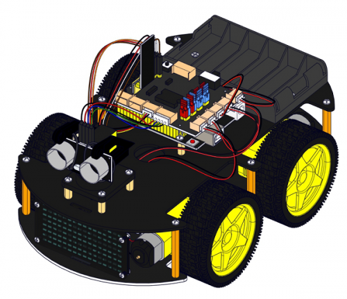
KS0470 Keyestudio 4WD BT Robot Car V2.0 Kit for Mixly
Note:Dear customers, this KS0470 kit was updated on 10th September,2020. The control board was replaced with keyestudio V4.0 board and we also added a red LED module and 3 pcs 3pin female-female jumper wires. The kit can be still used normally even without these two items
Thanks for your support on our products, we will continue to provide you better quality and service!
- About keyestudio
Keyestudio is a best-selling brand owned by KEYES Corporation, our product lines range from controller boards, shields and sensor modules to smart car and complete starter kits for Arduino, Raspberry Pi and BBC micro:bit, which designed for customers of any level to learn electronics and programming knowledge. All of our products comply with international quality standards and are greatly appreciated in a variety of different markets throughout the world.
You can obtain the details and the latest information through visiting the following web sites:http://www.keyestudio.com
- References and After-sales Service
1.Download Profile:https://fs.keyestudio.com/KS0470
2.Feel free to contact us please, if there is missing part or you encounter some troubles. Welcome to send email to us:service@keyestudio.com. We will update projects and products continuously based on your sincere advice.
- Warning
1.This product contains tiny parts(screws, copper pillars), keep it out of reach of children under 7 years old please.
2.This product contains conductive parts (control board and electronic module). Please operate according to the requirements of this tutorial. Improper operation may cause overheating and damage parts. Do not touch and immediately disconnect the circuit power.
- Copyright
The keyestudio trademark and logo are the copyright of KEYES DIY ROBOT co.,LTD. All products under keyestudio brand can’t be copied, sold and resold without authorization by anyone or company. If you’re interested in our items, please contact to our sales representatives: fennie@keyestudio.com
Introduction
Nowadays, technological education such as VR, kids programming, and artificial intelligence, has become mainstream in educational industry. Thereby, people attach importance to STEAM education. Arduino is pretty notable in Maker education.
So what is Arduino? Arduino is an open-source electronics platform based on easy-to-use hardware and software. Arduino boards are able to read inputs - light on a sensor, a finger on a button, or a Twitter message - and turn it into an output - activating a motor, turning on an LED, publishing something online. Based on this, Keyestudio team has designed a 4wd robot. It has a processor which is programmable using the Arduino IDE, to mapped its pins to sensors and actuators by a shield that plug in the processor, it reads sensors and controls the actuators and decides how to operate.
15 learning projects, from simple to complex, will guide you how to make a smart 4wd robot on you own and introduce the detailed knowledge about sensors and modules.
Simultaneously, it is the best choice if you intend to obtain a DIY robot for learning programming, entertainment and competition requirement.
Note: The experiment you did should be in line with wiring diagram, including about components and wiring method. For example, we supply power with external power in the hook-up diagram, so you also have to use external power rather than USB cable.
Features
- 1.Multi-purpose function: Obstacle avoidance, follow, IR remote control, Bluetooth control, ultrasonic follow and displayed face emoticons.
- 2. Simple assembly: No soldering circuit required, complete assembly easily.
- 3. High Tenacity: Aluminum alloy bracket, metal motors, high quality wheels and tracks
- 4. High extension: expand other sensors and modules through motor driver shield and sensor shield
- 5. Multiple controls: IR remote control, App control(IOS and Android system)
- 6.Basic programming:C language code of Arduino IDE.
Specification
- Working voltage: 5v
- Input voltage: 7-12V
- Maximum output current: 2A
- Maximum power dissipation: 25W (T=75℃)
- Motor speed: 5V 200 rpm/min
- Motor drive mode: dual H bridge drive
- Ultrasonic induction angle: <15 degrees
- Ultrasonic detection distance: 2cm-400cm
- Infrared remote control distance: 10 meters (measured)
- Bluetooth remote control distance: 50 meters (measured)
- Bluetooth control: support Android and iOS system
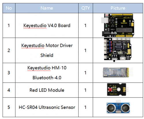
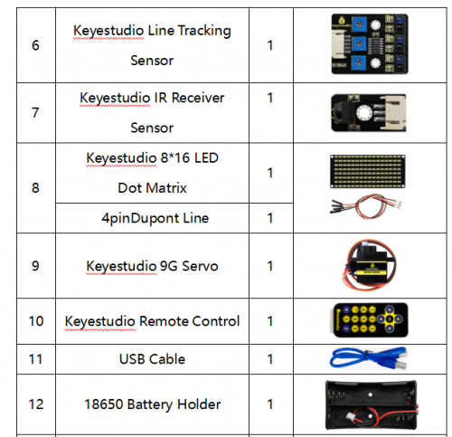
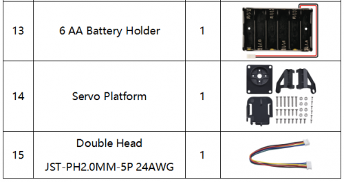
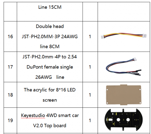
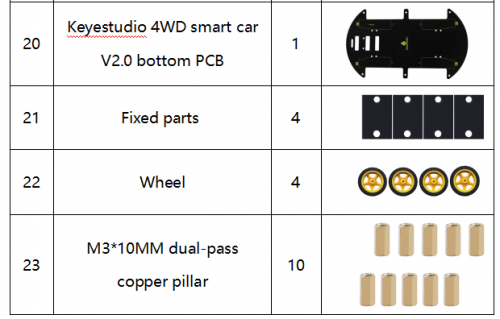
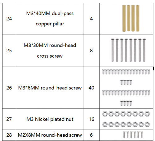
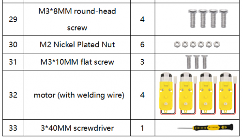
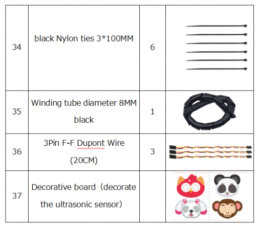
Product List
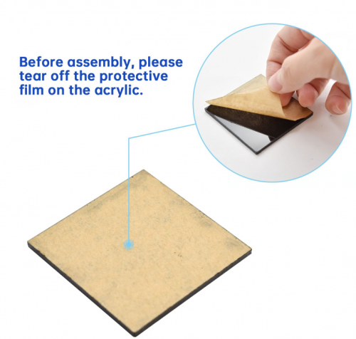
Please tear off the protective film on the acrylic board before mounting the kit
Assembly Guide
Note: Peel the plastic film off the board first when installing the smart car. To be honest, we never intend to send wood to you.
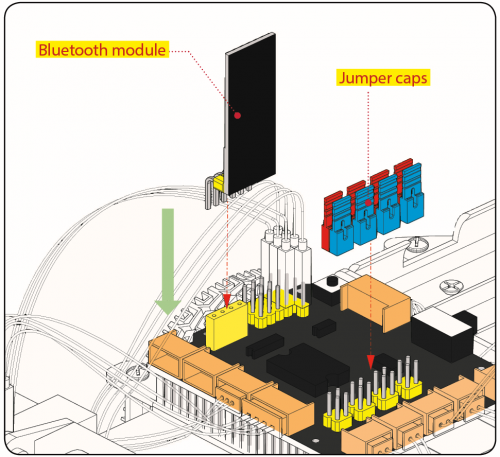
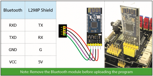
Note: Remove the Bluetooth module before uploading test code, otherwise, you will fail to upload test code
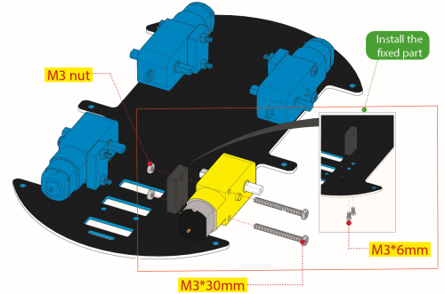
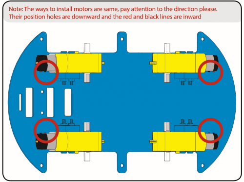
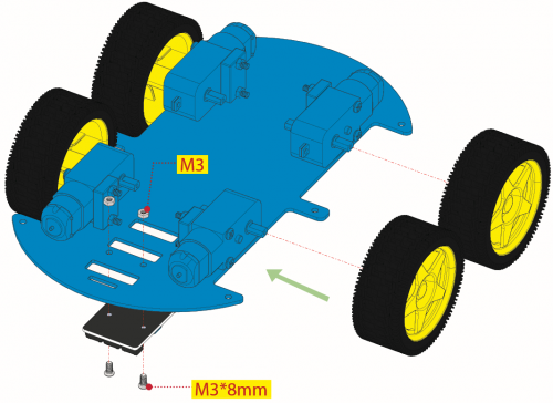
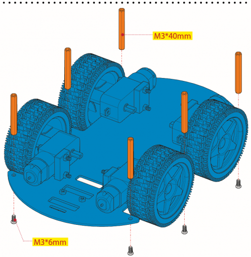
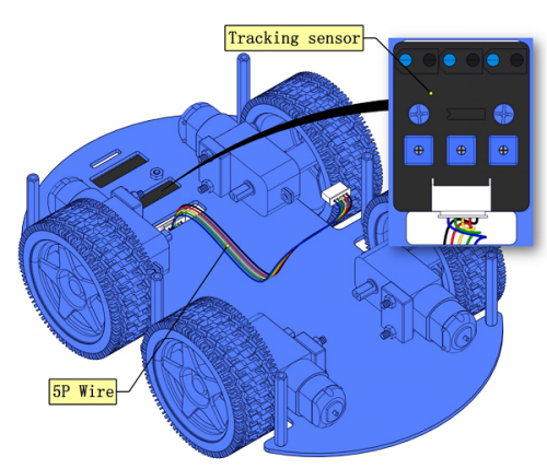
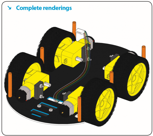
Step 1:Mount the Bottom PCB Prepare the parts as follows:
- Gear motor *4
- Fixed part *4
- M3 nickel plated nut *10
- M3*6mm round-head screw *14
- 4WD bottom PCB *1
- Tracking sensor *1
- Wheel *4
- Dual 5p wire *1
- M3*40mm copper pillar*6
- M3*30m round-head screw *8
- M3*8mm round-head screw *2
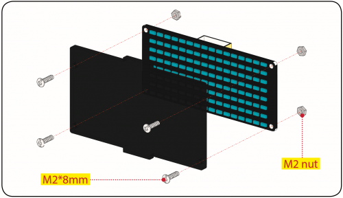
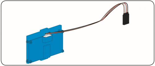
Step 2: Install Dot Matrix
Prepare the parts as follows:
- 8*16 LED panel *1
- 4Wd baffle
- 4P wire *1
- M2x8mm round-head screw *4
- M2 nut *4
Step 3: Servo plastic platform
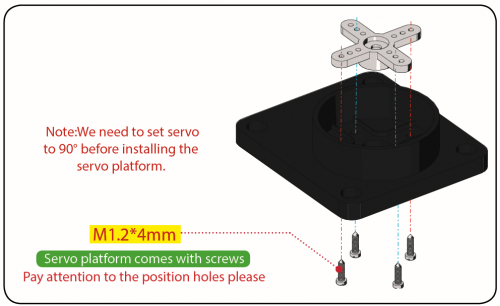
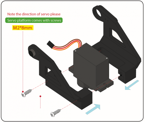
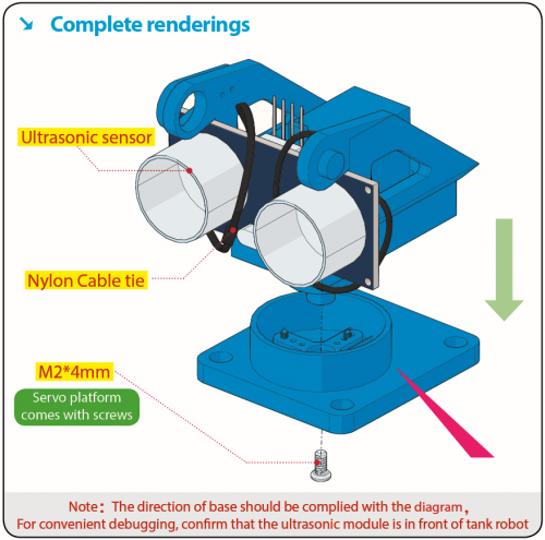
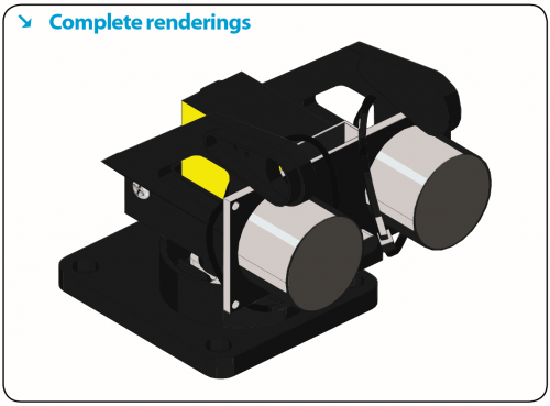
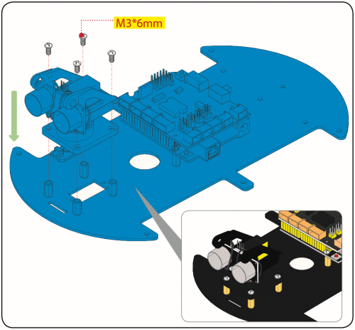
Prepare the parts as follows: Servo *1 M2*4 screw *1 Black cable tie*2 Ultrasonic sensor*1 Black servo platform *1 M1.2*4 tapping screw *4 M2*8 tapping screw *2
Step 4: Install the Top PCB
Prepare the parts as follows:
- Top PCB *1
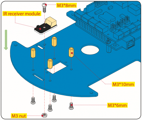
- M3 nut *3
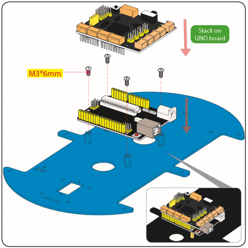
- Motor drive board *1
- Control board *1
- IR receiver module *1
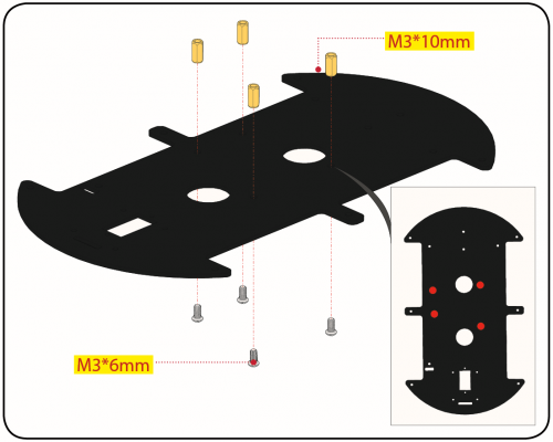
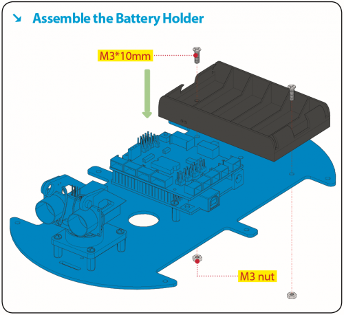
- M3*10mm copper pillar *8
- M3*8mm round-head screw *1
- M3*6mm round-head screw *16
- M3*10mm flat screw *2
- 6-Cell AA battery holder *1
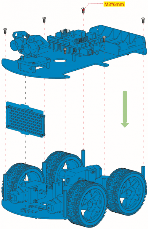
Step 5: Install Top PCB
Prepare the parts as follows:
- Bluetooth module *1
- M3*6MM round-head screw *6
- Jumper cap *8
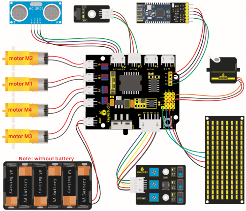
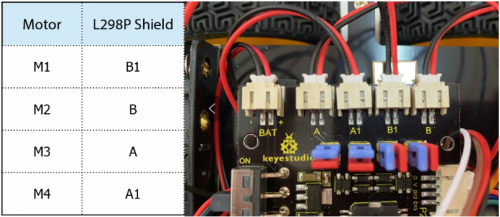
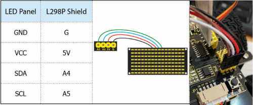
Step 6: Hook-up Guide
Install Mixly Software and Driver
(1)Download and Install Mixly
①Description
Mixly is a free open-source graphical Arduino programming software, based on Google’s Blockly graphical programming framework, and developed by Mixly Team@ BNU.
It is a complete support ecosystem for creative e-education, a stage for maker educators to realize their dreams.
② Download Mixly1.0
Windows System:https://fs.keyestudio.com/Mixly1-Windows
MACOS System:https://fs.keyestudio.com/Mixly1-MACOS
We will take Mixly1.0 (Windows version) as example, and the installation method of MAC version is similar with it.
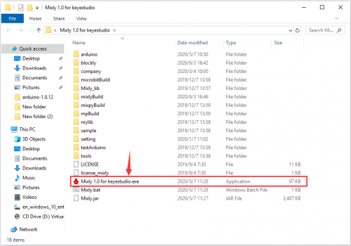
You will get installation package after downloading. As shown below:
Unzip the package, you will see “Mixly 1.0 for keyestudio.exe”
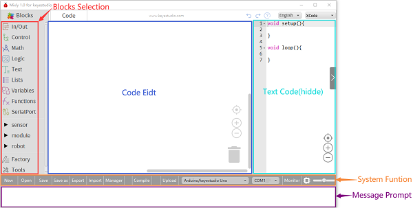
Double-click ![]() ”Mixly 1.0 for keyestudio.exe”, the following interface pops up.
”Mixly 1.0 for keyestudio.exe”, the following interface pops up.
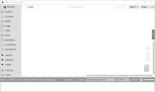
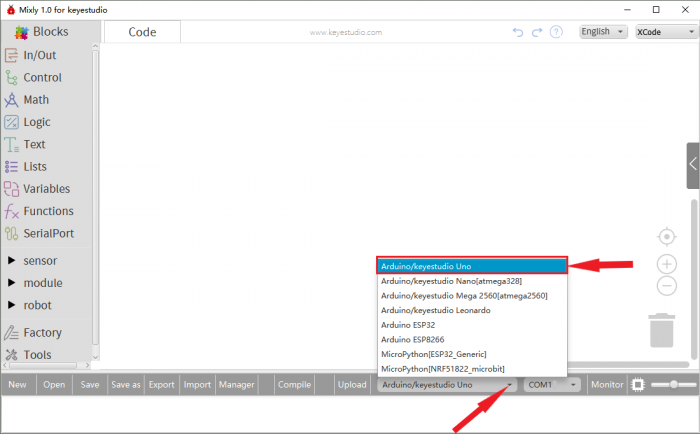
We have to choose correct Arduino development board and name, as shown below:
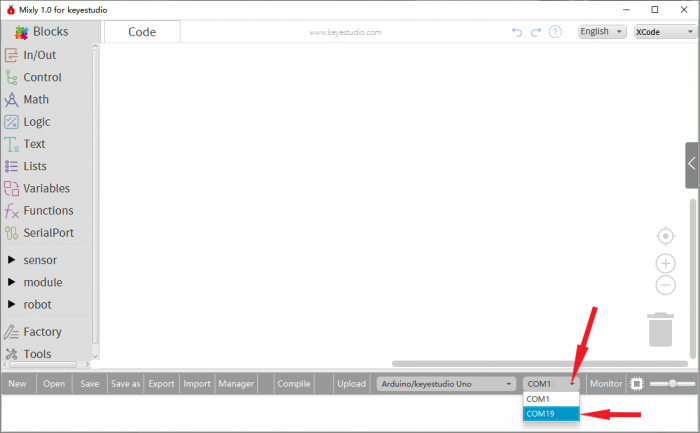
Select correct COM port(the corresponding port will be shown after installing driver successfully)
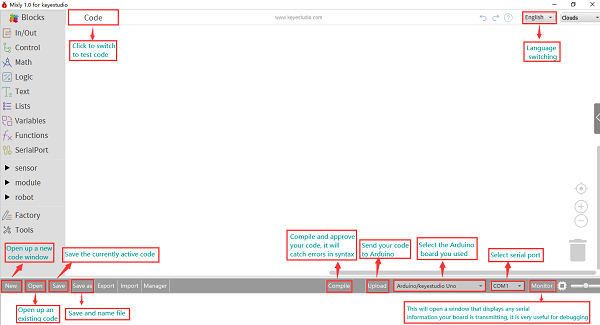
You have to know the function of every area and interface on Mixly software before uploading program on Arduino development board
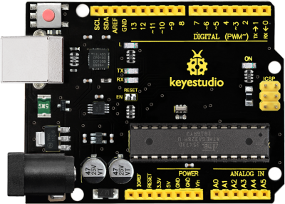
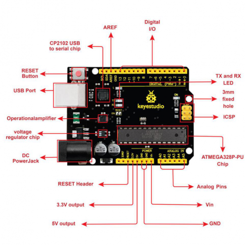
Keyestudio V4.0 Development Board
We need to know keyestudio V4.0 development board, as a core of this smart car.
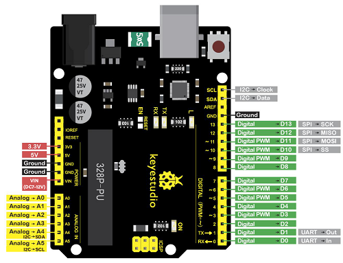
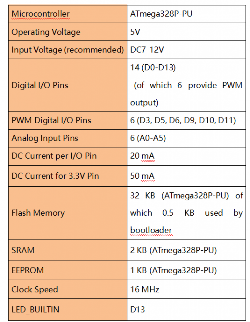
keyestudio V4.0 development board is an Arduino uno-compatible board, which is based on ATmega328P MCU, and with a cp2102 Chip as a UART-to-USB converter.
It has 14 digital input/output pins (of which 6 can be used as PWM outputs), 6 analog inputs, a 16 MHz quartz crystal, a USB connection, a power jack, 2 ICSP headers and a reset button.
It contains everything needed to support the microcontroller; simply connect it to a computer with a USB cable or power it via an external DC power jack (DC 7-12V) or via female headers Vin/ GND(DC 7-12V) to get started.
Installing V4.0 board Driver
Let’s install the driver of keyestudio V4.0 board. The USB-TTL chip on V4.0 board adopts CP2102 serial chip. The driver program of this chip is included in Arduino 1.8 version and above, which is convenient. Plug on USB port of board, the computer can recognize the hardware and automatically install the driver of CP2102.
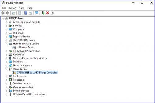
If install unsuccessfully, or you intend to install manually, open the device manager of computer. Right click Computer----- Properties----- Device Manager
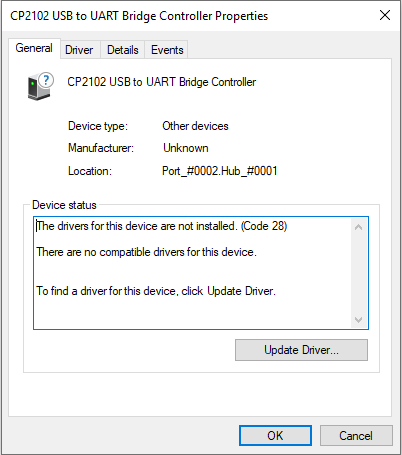
There is a yellow exclamation mark on the page, which implies installing unsuccessfully. Then we double click the hardware and update the driver.
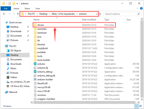
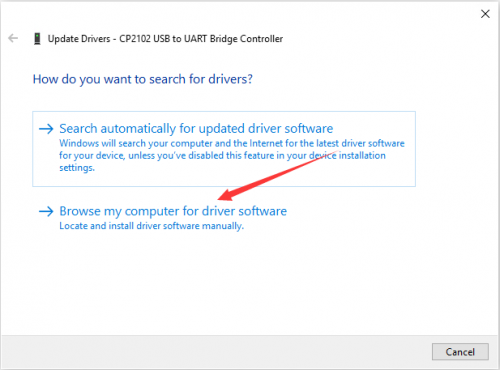
Click “OK” to enter the following page, click “browse my computer for updated driver software”, find out the installed or downloaded ARDUINO software. As shown below:
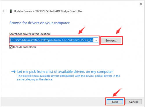
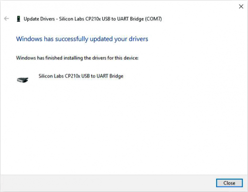
We click “Browse”, then find out the driver folder, or you could enter “driver” to search in rectangular box, then click “next”, the driver will be installed successfully. (I place Arduino software folder on the desktop, you could follow my way)
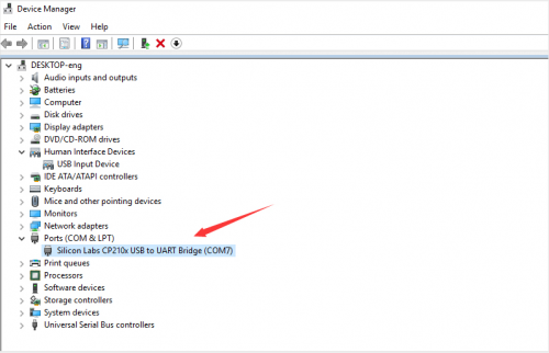
Open device manager, we will find the yellow exclamation mark disappear. The driver of CP2102 is installed successfully.
Start the first program
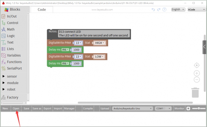
Click“Open”→ sample → arduino→ Arduino → 01 IN-OUT→01-LED Blink.mix
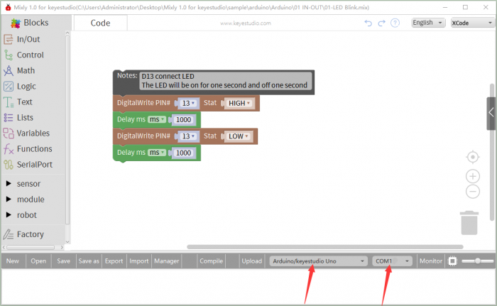
The corresponding board and COM port will be shown after setting board and COM port.
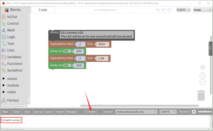
Click Compile to start compiling the program, check errors.
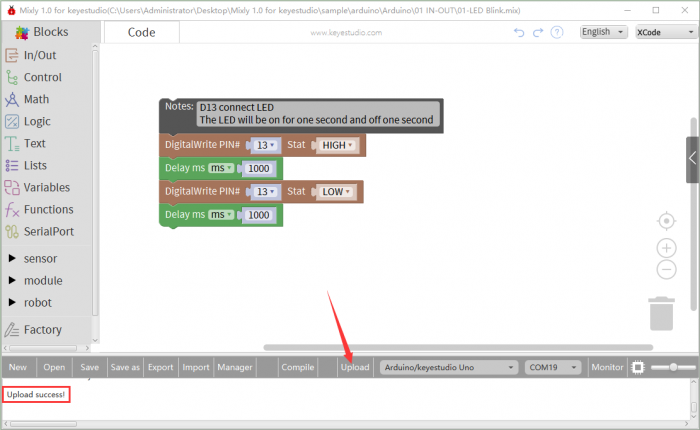
Click Upload to upload the program, upload successfully.
After uploading the program successfully, the on-board LED blinks for 1s. Congratulation, you finish the first program.
Projects:
More detailed projects, please navigate https://fs.keyestudio.com/KS0470
