KS4031(4032)Keyestudio 4WD Mecanum Robot Car for Micro:bit
Introduction:
Have you wondered to learn programming or have your own programming robot? Nowadays, programming has developed to a lower age group, and it will be a trend for everyone to be able to program thanks to the spread of simple graphical programming platforms, from micro:bit to Arduino and Raspberry Pi. Maybe you haven't heard of them before. It doesn't matter because with the help of this product and tutorial, you can easily install a multi-functional programming car and experience the fun of being a maker.
Micro:bit is a highly integrated microcontroller of powerful functions and small size. It is very suitable to be applied in STEAM education for it functions to make robots, wearable devices and electronic interactive games via the combination of code programming and graphical programming.
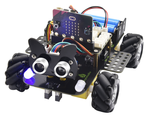
This Keyestudio 4WD Mecanum Robot Car is a smart DIY car specially designed for micro:bit. The smart car kit consists of a car body with extended functions, a PCB base plate with integrated motor drive sensors, 4 decelerating DC motors, Mecanum wheels, various modules and sensors and acrylic boards. Therefore, you can easily assemble a cool Mecanum wheel 4WD smart car by yourself, and then use Microsoft's online graphical programming platform Make Code to program the micro:bit control board to control the car. In the process, you can not only experience the fun of creation but enhance hands-on ability and learn programming skills as well.
MakeCode for micro:bit is the most widely used graphical programming environment on the micro:bit official website. It is based on the graphical programming environment developed by Microsoft's open source project MakeCode. This graphical programming can also be converted to code languages, python and javascript language. This combination makes learn programming easy. At the same time, MakeCode programming can be simulated or programmed for actual electronic components.
For your convenience, source code has been provided in every project, as well as code programming steps and code explanation in details. Hope you can better understand them.
Description:
This product is a smart car based on Micro:bit. It boasts multiply functions including ultrasonic sound following, line tracking, infrared control and Bluetooth control. It comes with a passive buzzer which is able to play music, 4 WS2812RGB LEDs to display different colors, 2 colorful lights to make direction lights for the car. This product uses two 18650 lithium batteries for power supply.
When installing and disassembling the battery, please pay attention to the positive and negative poles of the battery, and be sure not to reverse the them. By the way, the motor speed of this product is adjustable.
In order to provide you with better experience, corresponding documents about installation and test code are also provided.
Parameters:
Connector port input: DC 6V---9V
Operating voltage of drive board system: 5V
Standard operating power consumption: about 2.2W
Maximum power: Maximum output power is 12W
Motor speed: 200RPM/1min
Working temperature range: 0-50℃
Size: 120*120*120mm
Environmental protection attributes: ROHS
Note: working voltage of micro:bit is 3.3V, driver shield integrates 3.3V/5V communication conversion circuit.
Kit List:
Preparations:
5.1 Background Information about Micro:bit
(1) What is Micro:bit?
Micro:bit is an open source hardware platform based on the ARM architecture launched by British Broadcasting Corporation (BBC) together with ARM, Barclays, element14, Microsoft and other institutions. The core device is a 32-bit Arm Cortex-M4 with FPU micro-processing.
Though it is just the size of a credit card, the Micro:bit main board is equipped with loads of components,including a 5*5 LED dot matrix, 2 programmable buttons, an accelerometer, a compass, a thermometer, a touch-sensitive logo and a MEMS microphone, a Bluetooth module of low energy, and a buzzer and others. Thus, it also boasts multiple functions.
The buzzer built in the other side of the board makes playing all kinds of sound possible without any external equipment. The golden fingers and gears added provide a better fixing of crocodile clips. Moreover, this board has a sleeping mode to lower power consumption of batteries and it can be entered if users long press the Reset & Power button on the back of it. It is capable of reading the data of sensors, controlling servos and RGB lights and attaching with a shield so as to connect with various sensors. It also supports a variety of codes and graphical programming platforms, and is compatible with almost all PCs and mobile devices. It has no need to install drivers. It is of high integration of electronic modules, and has a serial port monitoring function for easy debugging.
The board has found wide applications. It can be applied in programming video games, making interactions between light and sound, controlling a robot, conducting scientific experiments, developing wearable devices and make some cool inventions like robots and musical instruments, basically everything imaginable.
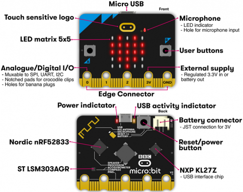
(2) Layout
For more information,please resort to following links:
https://tech.microbit.org/hardware/
https://microbit.org/new-microbit/
https://www.microbit.org/get-started/user-guide/overview/
https://microbit.org/get-started/user-guide/features-in-depth/
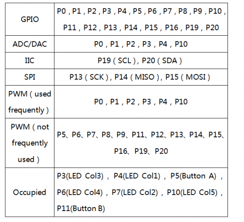
(3) Pinout
The functions of pins:
Browse the official website for more details: https://tech.microbit.org/hardware/edgeconnector/ https://microbit.org/guide/hardware/pins/
(4) Notes for the application of Micro:bit main board
a. It is recommended to cover it with a silicone protector to prevent short circuit for it has a lot of sophisticated electronic components.
b. Its IO port is very weak in driving since it can merely handle current less than 300mA. Therefore, do not connect it with devices operating in large current, such as servo MG995 and DC motor or it will get burnt. Furthermore, you must figure out the current requirements of the devices before you use them and it is generally recommended to use the board together with a Micro:bit shield.
c. It is recommended to power the main board via the USB interface or via the battery of 3V. The IO port of this board is 3V, so it does not support sensors of 5V. If you need to connect sensors of 5 V, a Micro: Bit expansion board is required.
d. When using pins(P3, P4, P6, P7 and P10)shared with the LED dot matrix, blocking them from the matrix or the LEDs may display randomly and the data about sensors connected maybe wrong.
e. Pin 19 and 20 can not be used as IO ports though the Makecode shows they can. They can only be used as I2C communication.
f. The battery port of 3V cannot be connected with battery more than 3.3V or the main board will be damaged.
g. Forbid to operate it on metal products to avoid short circuit.
To put it simple, Micro:bit V2 main board is like a microcomputer which has made programming at our fingertips and enhanced digital innovation. And as for programming environment, BBC provides a website: https://microbit.org/code/, which has a graphical MakeCode program easy for use.
Resources:
Download PDF files: https://fs.keyestudio.com/KS4031-4032


