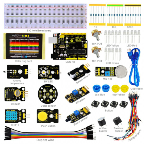
Ks0180 keyestudio Sensor Kit for ARDUINO starters- K3
keyestudio Sensor Kit for ARDUINO starters- K3
Introduction
This keyestudio Sensor Kit is an Arduino stater learning kit developed by Keyes. We provide detailed tutorials for each project or sensor module, including connection diagrams and sample codes, with which you will find it easy for you to complete every experiments. Besides, you can also find video tutorials of this kit on our official website.
Component List
Project details
Project 1: Hello World
Introduction
As for starters, we will begin with something simple. In this project, you only need an Arduino and a USB cable to start the "Hello World!" experiment. This is a communication test of your Arduino and PC, also a primer project for you to have your first try of the Arduino world!
Hardware required
Arduino board *1
USB cable *1
Sample program
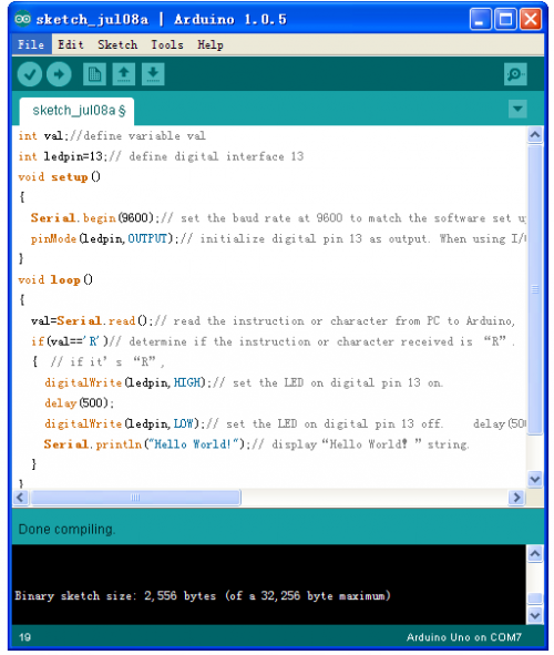
After installing driver for Arduino, let's open Arduino software and compile code that enables Arduino to print "Hello World!" under your instruction. Of course, you can compile code for Arduino to continuously echo "Hello World!" without instruction. A simple If () statement will do the instruction trick. With the onboard LED connected to pin 13, we can instruct the LED to blink first when Arduino gets an instruction and then print "Hello World!”.
int val;//define variable val
int ledpin=13;// define digital interface 13
void setup()
{
  Serial.begin(9600);// set the baud rate at 9600 to match the software set up. When connected to a specific device, (e.g. bluetooth), the baud rate needs to be the same with it.
  pinMode(ledpin,OUTPUT);// initialize digital pin 13 as output. When using I/O ports on an Arduino, this kind of set up is always needed.
}
void loop()
{
  val=Serial.read();// read the instruction or character from PC to Arduino, and assign them to Val.
  if(val=='R')// determine if the instruction or character received is “R”.
  {  // if it’s “R”,
    digitalWrite(ledpin,HIGH);// set the LED on digital pin 13 on.
    delay(500);
digitalWrite(ledpin,LOW);// set the LED on digital pin 13 off.
 delay(500);
    Serial.println("Hello World!");// display“Hello World!”string.
  }
}
Result
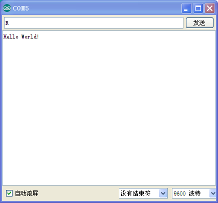
Click serial port monitor,Input R,LED 13 will blink once,PC will receive information from Arduino: Hello World
After you choosing the right port,the experiment should be easy for you!
Project 2: LED blinking
Introduction
Blinking LED experiment is quite simple. In the "Hello World!" program, we have come across LED. This time, we are going to connect an LED to one of the digital pins rather than using LED13, which is soldered to the board. Except an Arduino and an USB cable, we will need extra parts as below:
Hardware required
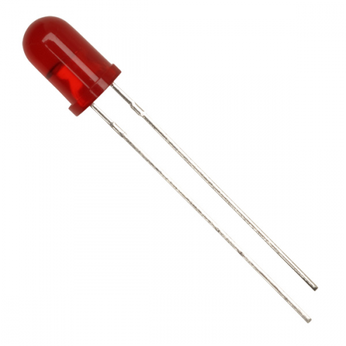
Red M5 LED*1
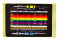
220Ω resistor*1
Breadboard*1
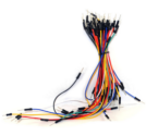
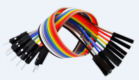
Breadboard jumper wires
Circuit connection
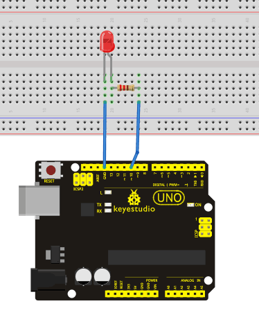
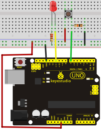
We follow below diagram from the experimental schematic link. Here we use digital pin 10. We connect LED to a 220 ohm resistor to avoid high current damaging the LED.
Sample program
int ledPin = 10; // define digital pin 10.
void setup()
{
pinMode(ledPin, OUTPUT);// define pin with LED connected as output.
}
void loop()
{
digitalWrite(ledPin, HIGH); // set the LED on.
delay(1000); // wait for a second.
digitalWrite(ledPin, LOW); // set the LED off.
delay(1000); // wait for a second
}
Result
After downloading this program, in the experiment, you will see the LED connected to pin 10 turning on and off, with an interval approximately one second. The LED blinking experiment is now complete. Thank you!
Project 3: PWM
Introduction
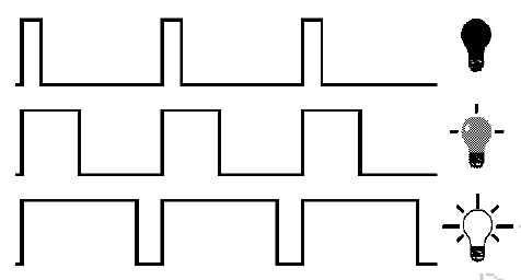
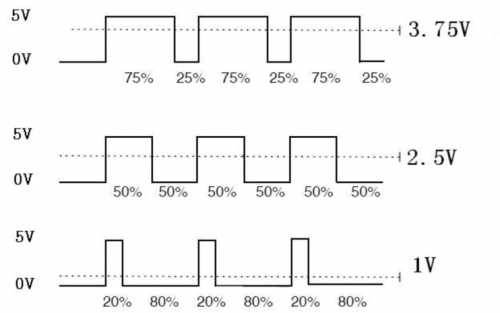
PWM, short for Pulse Width Modulation, is a technique used to encode analog signal level into digital ones. A computer cannot output analog voltage but only digital voltage values such as 0V or 5V. So we use a high resolution counter to encode a specific analog signal level by modulating the duty cycle of PMW. The PWM signal is also digitalized because in any given moment, fully on DC power supply is either 5V (ON), or 0V (OFF). The voltage or current is fed to the analog load (the device that uses the power) by repeated pulse sequence being ON or OFF. Being on, the current is fed to the load; being off, it's not. With adequate bandwidth, any analog value can be encoded using PWM. The output voltage value is calculated via the on and off time. Output voltage = (turn on time/pulse time) * maximum voltage value
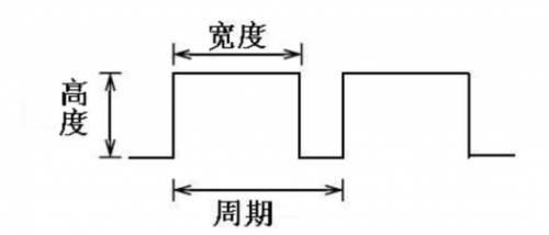
PWM has many applications: lamp brightness regulating, motor speed regulating, sound making, etc. The following are the three basic parameters of PMW:
1. The amplitude of pulse width (minimum / maximum)
2. The pulse period (The reciprocal of pulse frequency in 1 second)
3. The voltage level(such as:0V-5V)
There are 6 PMW interfaces on Arduino, namely digital pin 3, 5, 6, 9, 10, and 11. In previous experiments, we have done "button-controlled LED", using digital signal to control digital pin, also one about potentiometer. This time, we will use a potentiometer to control the brightness of the LED.
Hardware required
Potentiometer module*1
Red M5 LED*1
220Ω resistor
Breadboard*1
Breadboard jumper wires
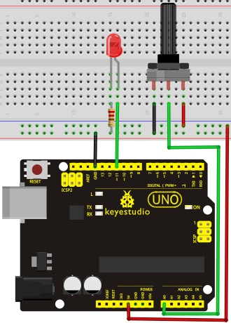
Circuit connection
The input of potentiometer is analog, so we connect it to analog port, and LED to PWM port. Different PWM signal can regulate the brightness of the LED.
Sample program
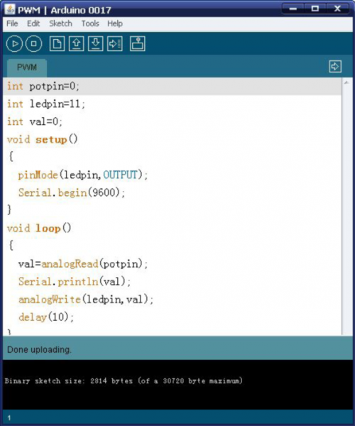
In the program compiling process, we will use the analogWrite (PWM interface, analog value) function. In this experiment, we will read the analog value of the potentiometer and assign the value to PWM port, so there will be corresponding change to the brightness of the LED. One final part will be displaying the analog value on the screen. You can consider this as the "analog value reading" project adding the PWM analog value assigning part. Below is a sample program for your reference.
int potpin=0;// initialize analog pin 0
int ledpin=11;//initialize digital pin 11(PWM output)
int val=0;// Temporarily store variables' value from the sensor
void setup()
{
pinMode(ledpin,OUTPUT);// define digital pin 11 as “output”
Serial.begin(9600);// set baud rate at 9600
// attention: for analog ports, they are automatically set up as “input”
}
void loop()
{
val=analogRead(potpin);// read the analog value from the sensor and assign it to val
Serial.println(val);// display value of val
analogWrite(ledpin,val/4);// turn on LED and set up brightness(maximum output of PWM is 255)
delay(10);// wait for 0.01 second
}
Result
After downloading the program, when we rotate the potentiometer knob, we can see changes of the displaying value, also obvious change of the LED brightness on the breadboard.
Project 4: Traffic light
Introduction
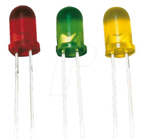
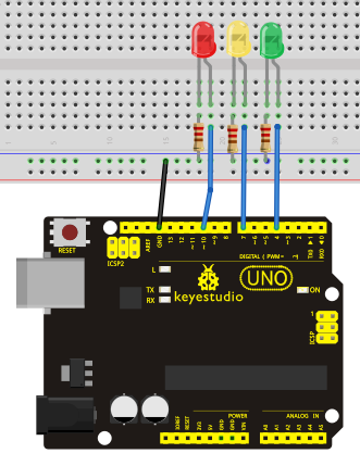
In the previous program, we have done the LED blinking experiment with one LED. Now, it’s time to up the stakes and do a bit more complicated experiment-traffic lights. Actually, these two experiments are similar. While in this traffic lights experiment, we use 3 LEDs with different color other than 1 LED.
Hardware required
Arduino board *1
USB cable *1
Red M5 LED*1
Yellow M5 LED*1
Green M5 LED*1
220Ω resistor *3
Breadboard*1
Breadboard jumper wires
Circuit connection
Sample program
Since it is a simulation of traffic lights, the blinking time of each LED should be the same with those in traffic lights system. In this program, we use Arduino delay () function to control delay time, which is much simpler than C language.
int redled =10; // initialize digital pin 8.
int yellowled =7; // initialize digital pin 7.
int greenled =4; // initialize digital pin 4.
void setup()
{
pinMode(redled, OUTPUT);// set the pin with red LED as “output”
pinMode(yellowled, OUTPUT); // set the pin with yellow LED as “output”
pinMode(greenled, OUTPUT); // set the pin with green LED as “output”
}
void loop()
{
digitalWrite(greenled, HIGH);//// turn on green LED
delay(5000);// wait 5 seconds
digitalWrite(greenled, LOW); // turn off green LED
for(int i=0;i<3;i++)// blinks for 3 times
{
delay(500);// wait 0.5 second
digitalWrite(yellowled, HIGH);// turn on yellow LED
delay(500);// wait 0.5 second
digitalWrite(yellowled, LOW);// turn off yellow LED
}
delay(500);// wait 0.5 second
digitalWrite(redled, HIGH);// turn on red LED
delay(5000);// wait 5 second
digitalWrite(redled, LOW);// turn off red LED
}
Result
When the uploading process is completed, we can see traffic lights of our own design.
Note: this circuit design is very similar with the one in LED chase effect. The green light will be on for 5 seconds, and then off., followed by the yellow light blinking for 3 times, and then the red light on for 5 seconds, forming a cycle. Cycle then repeats. Experiment is now completed, thank you.
Project 5: LED chasing effect
Introduction
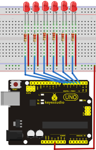
We often see billboards composed of colorful LEDs. They are constantly changing to form various effects. In this experiment, we compile a program to simulate chase effect.
Hardware required
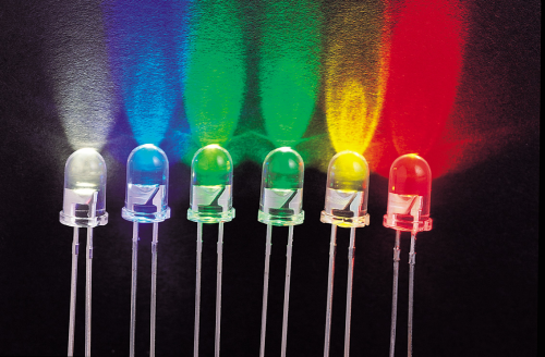
Led *6
220Ω resistor *6
Breadboard jumper wires
Circuit connection
Sample program
int BASE = 2 ;  // the I/O pin for the first LED
int NUM = 6;   // number of LEDs

void setup()
{
   for (int i = BASE; i < BASE + NUM; i ++)
   {
     pinMode(i, OUTPUT);   // set I/O pins as output
   }
}

void loop()
{
   for (int i = BASE; i < BASE + NUM; i ++)
   {
     digitalWrite(i, LOW);    // set I/O pins as “low”, turn off LEDs one by one.
     delay(200);        // delay
   }
   for (int i = BASE; i < BASE + NUM; i ++)
   {
     digitalWrite(i, HIGH);    // set I/O pins as “high”, turn on LEDs one by one
     delay(200);        // delay
   }
}
Result You can see the LEDs blink by sequence.
Project 6: Button-controlled LED
Introduction
I/O port means interface for INPUT and OUTPUT. Up until now, we have only used its OUTPUT function. In this experiment, we will try to use the input function, which is to read the output value of device connecting to it. We use 1 button and 1 LED using both input and output to give you a better understanding of the I/O function. Button switches, familiar to most of us, are a switch value (digital value) component. When it's pressed, the circuit is in closed (conducting) state.
Hardware required
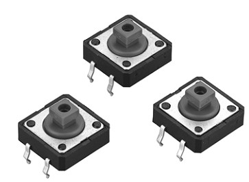
Button switch*1
Red M5 LED*1
220Ω resistor*1
10KΩ resistor*1
Breadboard*1
Breadboard jumper wires
Circuit connection
Sample program
Now, let's begin the compiling. When the button is pressed, the LED will be on. After the previous study, the coding should be easy for you. In this program, we add a statement of judgment. Here, we use an if () statement. Arduino IDE is based on C language, so statements of C language such as while, switch etc. can certainly be used for Arduino program. When we press the button, pin 7 will output high level. We can program pin 11 to output high level and turn on the LED. When pin 7 outputs low level, pin 11 also outputs low level and the LED remains off.
int ledpin=11;// initialize pin 11
int inpin=7;// initialize pin 7
int val;// define val
void setup()
{
pinMode(ledpin,OUTPUT);// set LED pin as “output”
pinMode(inpin,INPUT);// set button pin as “input”
}
void loop()
{
val=digitalRead(inpin);// read the level value of pin 7 and assign if to val
if(val==LOW)// check if the button is pressed, if yes, turn on the LED
{ digitalWrite(ledpin,LOW);}
else
{ digitalWrite(ledpin,HIGH);}
}
Result
When the button is pressed, LED is on, otherwise, LED remains off. After the above process, the button controlled LED experiment is completed. The simple principle of this experiment is widely used in a variety of circuit and electric appliances. You can easily come across it in your every day life. One typical example is when you press a certain key of your phone, the backlight will be on.
Project 7: Responder experiment
Introduction
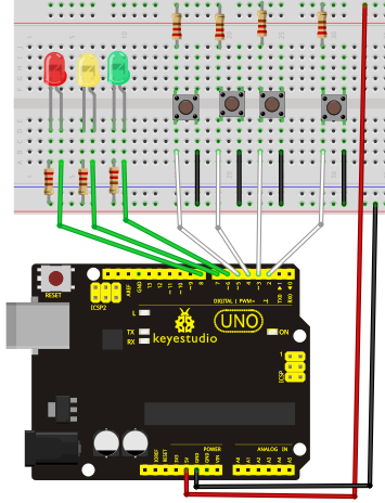
After completing all the previous experiments, we believe you will find this one easy. In this program, we have 3 buttons and a reset button controlling the corresponding 3 LEDs, using 7 digital I/O pins.
Hardware required
Button switch*4
Red M5 LED*1
Yellow M5 LED*1
Green M5 LED*1
220Ω resistor*3
10KΩ resistor*4
Breadboard*1
Breadboard jumper wires
Circuit connection
Sample program
int redled=8;     // set red LED as “output”
int yellowled=7;  // set yellow LED as “output”
int greenled=6;   // set green LED as “output”
int redpin=5;     // initialize pin for red button
int yellowpin=4;  // initialize pin for yellow button
int greenpin=3;   // initialize pin for green button
int restpin=2;   // initialize pin for reset button
int red;
int yellow;
int green;
void setup()
{
pinMode(redled,OUTPUT);
pinMode(yellowled,OUTPUT);
pinMode(greenled,OUTPUT);
pinMode(redpin,INPUT);
pinMode(yellowpin,INPUT);
pinMode(greenpin,INPUT);
}
void loop()  // repeatedly read pins for buttons
{
red=digitalRead(redpin);
yellow=digitalRead(yellowpin);
green=digitalRead(greenpin);
if(red==LOW)RED_YES();
if(yellow==LOW)YELLOW_YES();
if(green==LOW)GREEN_YES();
}

void RED_YES()// execute the code until red light is on; end cycle when reset button is pressed
{
  while(digitalRead(restpin)==1)
  {
   digitalWrite(redled,HIGH);
   digitalWrite(greenled,LOW);
   digitalWrite(yellowled,LOW);
  }
  clear_led();
}
void YELLOW_YES()// execute the code until yellow light is on; end cycle when reset button is pressed
{
  while(digitalRead(restpin)==1)
  {
  digitalWrite(redled,LOW);
  digitalWrite(greenled,LOW);
  digitalWrite(yellowled,HIGH);
  }
  clear_led();
}
void GREEN_YES()// execute the code until green light is on; end cycle when reset button is pressed
{
  while(digitalRead(restpin)==1)
  {
  digitalWrite(redled,LOW);
  digitalWrite(greenled,HIGH);
  digitalWrite(yellowled,LOW);
  }
  clear_led();
}
void clear_led()// all LED off
{
  digitalWrite(redled,LOW);
  digitalWrite(greenled,LOW);
  digitalWrite(yellowled,LOW);
}
Result
Whichever button is pressed first, the corresponding LED will be on! Then press the REST button to reset. After the above process, we have built our own simple responder.
Project 8: Active buzzer
Introduction
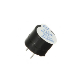
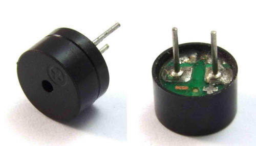
Arduino enables us to make many interesting interactive projects, many of which we have done consists of a LED. They are light-related. While this time, the circuit will produce sound. The sound experiment is usually done with a buzzer or a speaker, while buzzer is simpler and easier to use. The buzzer we introduced here is a passive buzzer. It cannot be actuated by itself, but by external pulse frequencies. Different frequencies produce different sounds. We can use Arduino to code the melody of a song, which is actually fun and simple.
Hardware required
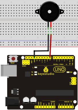
Buzzer*1
Key *1
Breadboard*1
Breadboard jumper wires
Circuit connection
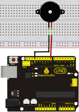
When connecting the circuit, pay attention to the positive & the negative poles of the buzzer. In the photo, you can see there are red and black lines. When the circuit is finished, you can begin programming.
Sample program
Program is simple. You control the buzzer by outputting high/low level.
int buzzer=8;// initialize digital IO pin that controls the buzzer
void setup()
{
  pinMode(buzzer,OUTPUT);// set pin mode as “output”
}
void loop()
{
digitalWrite(buzzer, HIGH); // produce sound
}
Result
After downloading the program, the buzzer experiment is completed. You can see the buzzer is ringing.
Project 9: Passive buzzer
Introduction
We can use Arduino to make many interactive works of which the most commonly used is acoustic-optic display. All the previous experiment has something to do with LED. However, the circuit in this experiment can produce sound. Normally, the experiment is done with a buzzer or a speaker while buzzer is simpler and easier to use. The buzzer we introduced here is a passive buzzer. It cannot be actuated by itself, but by external pulse frequencies. Different frequencies produce different sounds. We can use Arduino to code the melody of a song, which is actually quite fun and simple.
Hardware required
Passive buzzer*1
Key *1
Breadboard*1
Breadboard jumper wires
Sample program
int buzzer=8;// select digital IO pin for the buzzer
void setup()
{
pinMode(buzzer,OUTPUT);// set digital IO pin pattern, OUTPUT to be output
}
void loop()
{ unsigned char i,j;//define variable
while(1)
{ for(i=0;i<80;i++)// output a frequency sound
{ digitalWrite(buzzer,HIGH);// sound
delay(1);//delay1ms
digitalWrite(buzzer,LOW);//not sound
delay(1);//ms delay
}
for(i=0;i<100;i++)// output a frequency sound
{ digitalWrite(buzzer,HIGH);// sound
digitalWrite(buzzer,LOW);//not sound
delay(2);//2ms delay
}
}
}
After downloading the program, buzzer experiment is finished.
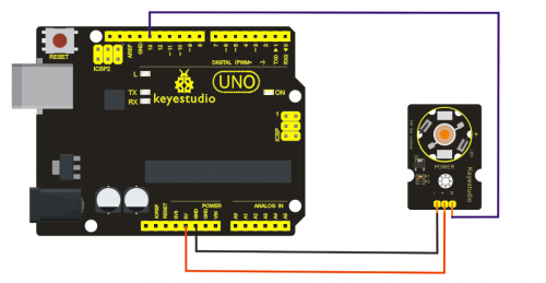
Project 10: 3W LED Module
Introduction
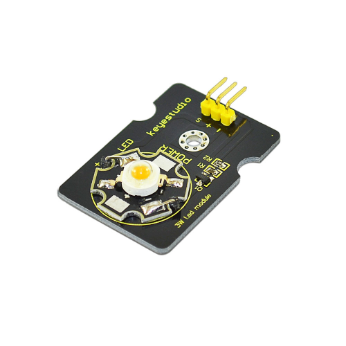
This LED module is of high brightness because the lamp beads it carries is 3w. We can apply this module to Arduino projects. For example, intelligent robots can use this module for illumination purpose.
Please note that the LED light can't be exposed directly to human eyes for safety concerns.
Specification
Color temperature: 6000~7000K
Luminous flux: 180~210lm
Current: 700~750mA
Power: 3W
Light angle: 140 degree
Working temperature: -50~80'C
Storage temperature: -50~100'C
High power LED module, controlled by IO port microcontroller
Great for Robot and search & rescue platform application
IO Type: Digital
Supply Voltage: 3.3V to 5V
Size: 40x28mm
Weight: 6g
Connection Diagram
Sample Code
// the setup function runs once when you press reset or power the board
void setup() {
  // initialize digital pin 13 as an output.
  pinMode(13, OUTPUT);
}

// the loop function runs over and over again forever
void loop() {
  digitalWrite(13, HIGH);   // turn the LED on (HIGH is the voltage level)
  delay(1000);              // wait for a second
  digitalWrite(13, LOW);    // turn the LED off by making the voltage LOW
  delay(1000);              // wait for a second
}
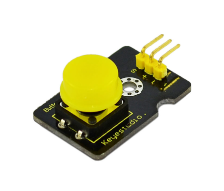
Project 11: Digital Push Button
Introduction
This is a basic application module. You can simply plug it into an IO shield to have your first taste of Arduino.
Advantages
Wide voltage range from 3.3V to 5V
Standard assembling structure (two 3mm diameter holes with multiple of 5mm as distance from center)
Easily recognizable interfaces of sensors ("A" for analog and "D" for digital)
Icons illustrate sensor function clearly
High quality connector
Immersion gold surface
Specification
Supply Voltage: 3.3V to 5V
Easy to 'plug and operate'
Large button keypad and high-quality first-class cap
Achieve interesting and interactive work
Interface: Digital
Size: 30*20mm
Weight: 4g
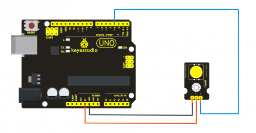
Connection diagram
Sample Code
/* # When you push the digital button, the Led 13 on the board will turn on. Otherwise,the led turns off.
*/
int ledPin = 13;                // choose the pin for the LED
int inputPin = 3;               // Connect sensor to input pin 3
void setup() {
  pinMode(ledPin, OUTPUT);      // declare LED as output
  pinMode(inputPin, INPUT);     // declare pushbutton as input
}
void loop(){
  int val = digitalRead(inputPin);  // read input value
  if (val == HIGH) {            // check if the input is HIGH
    digitalWrite(ledPin, LOW);  // turn LED OFF
  } else {
    digitalWrite(ledPin, HIGH); // turn LED ON
  }
}
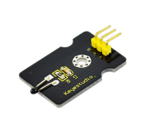
Project 12: Analog temperature sensor
Introduction
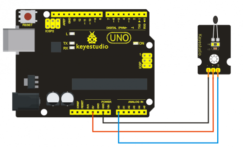
This module is based on the working principle of a thermistor (resistance varies with temperature change in the environment). It can sense temperature change in its surrounding and send the data to the analog IO in the Arduino board. All we need to do is to convert the sensor output data to degrees Celsius temperature by simple programming and display it. It's both convenient and effective, and it’s widely applied in gardening, home alarm system and other devices.
Specification
Interface type: analog
Working voltage: 5V
Temperature range: -55℃~315℃
Size: 30*20mm
Weight: 3g
Connection Diagram
Sample Code
void setup()
{Serial.begin(9600);
}
// the loop routine runs over and over again forever:
void loop()
{int sensorValue = analogRead(A0);
Serial.println(sensorValue);
  delay(1); }
We can see that the analog value is changing according to the temperature change in the environment. But it’s not very obvious. Let’s solve this by using the following equation. The value read from the serial port is similar to normal temperature, eg. The temperature right now is 30C.
#include <math.h>
double Thermister(int RawADC) {
double Temp;
Temp = log(((10240000/RawADC) - 10000));
Temp = 1 / (0.001129148 + (0.000234125 + (0.0000000876741 * Temp * Temp ))* Temp );
Temp = Temp - 273.15; // Convert Kelvin to Celcius
return Temp;
}
void setup()
{Serial.begin(9600);
} void loop() { Serial.print(Thermister(analogRead(0))); // display Fahrenheit Serial.println("c"); delay(500);
}
Project 13: DHT11 Temperature and Humidity Sensor
Introduction
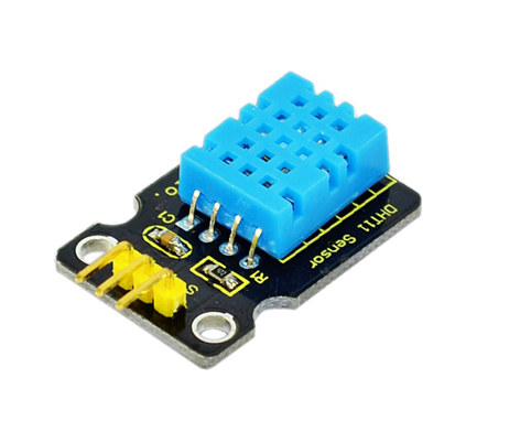
This DHT11 Temperature and Humidity Sensor features calibrated digital signal output with the temperature and humidity sensor complex. Its technology ensures high reliability and excellent long-term stability. A high-performance 8-bit microcontroller is connected. This sensor includes a resistive element and a sense of wet NTC temperature measuring devices. It has excellent quality, fast response, anti-interference ability and high cost performance advantages. Each DHT11 sensor features extremely accurate calibration data of humidity calibration chamber. The calibration coefficients stored in the OTP program memory, internal sensors detect signals in the process, and we should call these calibration coefficients. The single-wire serial interface system is integrated to make it quick and easy. Qualities of small size, low power, and 20-meter signal transmission distance make it a wide applied application and even the most demanding one. Convenient connection, special packages can be provided according to users need.
Specification
Supply Voltage: +5 V
Temperature range: 0-50 °C error of ± 2 °C
Humidity: 20-90% RH ± 5% RH error
Interface: Digital
Size: 30*20mm
Weight: 4g
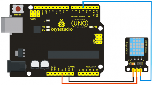
Connection diagram
Sample Code
Please download the DHT11Lib firstly.Or,see the website.
#include <dht11.h>
dht11 DHT;
#define DHT11_PIN 4

void setup(){
  Serial.begin(9600);
  Serial.println("DHT TEST PROGRAM ");
  Serial.print("LIBRARY VERSION: ");
  Serial.println(DHT11LIB_VERSION);
  Serial.println();
  Serial.println("Type,\tstatus,\tHumidity (%),\tTemperature (C)");
}

void loop(){
  int chk;
  Serial.print("DHT11, \t");
  chk = DHT.read(DHT11_PIN);    // READ DATA
  switch (chk){
    case DHTLIB_OK:
                Serial.print("OK,\t");
                break;

case DHTLIB_ERROR_CHECKSUM:

                Serial.print("Checksum error,\t");
                break;
    case DHTLIB_ERROR_TIMEOUT:
                Serial.print("Time out error,\t");
                break;
    default:
                Serial.print("Unknown error,\t");
                break;
  }
 // DISPLAT DATA
  Serial.print(DHT.humidity,1);
  Serial.print(",\t");
  Serial.println(DHT.temperature,1);

  delay(1000);
}
Project 14: Analog Sound Sensor
Introduction
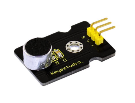
Analog Sound Sensor is typically used in detecting the loudness in ambient environment. The Arduino can collect its output signal by imitating the input interface. You can use it to make some interesting interactive works such as a voice operated switch.
Specification
Supply Voltage: 3.3V to 5V
Detecting sound intensity
Interface: Analog
Size: 30*20mm
Weight: 4g
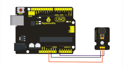
Connection Diagram
Sample Code
void setup()
{
  Serial.begin(9600); // open serial port, set the baud rate at 9600 bps
}
void loop()
{
      int val;
      val=analogRead(0);   //connect mic sensor to Analog 0
      Serial.println(val,DEC);// print the sound value to serial monitor
      delay(100);
}
Project 15: Flame Sensor
Introduction
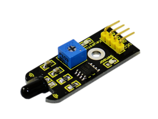
This flame sensor can be used to detect fire or other lights whose wavelength stands at 760 nm ~ 1100 nm. In the fire-fighting robot game, the flame plays an important role in the probe, which can be used as the robot's eyes to find fire source.
Specification
Supply Voltage: 3.3V to 5V
Detection range: 20cm (4.8V) ~ 100cm (1V)
Rang of Spectral Bandwidth: 760nm to 1100nm
Operating temperature: -25℃to 85℃
Interface: digital
Size: 44*16.7mm
Weight: 4g
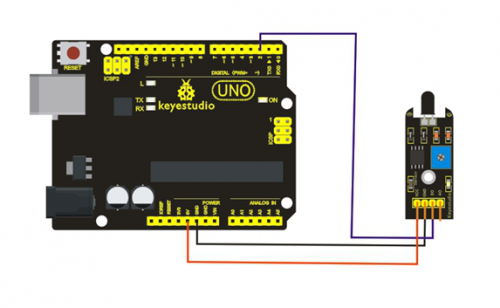
Connection Diagram
Sample Code
const int flamePin = 2;     // the number of the flame pin
const int ledPin =  13;      // the number of the LED pin
// variables will change:
int State = 0;         // variable for reading status
void setup() {
  // initialize the LED pin as an output:
  pinMode(ledPin, OUTPUT);
  // initialize the pushbutton pin as an input:
  pinMode(flamePin, INPUT);
}
void loop(){
  // read the state of the value:
State = digitalRead(flamePin);
  if (State == HIGH) {
    // turn LED on:
    digitalWrite(ledPin, HIGH);
  }
  else {
    // turn LED off:
    digitalWrite(ledPin, LOW);
  }
}
Project 16: Vibration Sensor
Introduction
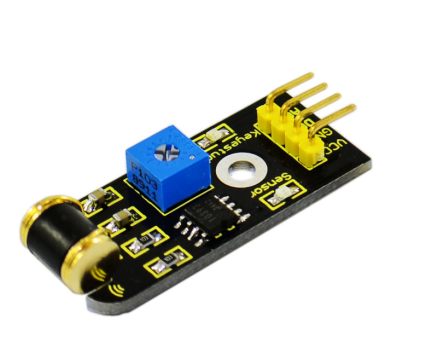
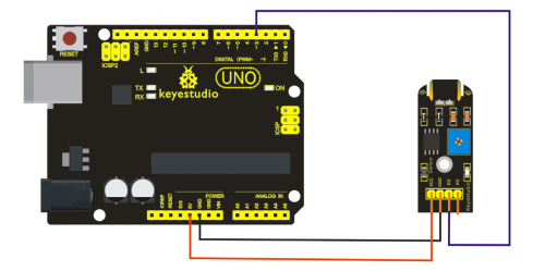
What's the simplest way to check vibration with Arduino? Well, use a vibration sensor from keyestudio. You can directly plug it on our sensor Shield V5, vibrate this sensor, and Arduino can receive a digital signal, making it easy to make computation and programs in Arduino. Despite its simplicity, you can make full use of it with creative thinking, step counting, and crash warning light etc.
Specification
IO Type: Digital
Supply Voltage: 3.3V to 5V
Size: 40.7*16.7mm
Weight: 5g
Connection Diagram
Sample Code
	#define SensorLED     13
#define SensorINPUT   3  //Connect the sensor to digital Pin 3 which is Interrupts 1.
 unsigned char state = 0;
 void setup()
{
  pinMode(SensorLED, OUTPUT);
  pinMode(SensorINPUT, INPUT);
  attachInterrupt(1, blink, FALLING);// Trigger the blink function when the falling edge is detected
  }
void loop()
{  if(state!=0)
      {
        state = 0;
        digitalWrite(SensorLED,HIGH);
        delay(500);
      }
      else
        digitalWrite(SensorLED,LOW);
}
void blink()//Interrupts function
{  state++;
}
Project 17: DS3231 Clock Module
Introduction
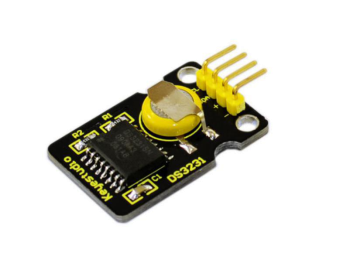
DS3231 is equipped with integrated TCXO and crystal, which makes it a cost-effective I2C real time clock with high precision. The device carries a battery input, so if you disconnect the main power supply, it can still maintain accurate timing. The integrated oscillator ensures the long-term accuracy of the device and reduces the number of components. DS3231 provides both commercial and industrial temperature range and supports 16 pins small-outline package (300mil). The module itself can adapt to the system of 3.3V and 5V without level switch, which is quite convenient!
Specification
Temperature range: -40 to +85; Timing accuracy : ± 5ppm (±0.432 seconds / day)
Provide battery backup for continuous timing
Low power consumption
Device package and function compatible with DS3231
Complete clock calendar function contains seconds and minutes, hour, week, date, month, and year timing and provides leap year compensation until 2100.
Two calendar clock
Output: 1Hz and 32.768kHz
Reset output and Input Debounce of Pushbutton
High speed (400kHz), I2C serial bus
Supply voltage: +3.3V to +5.5V
Digital temperature sensor with a precision of±3℃
Working temperature: -40 ~ C to +85 ~ C
16 pins Small Outline Package (300mil)
Certified by American Association of Underwriters Laboratories (UL)
Size: 30*20mm
Weight: 4g
Connection Diagram
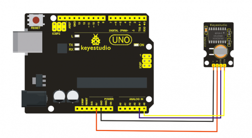
This module adopts the IIC test method, so we only need to connect ‘SDA’ to Arduino A4, ‘SCL’ to A5, ‘+’ to VCC and ‘-’ to GND as follows:
Sample Code
#include <Wire.h>
#include "DS3231.h"
DS3231 RTC; //Create the DS3231 object
char weekDay[][4] = {"Sun", "Mon", "Tue", "Wed", "Thu", "Fri", "Sat" };
//year, month, date, hour, min, sec and week-day(starts from 0 and goes to 6)
//writing any non-existent time-data may interfere with normal operation of the RTC.
//Take care of week-day also.
DateTime dt(2011, 11, 10, 15, 18, 0, 5);//open the series port and you can check time here or make a change to the time as needed.
void setup ()
{   Serial.begin(57600);//set baud rate to 57600
    Wire.begin();
    RTC.begin();
    RTC.adjust(dt); //Adjust date-time as defined 'dt' above
}
void loop ()
{
 DateTime now = RTC.now(); //get the current date-time
    Serial.print(now.year(), DEC);
    Serial.print('/');
    Serial.print(now.month(), DEC);
    Serial.print('/');
    Serial.print(now.date(), DEC);

    Serial.print(' ');
    Serial.print(now.hour(), DEC);
    Serial.print(':');
    Serial.print(now.minute(), DEC);
    Serial.print(':');
    Serial.print(now.second(), DEC);
    Serial.println();
    Serial.print(weekDay[now.dayOfWeek()]);
    Serial.println();
    delay(1000);
}
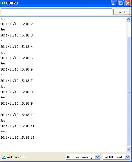
Before compiling the code, you’d better put DS3231 library under file into Arduino catalogue,. When the above steps are done, you can upload the code to arduino and open the series monitor and get following results:
Project 18: keyestudio MQ135 Air Quality Sensor
Introduction
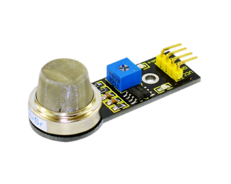
MQ135 adopts SnO2 as its gas sensitive material because SnO2 has low electrical conductivity in the clean air. So when surrounded by polluted air, the electrical conductivity of MQ135 will increase with the increase of pollutants, and the change in electrical conductivity can be converted to corresponding output signal.
MQ135 has a high sensitivity to Ammonia, sulfide, benzene vapor, smoke and other harmful gas. It can detect various harmful gases, making it a cost-effective choice suitable for multiple applications.
Specification
Product model: MQ135
Product type: Semiconductor gas sensor
Standard Package: Bakelite (Black Bakelite)
Target gas: Ammonia; methylbenzene; hydrogen
Standard circuit: Loop voltage Vc ≤24V DC
Heater voltage: VH 5.0V±0.2V AC or DC
Load resistance: Adjustable RL
Features of sensitive components under standard test condition: Heating resistor RH 31Ω±3Ω (room temperature)
Heater power consumption: PH ≤900mW
Surface resistance of sensitive material: Rs 2KΩ-20KΩ(in 100ppm NH3)
Sensitivity: S Rs(in air)/Rs(100ppmNH3)≥5
Concentration slope: α ≤0.6(R100ppm/R50ppm NH3)
Standard testing temperature/humidity : 20℃±2℃/65%±5%RH
Standard testing circuit: Vc:5.0V±0.1V
VH: 5.0V±0.1V
Preheating time: ≧48H
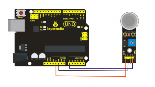
Connection diagram
Sample code
/*
  AnalogReadSerial
 Reads an analog input on pin 0, prints the result to the serial monitor

 This example code is in the public domain.
 */

void setup() {
  Serial.begin(9600);
}

void loop() {
  int sensorValue = analogRead(A0);
  Serial.println(sensorValue, DEC);

}
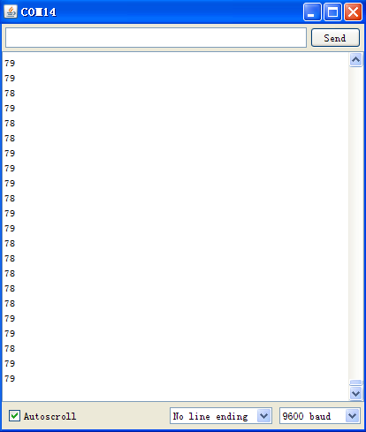
Turn on Serial monitor to check the pollution index of the air surrounds you:
Project 19: Color Sensor
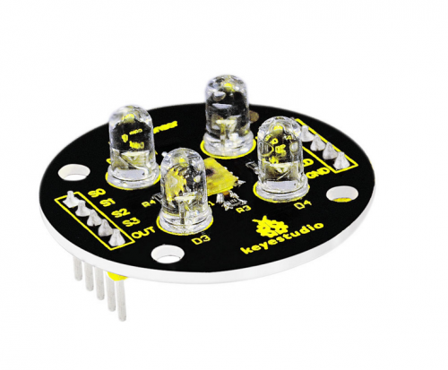
Introduction
TCS3200 programmable color light-to-frequency converter applies to colorimeter measurement such as color printing, medical diagnosis, calibration of PC color monitor as well as process control and color coordination in oil paint, textile, cosmetics and printing material industries.
TCS3200 is built on the principle of three primary colors. Concretely speaking, TCS3200 allows only one specific primary color to go through and blocks other primary colors if a specific color filter was chosen. For example, when red filter was chosen, only red light can pass through while blue and green lights will be blocked out, so that we can get the intensity of red light. The strength of blue and green lights can be got in the same way. Finally, By analyzing the light strength of these three color, we can recognize the color reflected onto TCS3200.
Specification
Color Recognition Sensor Module
Condition: New
Chip: TCS230
Input voltage: DC 3 ~ 5V
Output frequency voltage: 0 ~ 5V
Use high brightness white LEDs
Can be connected directly to Microcontroller
Static detection of the measured object color
Best detection distance: 10mm
Color and more details are shown as pictures
PLS NOTE that due to lighting effects, difference in monitor's brightness/ contrast settings etc, there could be some slight differences in the color tone between the pictures and the actual item!
Connection diagram
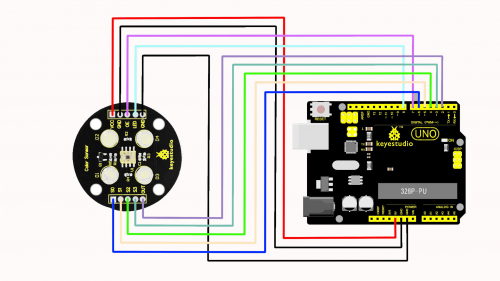
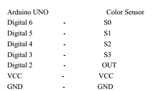
There are in total 10 pins on this sensor and among them, these two pins, namely GND and LED, are directly connected to each other by Jumper Cap. The following is the correct connection between this color sensor and Arduino UNO:
Sample code
#include <TimerOne.h>
#define S0 6 // Please notice the Pin's define
#define S1 5


#define S2 4
#define S3 3
#define OUT 2
int g_count = 0; // count the frequecy
int g_array[3]; // store the RGB value
int g_flag = 0; // filter of RGB queue
float g_SF[3]; // save the RGB Scale factor
// Init TSC230 and setting Frequency.
void TSC_Init()
{
pinMode(S0, OUTPUT);
pinMode(S1, OUTPUT);
pinMode(S2, OUTPUT);
pinMode(S3, OUTPUT);
pinMode(OUT, INPUT);
digitalWrite(S0, LOW); // OUTPUT FREQUENCY SCALING 2%
digitalWrite(S1, HIGH);
}
// Select the filter color
void TSC_FilterColor(int Level01, int Level02)
{
if(Level01 != 0)
Level01 = HIGH;
if(Level02 != 0)
Level02 = HIGH;
digitalWrite(S2, Level01);
digitalWrite(S3, Level02);
}
void TSC_Count()
{
g_count ++ ;
}
void TSC_Callback()
{
switch(g_flag)
{
case 0:
Serial.println("->WB Start");
TSC_WB(LOW, LOW); //Filter without Red
break;
case 1:
Serial.print("->Frequency R=");


Serial.println(g_count);
g_array[0] = g_count;
TSC_WB(HIGH, HIGH); //Filter without Green
break;
case 2:
Serial.print("->Frequency G=");
Serial.println(g_count);
g_array[1] = g_count;
TSC_WB(LOW, HIGH); //Filter without Blue
break;
case 3:
Serial.print("->Frequency B=");
Serial.println(g_count);
Serial.println("->WB End");
g_array[2] = g_count;
TSC_WB(HIGH, LOW); //Clear(no filter)
break;
default:
g_count = 0;
break;
}
}
void TSC_WB(int Level0, int Level1) //White Balance
{
g_count = 0;
g_flag ++;
TSC_FilterColor(Level0, Level1);
Timer1.setPeriod(1000000); // set 1s period
}
void setup()
{
TSC_Init();
Serial.begin(9600);
Timer1.initialize(); // defaulte is 1s
Timer1.attachInterrupt(TSC_Callback);
attachInterrupt(0, TSC_Count, RISING);
delay(4000);
for(int i=0; i<3; i++)
Serial.println(g_array[i]);
g_SF[0] = 255.0/ g_array[0]; //R Scale factor
g_SF[1] = 255.0/ g_array[1] ; //G Scale factor
g_SF[2] = 255.0/ g_array[2] ; //B Scale factor


Serial.println(g_SF[0]);
Serial.println(g_SF[1]);
Serial.println(g_SF[2]);
}
void loop()
{
g_flag = 0;
for(int i=0; i<3; i++)
Serial.println(int(g_array[i] * g_SF[i]));
delay(4000);
}
Resources
Video
http://www.keyestudio.com/wp/2016/05/ks0180-keyestudio-sensor-kit-for-arduino-starters-k3/
https://drive.google.com/open?id=1c2c83XY8d-PupQzRyCxn48lTlJ5YSJp6
Buy from
Official Website
http://www.keyestudio.com/keyestudio-sensor-kit-for-arduino-starters-k3.html
Amazon Store
