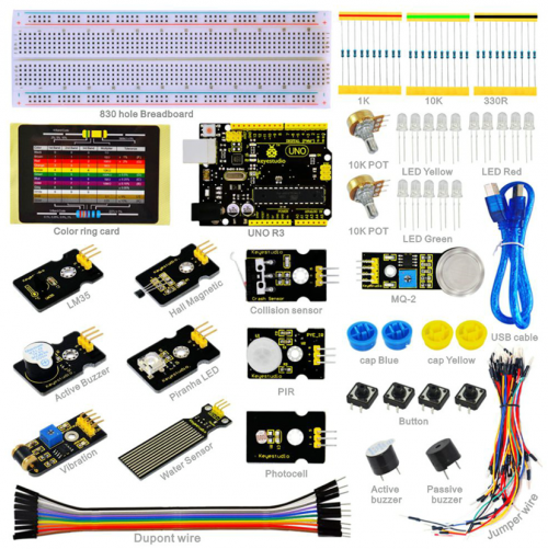
Ks0179 keyestudio Sensor Kit for ARDUINO starters- K2
keyestudio Sensor Kit for ARDUINO starters- K2
Introduction
This keyestudio Sensor Kit is an Arduino stater learning kit developed by Keyes. We provide detailed tutorials for each project or sensor module, including connection diagrams and sample codes, with which you will find it easy for you to complete every experiments. Besides, you can also find video tutorials of this kit on our official website.
Component List
Project Details
Project 1: Hello World
Introduction
As for starters, we will begin with something simple. In this project, you only need an Arduino and a USB cable to start the "Hello World!" experiment. This is a communication test of your Arduino and PC, also a primer project for you to have your first try of the Arduino world!
Hardware required
Arduino board *1
USB cable *1
Sample program
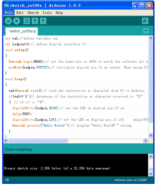
After installing driver for Arduino, let's open Arduino software and compile code that enables Arduino to print "Hello World!" under your instruction. Of course, you can compile code for Arduino to continuously echo "Hello World!" without instruction. A simple If () statement will do the instruction trick. With the onboard LED connected to pin 13, we can instruct the LED to blink first when Arduino gets an instruction and then print "Hello World!”.
int val;//define variable val
int ledpin=13;// define digital interface 13
void setup()
{
  Serial.begin(9600);// set the baud rate at 9600 to match the software set up. When connected to a specific device, (e.g. bluetooth), the baud rate needs to be the same with it.
  pinMode(ledpin,OUTPUT);// initialize digital pin 13 as output. When using I/O ports on an Arduino, this kind of set up is always needed.
}
void loop()
{
  val=Serial.read();// read the instruction or character from PC to Arduino, and assign them to Val.
  if(val=='R')// determine if the instruction or character received is “R”.
  {  // if it’s “R”,
    digitalWrite(ledpin,HIGH);// set the LED on digital pin 13 on.
    delay(500);
digitalWrite(ledpin,LOW);// set the LED on digital pin 13 off.
 delay(500);
    Serial.println("Hello World!");// display“Hello World!”string.
  }
}
Result
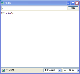
Click serial port monitor,Input R,LED 13 will blink once,PC will receive information from Arduino: Hello World
After you choosing the right port,the experiment should be easy for you!
Project 2: LED blinking
Introduction
Blinking LED experiment is quite simple. In the "Hello World!" program, we have come across LED. This time, we are going to connect an LED to one of the digital pins rather than using LED13, which is soldered to the board. Except an Arduino and an USB cable, we will need extra parts as below:
Hardware required
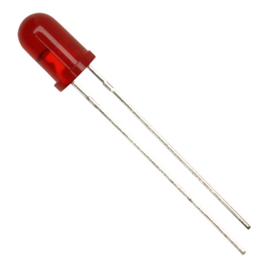
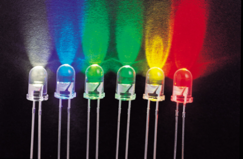
Red M5 LED*1
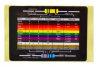
220Ω resistor*1
Breadboard*1
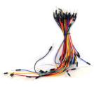
Breadboard jumper wires
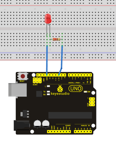
Circuit connection We follow below diagram from the experimental schematic link. Here we use digital pin 10. We connect LED to a 220 ohm resistor to avoid high current damaging the LED.
Sample program
int ledPin = 10; // define digital pin 10.
void setup()
{
pinMode(ledPin, OUTPUT);// define pin with LED connected as output.
}
void loop()
{
digitalWrite(ledPin, HIGH); // set the LED on.
delay(1000); // wait for a second.
digitalWrite(ledPin, LOW); // set the LED off.
delay(1000); // wait for a second
}
Result
After downloading this program, in the experiment, you will see the LED connected to pin 10 turning on and off, with an interval approximately one second. The LED blinking experiment is now complete. Thank you!
Project 3: PWM
Introduction
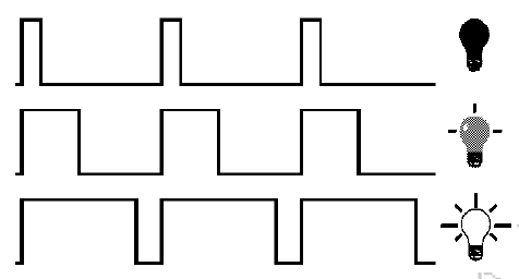
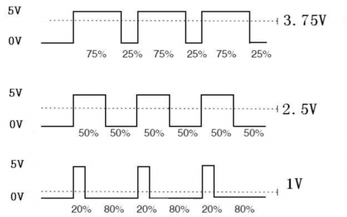
PWM, short for Pulse Width Modulation, is a technique used to encode analog signal level into digital ones. A computer cannot output analog voltage but only digital voltage values such as 0V or 5V. So we use a high resolution counter to encode a specific analog signal level by modulating the duty cycle of PMW. The PWM signal is also digitalized because in any given moment, fully on DC power supply is either 5V (ON), or 0V (OFF). The voltage or current is fed to the analog load (the device that uses the power) by repeated pulse sequence being ON or OFF. Being on, the current is fed to the load; being off, it's not. With adequate bandwidth, any analog value can be encoded using PWM. The output voltage value is calculated via the on and off time. Output voltage = (turn on time/pulse time) * maximum voltage value
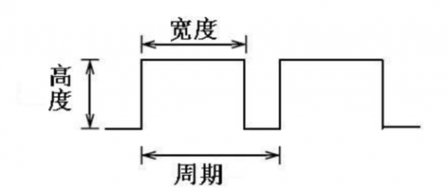
PWM has many applications: lamp brightness regulating, motor speed regulating, sound making, etc. The following are the three basic parameters of PMW:
1. The amplitude of pulse width (minimum / maximum)
2. The pulse period (The reciprocal of pulse frequency in 1 second)
3. The voltage level(such as:0V-5V)
There are 6 PMW interfaces on Arduino, namely digital pin 3, 5, 6, 9, 10, and 11. In previous experiments, we have done "button-controlled LED", using digital signal to control digital pin, also one about potentiometer. This time, we will use a potentiometer to control the brightness of the LED.
Hardware required
Potentiometer module*1
Red M5 LED*1
220Ω resistor
Breadboard*1
Breadboard jumper wires
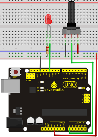
Circuit connection
The input of potentiometer is analog, so we connect it to analog port, and LED to PWM port. Different PWM signal can regulate the brightness of the LED.
Sample program
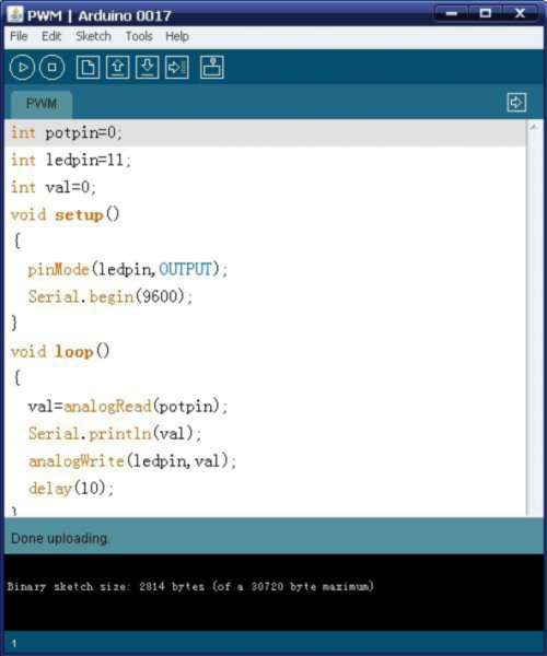
In the program compiling process, we will use the analogWrite (PWM interface, analog value) function. In this experiment, we will read the analog value of the potentiometer and assign the value to PWM port, so there will be corresponding change to the brightness of the LED. One final part will be displaying the analog value on the screen. You can consider this as the "analog value reading" project adding the PWM analog value assigning part. Below is a sample program for your reference.
int potpin=0;// initialize analog pin 0
int ledpin=11;//initialize digital pin 11(PWM output)
int val=0;// Temporarily store variables' value from the sensor
void setup()
{
pinMode(ledpin,OUTPUT);// define digital pin 11 as “output”
Serial.begin(9600);// set baud rate at 9600
// attention: for analog ports, they are automatically set up as “input”
}
void loop()
{
val=analogRead(potpin);// read the analog value from the sensor and assign it to val
Serial.println(val);// display value of val
analogWrite(ledpin,val/4);// turn on LED and set up brightness(maximum output of PWM is 255)
delay(10);// wait for 0.01 second
}
Result
After downloading the program, when we rotate the potentiometer knob, we can see changes of the displaying value, also obvious change of the LED brightness on the breadboard.
Project 4: Traffic light
Introduction
In the previous program, we have done the LED blinking experiment with one LED. Now, it’s time to up the stakes and do a bit more complicated experiment-traffic lights. Actually, these two experiments are similar. While in this traffic lights experiment, we use 3 LEDs with different color other than 1 LED.
Hardware required
Arduino board *1
USB cable *1
Red M5 LED*1
Yellow M5 LED*1
Green M5 LED*1
220Ω resistor *3
Breadboard*1
Breadboard jumper wires
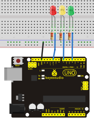
Circuit connection
Sample program
Since it is a simulation of traffic lights, the blinking time of each LED should be the same with those in traffic lights system. In this program, we use Arduino delay () function to control delay time, which is much simpler than C language.
int redled =10; // initialize digital pin 8.
int yellowled =7; // initialize digital pin 7.
int greenled =4; // initialize digital pin 4.
void setup()
{
pinMode(redled, OUTPUT);// set the pin with red LED as “output”
pinMode(yellowled, OUTPUT); // set the pin with yellow LED as “output”
pinMode(greenled, OUTPUT); // set the pin with green LED as “output”
}
void loop()
{
digitalWrite(greenled, HIGH);//// turn on green LED
delay(5000);// wait 5 seconds
digitalWrite(greenled, LOW); // turn off green LED
for(int i=0;i<3;i++)// blinks for 3 times
{
delay(500);// wait 0.5 second
digitalWrite(yellowled, HIGH);// turn on yellow LED
delay(500);// wait 0.5 second
digitalWrite(yellowled, LOW);// turn off yellow LED
}
delay(500);// wait 0.5 second
digitalWrite(redled, HIGH);// turn on red LED
delay(5000);// wait 5 second
digitalWrite(redled, LOW);// turn off red LED
}
Result
When the uploading process is completed, we can see traffic lights of our own design. Note: this circuit design is very similar with the one in LED chase effect. The green light will be on for 5 seconds, and then off., followed by the yellow light blinking for 3 times, and then the red light on for 5 seconds, forming a cycle. Cycle then repeats. Experiment is now completed, thank you.
Project 5: LED chasing effect
Introduction
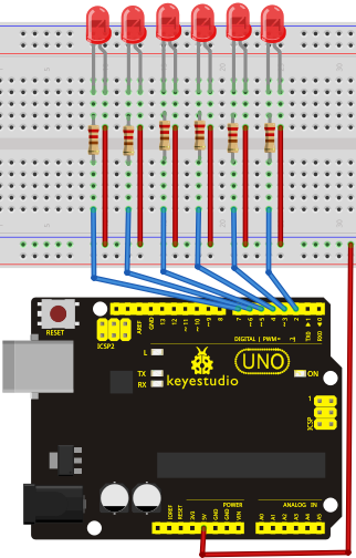
We often see billboards composed of colorful LEDs. They are constantly changing to form various effects. In this experiment, we compile a program to simulate chase effect.
Hardware required
Led *6
220Ω resistor *6
Breadboard jumper wires
Circuit connection
Sample program
int BASE = 2 ;  // the I/O pin for the first LED
int NUM = 6;   // number of LEDs

void setup()
{
   for (int i = BASE; i < BASE + NUM; i ++)
   {
     pinMode(i, OUTPUT);   // set I/O pins as output
   }
}

void loop()
{
   for (int i = BASE; i < BASE + NUM; i ++)
   {
     digitalWrite(i, LOW);    // set I/O pins as “low”, turn off LEDs one by one.
     delay(200);        // delay
   }
   for (int i = BASE; i < BASE + NUM; i ++)
   {
     digitalWrite(i, HIGH);    // set I/O pins as “high”, turn on LEDs one by one
     delay(200);        // delay
   }
}
Result
You can see the LEDs blink by sequence.
Project 6: Button-controlled LED
Introduction
I/O port means interface for INPUT and OUTPUT. Up until now, we have only used its OUTPUT function. In this experiment, we will try to use the input function, which is to read the output value of device connecting to it. We use 1 button and 1 LED using both input and output to give you a better understanding of the I/O function. Button switches, familiar to most of us, are a switch value (digital value) component. When it's pressed, the circuit is in closed (conducting) state.
Hardware required
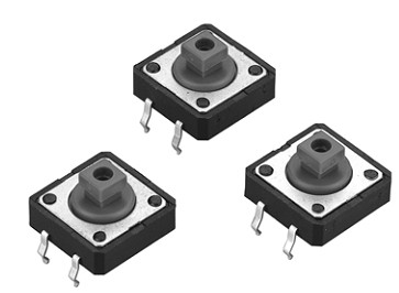
Button switch*1
Red M5 LED*1
220Ω resistor*1
10KΩ resistor*1
Breadboard*1
Breadboard jumper wires
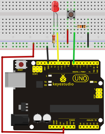
Circuit connection
Sample program
Now, let's begin the compiling. When the button is pressed, the LED will be on. After the previous study, the coding should be easy for you. In this program, we add a statement of judgment. Here, we use an if () statement.
Arduino IDE is based on C language, so statements of C language such as while, switch etc. can certainly be used for Arduino program.
When we press the button, pin 7 will output high level. We can program pin 11 to output high level and turn on the LED. When pin 7 outputs low level, pin 11 also outputs low level and the LED remains off.
int ledpin=11;// initialize pin 11
int inpin=7;// initialize pin 7
int val;// define val
void setup()
{
pinMode(ledpin,OUTPUT);// set LED pin as “output”
pinMode(inpin,INPUT);// set button pin as “input”
}
void loop()
{
val=digitalRead(inpin);// read the level value of pin 7 and assign if to val
if(val==LOW)// check if the button is pressed, if yes, turn on the LED
{ digitalWrite(ledpin,LOW);}
else
{ digitalWrite(ledpin,HIGH);}
}
Result
When the button is pressed, LED is on, otherwise, LED remains off. After the above process, the button controlled LED experiment is completed. The simple principle of this experiment is widely used in a variety of circuit and electric appliances. You can easily come across it in your every day life. One typical example is when you press a certain key of your phone, the backlight will be on.
Project 7: Responder experiment
Introduction
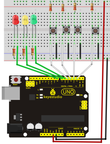
After completing all the previous experiments, we believe you will find this one easy. In this program, we have 3 buttons and a reset button controlling the corresponding 3 LEDs, using 7 digital I/O pins.
Hardware required
Button switch*4
Red M5 LED*1
Yellow M5 LED*1
Green M5 LED*1
220Ω resistor*3
10KΩ resistor*4
Breadboard*1
Breadboard jumper wires
Circuit connection
Sample program
int redled=8;     // set red LED as “output”
int yellowled=7;  // set yellow LED as “output”
int greenled=6;   // set green LED as “output”
int redpin=5;     // initialize pin for red button
int yellowpin=4;  // initialize pin for yellow button
int greenpin=3;   // initialize pin for green button
int restpin=2;   // initialize pin for reset button
int red;
int yellow;
int green;
void setup()
{
pinMode(redled,OUTPUT);
pinMode(yellowled,OUTPUT);
pinMode(greenled,OUTPUT);
pinMode(redpin,INPUT);
pinMode(yellowpin,INPUT);
pinMode(greenpin,INPUT);
}
void loop()  // repeatedly read pins for buttons
{
red=digitalRead(redpin);
yellow=digitalRead(yellowpin);
green=digitalRead(greenpin);
if(red==LOW)RED_YES();
if(yellow==LOW)YELLOW_YES();
if(green==LOW)GREEN_YES();
}

void RED_YES()// execute the code until red light is on; end cycle when reset button is pressed
{
  while(digitalRead(restpin)==1)
  {
   digitalWrite(redled,HIGH);
   digitalWrite(greenled,LOW);
   digitalWrite(yellowled,LOW);
  }
  clear_led();
}
void YELLOW_YES()// execute the code until yellow light is on; end cycle when reset button is pressed
{
  while(digitalRead(restpin)==1)
  {
  digitalWrite(redled,LOW);
  digitalWrite(greenled,LOW);
  digitalWrite(yellowled,HIGH);
  }
  clear_led();
}
void GREEN_YES()// execute the code until green light is on; end cycle when reset button is pressed
{
  while(digitalRead(restpin)==1)
  {
  digitalWrite(redled,LOW);
  digitalWrite(greenled,HIGH);
  digitalWrite(yellowled,LOW);
  }
  clear_led();
}
void clear_led()// all LED off
{
  digitalWrite(redled,LOW);
  digitalWrite(greenled,LOW);
  digitalWrite(yellowled,LOW);
}
Result
Whichever button is pressed first, the corresponding LED will be on! Then press the REST button to reset. After the above process, we have built our own simple responder.
Project 8: Active buzzer
Introduction
Arduino enables us to make many interesting interactive projects, many of which we have done consists of a LED. They are light-related. While this time, the circuit will produce sound. The sound experiment is usually done with a buzzer or a speaker, while buzzer is simpler and easier to use. The buzzer we introduced here is a passive buzzer. It cannot be actuated by itself, but by external pulse frequencies. Different frequencies produce different sounds. We can use Arduino to code the melody of a song, which is actually fun and simple.
Hardware required
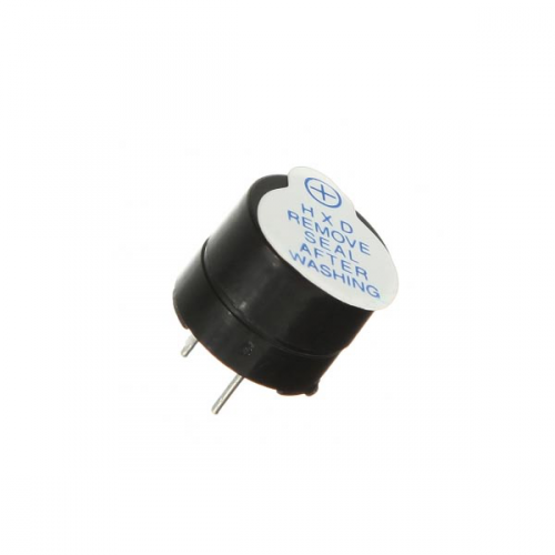
Buzzer*1
Key *1
Breadboard*1
Breadboard jumper wires
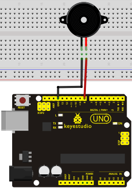
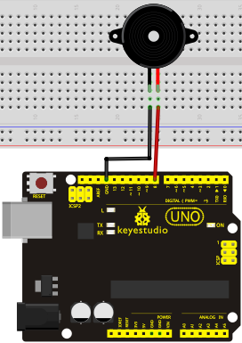
Circuit connection
When connecting the circuit, pay attention to the positive & the negative poles of the buzzer. In the photo, you can see there are red and black lines. When the circuit is finished, you can begin programming.
Sample program
Program is simple. You control the buzzer by outputting high/low level.
int buzzer=8;// initialize digital IO pin that controls the buzzer
void setup()
{
  pinMode(buzzer,OUTPUT);// set pin mode as “output”
}
void loop()
{
digitalWrite(buzzer, HIGH); // produce sound
}
Result
After downloading the program, the buzzer experiment is completed. You can see the buzzer is ringing.
Project 9: Passive buzzer
Introduction
We can use Arduino to make many interactive works of which the most commonly used is acoustic-optic display. All the previous experiment has something to do with LED. However, the circuit in this experiment can produce sound. Normally, the experiment is done with a buzzer or a speaker while buzzer is simpler and easier to use. The buzzer we introduced here is a passive buzzer. It cannot be actuated by itself, but by external pulse frequencies. Different frequencies produce different sounds. We can use Arduino to code the melody of a song, which is actually quite fun and simple.
Hardware required
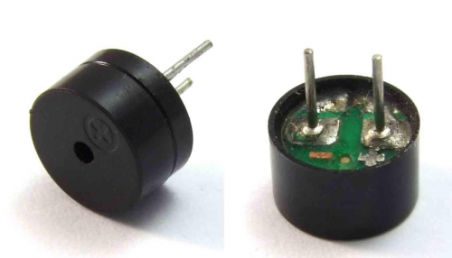
Passive buzzer*1
Key *1
Breadboard*1
Breadboard jumper wires
Circuit connection
Sample program
int buzzer=8;// select digital IO pin for the buzzer
void setup()
{
pinMode(buzzer,OUTPUT);// set digital IO pin pattern, OUTPUT to be output
}
void loop()
{ unsigned char i,j;//define variable
while(1)
{ for(i=0;i<80;i++)// output a frequency sound
{ digitalWrite(buzzer,HIGH);// sound
delay(1);//delay1ms
digitalWrite(buzzer,LOW);//not sound
delay(1);//ms delay
}
for(i=0;i<100;i++)// output a frequency sound
{ digitalWrite(buzzer,HIGH);// sound
digitalWrite(buzzer,LOW);//not sound
delay(2);//2ms delay
}
}
}
After downloading the program, buzzer experiment is finished.
Project 10: Piranha LED Module
Introduction
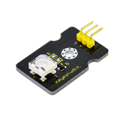
This is a special LED module. When you connect it to ARDUINO development board, after program, it can emit beautiful light. Of course, you can also control it using PWM. It will be like fireflies at night. Isn’t cool? We can also combine it with other sensors to do various interesting interactive experiments.
Specification
Module type: digital
Working voltage: 5v
Distance between pins: 2.54mm
Size: 30*20mm
Weight: 3g
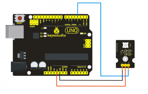
Connection Diagram
Sample Code
int led = 3;
void setup()
{
  pinMode(led, OUTPUT);     //Set Pin3 as output
}
void loop()
{      digitalWrite(led, HIGH);   //Turn off led
          delay(2000);
          digitalWrite(led, LOW);    //Turn on led
          delay(2000);
}
Project 11: Digital Buzzer Module
Introduction
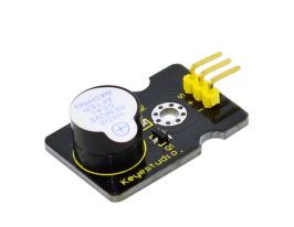
Here is the simplest sound making module. You can use high/low level to drive it. Changing the frequency it buzzes can produce different sound. This module is widely used on your daily appliance, like PC, refrigerator, phones etc. And you can also create many interesting interactive project with this small but useful module. Just try it!! You will find the electronic sound it creates so fascinating.
Specification
Working voltage: 3.3-5v
Interface type: digital
Size: 30*20mm
Weight: 4g
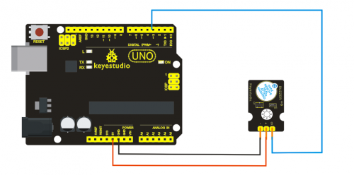
Connection Diagram
Sample Code
int buzzPin =  3;    //Connect Buzzer on Digital Pin3
 void setup()
 {
  pinMode(buzzPin, OUTPUT);
}
 void loop()
{
  digitalWrite(buzzPin, HIGH);
  delay(1);
  digitalWrite(buzzPin, LOW);
  delay(1);
}
Project 12: Hall Magnetic Sensor
Introduction
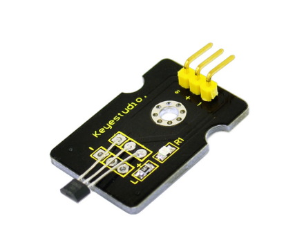
This is a Magnetic Induction Sensor. It senses the magnetic materials within a detection range up to 3cm. The detection range and the strength of the magnetic field are proportional. The output is digital on/off. This sensor uses the SFE Reed Switch - Magnetic Field Sensor.
Specification
Sensing magnetic materials
Detection range: up to 3cm
Output: digital on/off
Detection range and magnetic field strength are proportional
Size: 30*20mm
Weight: 3g
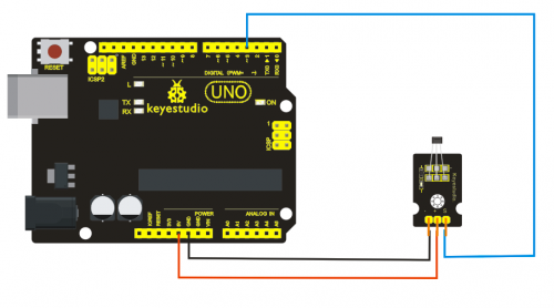
Connection Diagram
Sample Code
int ledPin = 13;                // choose the pin for the LED
int inputPin = 3;               // Connect sensor to input pin 3
int val = 0;                    // variable for reading the pin status

void setup() {
  pinMode(ledPin, OUTPUT);      // declare LED as output
  pinMode(inputPin, INPUT);     // declare pushbutton as input
}
Project 13: Keyestudio collision sensor
Introduction
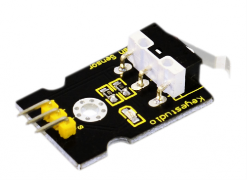
Collision sensor, also known as electronic switch, is a digital on-off input module necessary for elementary electronic learning. By programming, it can realize control over light, sound device, key choice function of LCD display etc. Using 3P sensor cable to connect it to sensor shield, it can be installed to 4WD AL alloy mobile robot platform to realize collision detection function. It is both convenient and effecient.
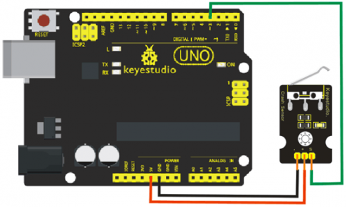
Note: You can make a collision flasher using collision module and built-in LED on interface 13. Connect the collision senser to pin 3, when the collision sensor senses a collision signal, the LEDs on mainboard and module will light up simultaneously.
Specification
1. If collision happens upfront of where collision module is installed, module outputs low level signal; no collision, outputs high level signal.
2. Module reserves M3 mounting hole, convenient for fixation on a car.
3. Module size: 3.1cm * 2.1cm
4. With switch indicator light, if there is collision, light is on; no collision, light is out.
Pin definition
1 +   3v-12v power supply

2 -   GND

3 S   Gigh-low level output
Circuit connection
Sample program
int ledPin = 13;                // choose the pin for the LED
int inputPin = 3;               // Connect sensor to input pin 3
int val = 0;                    // variable for reading the pin status

void setup() {
  pinMode(ledPin, OUTPUT);      // declare LED as output
  pinMode(inputPin, INPUT);     // declare pushbutton as input
}

void loop(){
  val = digitalRead(inputPin);  // read input value
  if (val == HIGH) {            // check if the input is HIGH
    digitalWrite(ledPin, LOW);  // turn LED OFF
  } else {
    digitalWrite(ledPin, HIGH); // turn LED ON
  }
}
Project 14: LM35 Linear Temperature Sensor
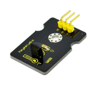
Introduction
LM35 Linear Temperature Sensor is based on semiconductor LM35 temperature sensor. It can be used to detect ambient air temperature. This sensor offers a functional range among 0 degree Celsius to 100 degree Celsius. Sensitivity is 10mV per degree Celsius. The output voltage is proportional to the temperature.
This sensor is commonly used as a temperature measurement sensor. It includes thermocouples, platinum resistance, and thermal resistance and temperature semiconductor chips. The chip is commonly used in high temperature measurement thermocouples. Platinum resistance temperature sensor is used in the measurement of 800 degrees Celsius, while the thermal resistance and semiconductor temperature sensor is suitable for measuring the temperature of 100-200 degrees or below, in which the application of a simple semiconductor temperature sensor is good in linearity and high in sensitivity. The LM35 linear temperature sensor and sensor-specific Arduino shield can be easily combined.
Specification
Based on the semiconductor LM35 temperature sensor
Can be used to detect ambient air temperature
Sensitivity: 10mV per degree Celcius
Functional range: 0 degree Celsius to 100 degree Celsius
Size: 30*20mm
Weight: 3g
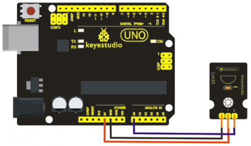
Connection Diagram
Sample Code
void setup()
{
    Serial.begin(9600);//Set Baud Rate to 9600 bps
}
 void loop()
{  int val;
    int dat;
    val=analogRead(0);//Connect LM35 on Analog 0
    dat=(500 * val) /1024;;
    Serial.print("Temp:"); //Display the temperature on Serial monitor
    Serial.print(dat);
    Serial.println("C");
    delay(500);
}
Project 15: Photocell sensor
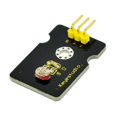
Introduction
Photocell is commonly seen in our daily life and is mainly used in intelligent switch, also in common electronic design. To make it easier and more effective, we supply corresponding modules.
Photocell is a semiconductor. It has features of high sensitivity, quick response, spectral characteristic, and R-value consistence, maintaining high stability and reliability in environment extremes such as high temperature, high humidity. It’s widely used in automatic control switch fields like cameras, garden solar lights, lawn lamps, money detectors, quartz clocks, music cups, gift boxes, mini night lights, sound and light control switches, etc.
Specification
Interface type: analog
Working voltage: 5V
Size: 30*20mm
Weight: 3g
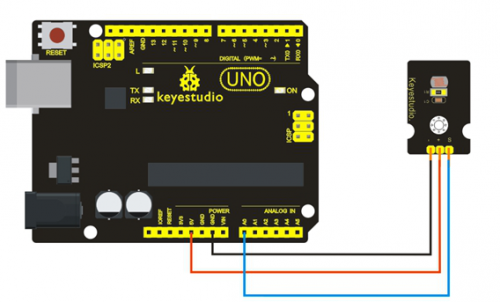
Connection Diagram
Sample Code
int sensorPin =A0 ;
int value = 0;
void setup()
{
 Serial.begin(9600); }
void loop()
{
 value = analogRead(sensorPin);

Serial.println(value, DEC);

delay(50);
}
Project 16: Vibration Sensor
Introduction
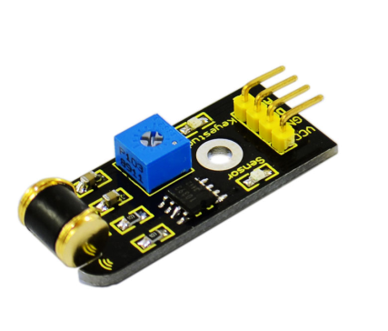
What's the simplest way to check vibration with Arduino? Well, use a vibration sensor from keyestudio. You can directly plug it on our sensor Shield V5, vibrate this sensor, and Arduino can receive a digital signal, making it easy to make computation and programs in Arduino. Despite its simplicity, you can make full use of it with creative thinking, step counting, and crash warning light etc.
Specification
IO Type: Digital
Supply Voltage: 3.3V to 5V
Size: 40.7*16.7mm
Weight: 5g
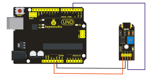
Connection Diagram
Sample Code
#define SensorLED     13
#define SensorINPUT   3  //Connect the sensor to digital Pin 3 which is Interrupts 1.
 unsigned char state = 0;
 void setup()
{
  pinMode(SensorLED, OUTPUT);
  pinMode(SensorINPUT, INPUT);
  attachInterrupt(1, blink, FALLING);// Trigger the blink function when the falling edge is detected
  }
void loop()
{  if(state!=0)
      {
        state = 0;
        digitalWrite(SensorLED,HIGH);
        delay(500);
      }
      else
        digitalWrite(SensorLED,LOW);
}
void blink()//Interrupts function
{  state++;
}
Project 17: Analog Gas Sensor
Introduction
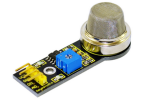
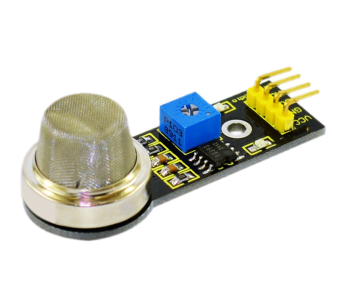
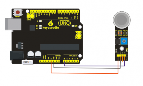
This analog gas sensor - MQ2 is used in gas leakage detecting equipment in consumer electronics and industrial markets. This sensor is suitable for detecting LPG, I-butane, propane, methane, alcohol, Hydrogen and smoke. It has high sensitivity and quick response. In addition, the sensitivity can be adjusted by the potentiometer.
Specification
Power supply: 5V
Interface type: Analog
Wide detecting scope
Quick response and High sensitivity
Simple drive circuit
Stable and long lifespan
Size: 49.7*20mm
Weight: 8g
Connection Diagram
Sample Code
///Arduino Sample Code
void setup()
{
  Serial.begin(9600); //Set serial baud rate to 9600 bps
}
void loop()
{
int val;
val=analogRead(0);//Read Gas value from analog 0
Serial.println(val,DEC);//Print the value to serial port
delay(100);
}
Project 18: keyestudio Water Sensor
Introduction
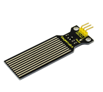
Our water sensor is easy- to-use, portable and cost-effective, designed to identify and detect water level and water drop. This sensor measures the volume of water drop and water quantity through an array of traces of exposed parallel wires. Compared with its competitors, this sensor is not only smaller and smarter but also ingeniously equipped with following features:
i)smooth conversion between water quantity and analog quantity;
ii)strong flexibility, this sensor outputs basic analog value;
iii)low power consumption and high sensitivity;
iv)directly connected to microprocessor or other logic circuits, suitable for a variety of development boards and controllers such as Arduino controller, STC single-chip microcomputer, AVR single-chip microcomputer etc.
Specification
Product name: Water Sensor
Operating voltage: DC5V
Operating current: ﹤20mA
Sensor type: Analog
Detection area: 40mm x16mm
Production process: FR4 double-side tinned
Humanized design: Anti-slippery semi-lunar recess
Operating temperature: 10%~90% without condensation
Product weight: 3g
Product size: 65mm x 20mm x 8mm
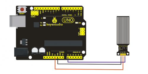
Connection Diagram
Sample Code
    int analogPin = 0; //connect water sensor to analog interface 0
int led = 13; //LED to digital interface 13
int val = 0; //define the initial value of variable ‘val’ as 0
int data = 0; //define the initial value of variable ‘data’ as 0
void setup()
{
pinMode(led, OUTPUT); //define led as output pin
Serial.begin(9600); //set baud rate at 9600
}
void loop()
{
val = analogRead(analogPin); //read and assign analog value to variable ’val’
if(val>700){ //decide whether variable ‘val’ is over 700 digitalWrite(led,HIGH); //turn on  LED when variable ‘val’ is over 700
}
else{
digitalWrite(led,LOW); //turn off LED when variable ‘val’ is under 700
}
data = val; //variable ’val’ assigns value to variable ‘data’
Serial.println(data); //print variable ‘data’ by Serial.print
delay(100);
}
After the above steps are done, let’s do a test on lower water level and check what happens: The LED can’t light up when water level haven’t reach alarm value; The LED turns on and released an alarm when water level reaches alarm value;
Project 19: PIR Motion Sensor
Introduction
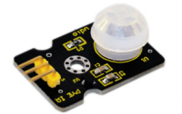
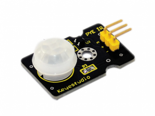
Pyroelectric infrared motion sensor can detect infrared signals from a moving person or moving animal, and output switching signals. It can be applied to a variety of occasions to detect the movement of human body. Conventional pyroelectric infrared sensors require body pyroelectric infrared detector, professional chip, complex peripheral circuit, so the size is bigger, with complex circuit, and lower reliability. Now we launch this new pyroelectric infrared motion sensor, specially designed for Arduino. It uses an integrated digital body pyroelectric infrared sensor, has smaller size, higher reliability, lower power consumption and simpler peripheral circuit.
Specification
Input Voltage: 3.3 ~ 5V, 6V Maximum
Working Current: 15uA
Working Temperature: -20 ~ 85 ℃
Output Voltage: High 3V, low 0V
Output Delay Time (High Level): About 2.3 to 3 Seconds
Detection angle: 100 °
Detection distance: 7 meters
Output Indicator LED (When output HIGH, it will be ON)
Pin limit current: 100mA
Size: 30*20mm
Weight: 4g
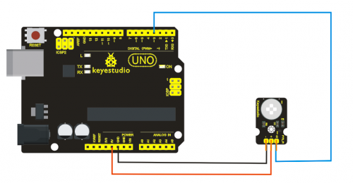
Connection Diagram
Sample Code
byte sensorPin = 3;
byte indicator = 13;
void setup()
{
  pinMode(sensorPin,INPUT);
  pinMode(indicator,OUTPUT);
  Serial.begin(9600);
}

void loop()
{
  byte state = digitalRead(sensorPin);
  digitalWrite(indicator,state);
  if(state == 1)Serial.println("Somebody is in this area!");
  else if(state == 0)Serial.println("No one!");
  delay(500);
}
Resources
Video
http://www.keyestudio.com/wp/ks0179/
https://drive.google.com/open?id=1CA-YxiJHCvmNln-hTuaWd3_zNYBWrHuj
Buy from
Official Website
http://www.keyestudio.com/keyestudio-sensor-kit-for-arduino-starters-k2.html
Amazon Store
https://www.amazon.com/New-keyestudio-Sensor-ARDUINO-starters/dp/B01DXDD5KW/
