KS0085 Keyestudio Smart Home Kit for Arduino

Instruction:

This Smart Home Learning Kit based on the Arduino platform is newly rolled out by Keyestudio DIY Robot Co. Ltd.
It simulates the real smart home and demonstrates the cozy and comfortable life for people.
This system adopts PLUS main control board and multiple modules, including 1602 LCD, photocell sensor, analog gas(MQ-2) sensor, PIR motion sensor, yellow LED, servo, steam sensor and Bluetooth.
In fact, Bluetooth controls everything in smart home: light intensity, humidity, flammable gas concentration, doors openning and closing. Everything is controlled via APPs on smart phones/IPad and will be displayed on 1602 LCD in real time.
We totally provide 3 programming languages: C language, Mixly and Scratch. These languages hit the top list in programming, which is easy and convenient to use and understand.
Kit List


Download software and install driver
Download software
When we get control board, we need to download Arduino IDE and driver firstly. You could download Arduino IDE from the official website: https://www.arduino.cc/, click the SOFTWARE on the browse bar, click “DOWNLOADS” to enter download page, as shown below:

There are various versions for Arduino, just download a suitable version for your system, we will take WINDOWS system as an example to show you how to download and install.

There are two versions for WINDOWS system, one is installed version, another one is download version, you just need to download file to computer directly and unzip it. These two versions can be used normally. Choose one and download on your computer.

You just need to click JUST DOWNLOAD, then click the downloaded file to install it. And when the ZIP file is downloaded, you can directly unzip and start it.
Keyestudio PLUS Control Board
Description

Keyestudio PLUS control board is fully compatible with Arduino IDE development environment. It contains all the functions of the Arduino UNO board. Moreover, some improvements we made highly strengthen its function. It is the best choice to learn how to build circuit and write code as well. Let’s get started!

- Serial communication interface: D0 is RX, D1 is TX
- PWM interface (pulse width modulation): D3 D5 D6 D9 D10 D11
- External interrupt interface: D2 (interrupt 0) and D3 (interrupt 1)
- SPI communication interface: D10 is SS, D11 is MOSI, D12 is MISO, D13 is SCK
- IIC communication port: A4 is SDA, A5 is SCL
Installing driver
Let’s install the driver of keyestudio PLUS control board. The USB-TTL chip on PLUS board adopts CP2102 serial chip. The driver program of this chip is included in Arduino 1.8 version and above, which is convenient. Plug on USB port of board, the computer can recognize the hardware and automatically install the driver of CP2102.
If install unsuccessfully, or you intend to install manually, open the device manager of computer. Right click Computer----- Properties----- Device Manager.

There is a yellow exclamation mark on the page, which implies installing the driver of CP2102 unsuccessfully. Then we double click the hardware and update the driver.

Click “OK” to enter the following page, click “browse my computer for updated driver software”, find out the installed or downloaded ARDUINO software. As shown below:

There is a DRIVERS folder in Arduino software installed package( ), open driver folder and you can see the driver of CP210X series chips.
We click “Browse”, then find out the driver folder, or you could enter “driver” to search in rectangular box, then click “next”, the driver will be installed successfully. (I place Arduino software folder on the desktop, you could follow my way)

Open device manager, we will find the yellow exclamation mark disappear. The driver of CP2102 is installed successfully.


Arduino IDE Setting
Click icon,open Arduino IDE.

To avoid the errors when uploading the program to the board, you need to select the correct Arduino board that matches the board connected to your computer.
Then come back to the Arduino software, you should click Tools→Board, select the board. (as shown below)

Then select the correct COM port (you can see the corresponding COM port after the driver is successfully installed)


Before uploading the program to the board, let’s demonstrate the function of each symbol in the Arduino IDE toolbar.
A- Used to verify whether there is any compiling mistakes or not.
B- Used to upload the sketch to your Arduino board.
C- Used to create shortcut window of a new sketch.
D- Used to directly open an example sketch.
E- Used to save the sketch.
F- Used to send the serial data received from board to the serial monitor.
Start your first program
Open the file to select Example, choose BLINK from BASIC, as shown below:


Set board and COM port, the corresponding board and COM port are shown on the lower right of IDE.

Click  to start compiling the program, check errors.

Click  to upload the program, upload successfully.

Upload the program successfully, the onboard LED lights on for 1s, lights off for 1s. Congratulation, you finish the first program.
How to Add a Library?
What are Libraries ? Libraries are a collection of code that makes it easy for you to connect to a sensor,display, module, etc. For example, the built-in LiquidCrystal library helps talk to LCD displays. There are hundreds of additional libraries available on the Internet for download. The built-in libraries and some of these additional libraries are listed in the reference.
Here we will introduce the most simple way for you to add libraries.
Step 1:After downloading well the Arduino IDE, you can right-click the icon of Arduino IDE.
Find the option "Open file location" shown as below:

Step 2: Enter it to find out libraries folder which is the library file of Arduino.

Step 3:Next to find out the“libraries”of smart home(seen in the link: https://fs.keyestudio.com/KS0085), as shown below:


You just need to replicate and paste  into the libraries folder of Arduino IDE.
The library of home smart is successfully installed, as shown below:

Projects

Alright, let’s get straight to our projects. In this kit, there are 14 sensors and modules included. We will start with the simple sensor to make you know the smart home deeply. However, if you are an enthusiast with Arduino knowledge. You could skip theses steps, assemble the smart home kit directly(there is assembly video in the folder)
Note: In this course, the interface of each sensor / module marked with (G,-, GND) indicates the negative pole, G is connected to G or - or GND of sensor shield or control board; “V” implies positive pole which is linked with V or VCC or 5V.
Project 1: LED Blink
Description:

In previous lesson, we installed the driver of keystudio V4.0 development board, we start from simple projects. For this lesson we will perform “Arduion blinks LED”, which is the basic practice for starter. We provide a test code to control LED to perform blinking effect. In the code, you could set distinct flashing scene by changing the time of lighting on and off. Power on GND and VCC, the LED will light on when signal end S is high level, on the contrary, LED will turn off when signal end S is low level.
Specifications:
- Control interface: digital port
- Working voltage: DC 3.3-5V
- Pin pitch: 2.54mm
- LED display color: white
- Size: 30 * 20mm
- Weight: 3g
Equipment:

Sensor shield

We usually combine Arduino control board with other sensors, modules and multiple sensors, which is difficult to wire. Conversely, this sensor shield cover this problem, you just need to stack on keyestudio PLUS control board when you use it.
This shield can be directly inserted into 3PIN sensors, it breaks out the common used communication ports as well, such as serial communication, IIC communication, SPI communication. What’s more, the shield comes with a reset button and 2 signal lights.
Pins Description

Connection Diagram:
Next to wire, link LED module with D13 of shield.

Note: G, V and S of white LED module are linked with G, V and 13 of expansion board.
Test Code:
/*
Keyestudio smart home Kit for Arduino
Project 1
Blink
http://www.keyestudio.com
*/
void setup() {
  // initialize digital pin 13 as an output.
  pinMode(13, OUTPUT);
}
// the loop function runs over and over again forever
void loop() {
  digitalWrite(13, HIGH);   // turn the LED on (HIGH is the voltage level)
  delay(1000);              // wait for a second
  digitalWrite(13, LOW);    // turn the LED off by making the voltage LOW
  delay(1000);              // wait for a second
}//
Test Result:
Upload test code successfully, white LED starts blinking, lights on for 1000ms, lights off for 1000ms, alternately.
Code Explanation
The code looks long and clutter, but most of which are comment. The grammar of Arduino is based on C.
Comments generally have two forms of expression:
/* .......*/ : suitable for long paragraph comments
// : suitable for mono line comments
So the code contains the many vital information, such as the author, the issued agreement, etc.
Most people omit comments, starter should develop a good habit of looking through code. Firstly, check comments. They contain the provided information and do help you understand test code quickly. Secondly, form the habit of writing comments
// the setup function runs once when you press reset or power the board
void setup() {
  // initialize digital pin 13 as an output.
  pinMode(13, OUTPUT);
}
According to comments, we will find that author define the D13 pin mode as digital output in setup() function. Setup() is the basic function of Arduino. It will execute once in the running of program, usually as definition pin, define and ensure the variables.
// the loop function runs over and over again forever
void loop() {
  digitalWrite(13, HIGH);   // turn the LED on (HIGH is the voltage level)
  delay(1000);              // wait for a second
  digitalWrite(13, LOW);    // turn the LED off by making the voltage LOW
  delay(1000);              // wait for a second
}
Loop() is the necessary function of Arduino, it can run and loop all the time after “setup()” executes once
In the loop()function, author uses
digitalWrite(13, HIGH); // turn the LED on (HIGH is the voltage level)
digitalWrite(): set the output voltage of pin to high or low level. We make D13 output high level, then the LED lights on.
delay(1000); // wait for a second
Delay function is used for delaying time, 1000ms is 1s, unit is ms
digitalWrite(13, LOW); // turn the LED off by making the voltage LOW
Similarly, we make D13 output low level, LED will turn off.
delay(1000); // wait for a second
Delay for 1s, light on LED--keep on 1s--light off LED--stay on 1s, iterate the process. LED flashes with 1-second interval. What if you want to make LED flash rapidly? You only need to modify the value of delay block. Reducing the delay value implies that the time you wait is shorter, that is, flashing rapidly. Conversely, you could make LED flash slowly.

Project 2: Breathing Light

Description

In the previous lesson, we control LED on and off and make it blink. In this project, we will control LED brightness through PWM to simulate breathing effect. Similarly, you can change the step length and delay time in the code so as to demonstrate different breathing effect.
PWM is a means of controlling the analog output via digital means. Digital control is used to generate square waves with different duty cycles (a signal that constantly switches between high and low levels) to control the analog output.In general, the input voltage of port are 0V and 5V. What if the 3V is required? Or what if switch among 1V, 3V and 3.5V? We can’t change resistor constantly. For this situation, we need to control by PWM.
For the Arduino digital port voltage output, there are only LOW and HIGH, which correspond to the voltage output of 0V and 5V. You can define LOW as 0 and HIGH as 1, and let the Arduino output five hundred 0 or 1 signals within 1 second. If output five hundred 1, that is 5V; if all of which is 1, that is 0V. If output 010101010101 in this way then the output port is 2.5V, which is like showing movie. The movie we watch are not completely continuous. It actually outputs 25 pictures per second. In this case, the human can’t tell it, neither does PWM. If want different voltage, need to control the ratio of 0 and 1. The more 0,1 signals output per unit time, the more accurately control.
Equipment:

Connection Diagram:

Note: on sensor shield, the G, V and S pins of yellow LED module are linked with G, V and 5.
Test Code:
 /*
Keyestudio smart home Kit for Arduino
Project 2
PWM
http://www.keyestudio.com
*/
int ledPin = 5; // Define the LED pin at D5
void setup () {
      pinMode (ledPin, OUTPUT); // initialize ledpin as an output.
}
void loop () {
for (int value = 0; value<255; value = value + 1) {
     analogWrite (ledPin, value); // LED lights gradually light up
     delay (5); // delay 5MS
   }
   for (int value = 255; value>0; value = value-1) {
     analogWrite (ledPin, value); // LED gradually goes out
     delay (5); // delay 5MS
   }}
//
Test Result:
Upload test code successfully, LED gradually becomes brighter then darker, like human breath, rather than light on and off immediately

Code analysis
When we need to repeat some statements, we have to use “for” statement For statement format as follows:

“for” cyclic sequence:
Round 1:1 → 2 → 3 → 4
Round 2:2 → 3 → 4
…
Until number 2 is not established, “for”loop is over,
After knowing this order, go back to code:
for (int value = 0; value < 255; value=value+1){
        ...
}
for (int value = 255; value >0; value=value-1){
       ...
}
The two “for”statement make value increase from 0 to 255, then reduce from 255 to 0, then increase to 255,....infinite loop
There is a new function in “for” statement ----- analogWrite()
We know that digital port only has two state of 0 and 1. So how to send an analog value to a digital value? Here, we need this function, observe the Arduino board and you will find 6 pins with “~”. They are different from other pins and can output PWM signals.
Function format as follows:
analogWrite(pin,value)
analogWrite() is used to write an analog value from 0~255 for PWM port, so the value is in the range of 0~255, attention that you only write the digital pins with PWM function, such as pin 3, 5, 6, 9, 10, 11.
PWM is a technology to obtain analog quantity through digital method. Digital control forms a square wave, and the square wave signal only has two states of switching (that is, high or low levels of our digital pins). By controlling the ratio of the duration of on and off, a voltage varying from 0 to 5V can be simulated. The time taken(academically referred to as high level) is called pulse width, so PWM is also called pulse width modulation.
Through the following five square waves, let’s know more about PWM.

In the above figure, the green line represents a period, and value of analogWrite() corresponds to a percentage which is called Duty Cycle as well. Duty cycle implies that high-level duration is divided by low-level duration in a cycle. From top to bottom, the duty cycle of first square wave is 0% and its corresponding value is 0. The LED brightness is lowest, that is, turn off. The more time high level lasts, the brighter the LED. Therefore, the last duty cycle is 100%, which correspond to 255, LED is brightest. 25% means darker.
PWM mostly is used for adjusting the LED brightness or rotation speed of motor.
Project 3: Passive Buzzer
Description

There are prolific interactive works completed by Arduino. The most common one is sound and light display. We always use LED to make experiments. For this lesson, we design circuit to emit sound. The universal sound components are buzzer and horns. Buzzer is easier to use. And buzzer includes about active buzzer and passive buzzer. In this experiment, we adopt passive buzzer. While using passive buzzer, we can control different sound by inputting square waves with distinct frequency. During the experiment, we control code to make buzzer sound, begin with “tick, tick” sound, then make passive buzzer emit “do re mi fa so la si do”, and play specific songs.
Equipment

Connection Diagram:

Note: The G, V, and S port of the passive buzzer module are separately connected to G, V, and 3 on the shield, power up.
Test Code:
 /*
Keyestudio smart home Kit for Arduino
Project 3.1
Buzzer
http://www.keyestudio.com
*/
int tonepin = 3; // Set the Pin of the buzzer to the digital D3
     void setup ()
     {
       pinMode (tonepin, OUTPUT); // Set the digital IO pin mode to output
     }
     void loop ()
     {
       unsigned char i, j;
       while (1)
       {
         for (i = 0; i <80; i ++) // output a frequency sound
         {
           digitalWrite (tonepin, HIGH); // Sound
           delay (1); // Delay 1ms
           digitalWrite (tonepin, LOW); // No sound
           delay (1); // Delay 1ms
         }
         for (i = 0; i <100; i ++) // output sound of another frequency
         {
           digitalWrite (tonepin, HIGH); // Sound
           delay (2); // delay 2ms
           digitalWrite (tonepin, LOW); // No sound
           delay (2); // delay 2ms
         }}}
//
Test Result:
From the above code, 80 and 100 decide frequency in “for” statement. Delay controls duration, like the beat in music.
We will play fabulous music if we control frequency and beats well, so let’s figure out the frequency of tones. As shown below:


After knowing the frequency of tone, next to control the time the note plays. The music will be produces when every note plays a certain amount of time. The note rhythm is divided into one beat, half beat, 1/4 beat, 1/8 beat, we stipulate the time for a note to be 1, half beat is 0.5, 1/4 beat is 0.25, 1/8 beat is 0.125....., Therefore, the music is played. We will take example of “Ode to joy”

From notation, the music is 4/4 beat.
There are special notes we need to explain:
1.Normal note, like the first note 3, correspond to 350(frequency), occupy 1 beat
2.The note with underline means 0.5 beat
3.The note with dot(3.)means that 0.5 beat is added, that is 1+0.5 beat
4.The note with”—” represents that 1 beat is added, that is 1+1 beat.
5.The two successive notes with arc imply legato, you could slightly modify the frequency of the note behind legato(need to debug it yourself), such like reducing or increasing some values, the sound will be more smoother.
/*
Keyestudio smart home Kit for Arduino
Project 3.2
Buzzer music
http://www.keyestudio.com
*/
#define NTD0 -1
#define NTD1 294
#define NTD2 330
#define NTD3 350
#define NTD4 393
#define NTD5 441
#define NTD6 495
#define NTD7 556

#define NTDL1 147
#define NTDL2 165
#define NTDL3 175
#define NTDL4 196
#define NTDL5 221
#define NTDL6 248
#define NTDL7 278

#define NTDH1 589
#define NTDH2 661
#define NTDH3 700
#define NTDH4 786
#define NTDH5 882
#define NTDH6 990
#define NTDH7 112
// List all D-tuned frequencies
#define WHOLE 1
#define HALF 0.5
#define QUARTER 0.25
#define EIGHTH 0.25
#define SIXTEENTH 0.625
// List all beats
int tune [] = // List each frequency according to the notation
{
  NTD3, NTD3, NTD4, NTD5,
  NTD5, NTD4, NTD3, NTD2,
  NTD1, NTD1, NTD2, NTD3,
  NTD3, NTD2, NTD2,
  NTD3, NTD3, NTD4, NTD5,
  NTD5, NTD4, NTD3, NTD2,
  NTD1, NTD1, NTD2, NTD3,
  NTD2, NTD1, NTD1,
  NTD2, NTD2, NTD3, NTD1,
  NTD2, NTD3, NTD4, NTD3, NTD1,
  NTD2, NTD3, NTD4, NTD3, NTD2,
  NTD1, NTD2, NTDL5, NTD0,
  NTD3, NTD3, NTD4, NTD5,
  NTD5, NTD4, NTD3, NTD4, NTD2,
  NTD1, NTD1, NTD2, NTD3,
  NTD2, NTD1, NTD1
};
float durt [] = // List the beats according to the notation
{
  1,1,1,1,
  1,1,1,1,
  1,1,1,1,
  1 + 0.5,0.5,1 + 1,
  1,1,1,1,
  1,1,1,1,
  1,1,1,1,
  1 + 0.5,0.5,1 + 1,
  1,1,1,1,
  1,0.5,0.5,1,1,
  1,0.5,0.5,1,1,
  1,1,1,1,
  1,1,1,1,
  1,1,1,0.5,0.5,
  1,1,1,1,
  1 + 0.5,0.5,1 + 1,
};
int length;
int tonepin = 3; // Use interface 3
void setup ()
{
  pinMode (tonepin, OUTPUT);
  length = sizeof (tune) / sizeof (tune [0]); // Calculate length
}
void loop ()
{
  for (int x = 0; x <length; x ++)
  {
    tone (tonepin, tune [x]);
    delay (350* durt [x]); // This is used to adjust the delay according to the beat, 350 can be adjusted by yourself.
    noTone (tonepin);
  }
  delay (2000); // delay 2S
}
//
Upload test code on the development board, do you hear “Ode to joy”?

Project 4:Controlling LED by Button Module
Description:

In this project, we will control LED to light on and off via button module. When the button is pressed, the signal end outputs low level (0); when released, the signal end of sensor keeps high level(1).
Equipment

Connection Diagram:

Note: The G, V, and S pins of button sensor module are separately connected to G, V, and 4 on the shield, and the G, V, and S pins of the yellow LED module are connected to G, V, and 5 on the shield.
Test Code:
Next to design the program, we make LED on by button. Comparing with previous experiments, we add a conditional judgement statement. We use if statement. The written sentences of Arduino is based on C language, therefore, the condition judgement statement of C is suitable for Arduino, like while, swich, etc.
For this lesson, we take simple “if” statement as example to demonstrate:
If button is pressed, digital 4 is low level, then we make digital 5 output high level , then LED will be on; conversely, if the button is released, digital 4 is high level, we make digital 5 output low level, then LED will go off.
As for your reference:
/ *
Keyestudio smart home Kit for Arduino
Project 4
Button
http://www.keyestudio.com
* /
int ledpin = 5; // Define the led light in D5
int inpin = 4; // Define the button in D4
int val; // Define variable val
void setup ()
{
pinMode (ledpin, OUTPUT); // The LED light interface is defined as output
pinMode (inpin, INPUT); // Define the button interface as input
}
void loop ()
{
val = digitalRead (inpin); // Read the digital 4 level value and assign it to val
if (val == LOW) // Whether the key is pressed, the light will be on when pressed
{digitalWrite (ledpin, HIGH);}
else
{digitalWrite (ledpin, LOW);}
}
//
Test Result:
This experiment is pretty simple, and widely applied to various of circuits and electrical appliances. In our life, you could find this principle on any device, such as the backlight is on when press any buttons, which is the typical appliance.

Project 5:1-channel Relay Module
Description

This module is an Arduino dedicated module, and compatible with arduino sensor expansion board. It has a control system (also called an input loop) and a controlled system (also called an output loop).
Commonly used in automatic control circuits, the relay module is an "automatic switch" that controls a larger current and a lower voltage with a smaller current and a lower voltage.
Therefore, it plays the role of automatic adjustment, safety protection and conversion circuit in the circuit. It allows Arduino to drive loads below 3A, such as LED light strips, DC motors, miniature water pumps, solenoid valve pluggable interface. The main internal components of the relay module are electromagnet A, armature B, spring C, moving contact D, static contact (normally open contact) E, and static contact (normally closed contact) F, (as shown in the figure ).

As long as a certain voltage is applied to both ends of the coil, a certain current will flow through the coil to generate electromagnetic effects, and the armature will attract the iron core against the pulling force of the return spring under the action of electromagnetic force attraction, thereby driving the moving contact and the static contact (normally open contact) to attract. When the coil is disconnected, the electromagnetic suction will also disappear, and the armature will return to the original position under the reaction force of the spring, releasing the moving contact and the original static contact (normally closed contact). This pulls in and releases, thus achieving the purpose of turning on and off in the circuit. The "normally open and closed" contacts of the relay can be distinguished in this way: the static contacts on disconnected state when the relay coil is powered off are called "normally open contacts"; the static contacts on connected state are called "normally closed contact". The module comes with 2 positioning holes for you to fix the module to other equipment.
Specifications:
- Working voltage: 5V (DC)
- Interface: G, V, S interface
- Input signal: digital signal (high level 1, low level 0)
- Contacts: static contacts (normally open contacts, normally closed contacts) and moving contacts
- Rated current: 10A (NO) 5A (NC)
- Maximum switching voltage: 150 V (AC) 24 V (DC)
- Electric shock current: less than 3A
- Weight: 15g
- Contact action time: 10ms
Equipment:

Connection Diagram:

Note: On the shield, the G, V, and S pins of 1-channel relay module are connected to G, V, and 12 respectively. The NO is linked with V; the G, V, and S pins of white LED are respectively connected to G, V, and the static contact of NO on relay module.
Test Code:
/*
Keyestudio smart home Kit for Arduino
Project 5
Relay
http://www.keyestudio.com
*/
int Relay = 12; // Define the relay pin at D12
void setup ()
{
pinMode (13, OUTPUT); // Set Pin13 as output
digitalWrite (13, HIGH); // Set Pin13 High
pinMode (Relay, OUTPUT); // Set Pin12 as output
}
void loop ()
{
digitalWrite (Relay, HIGH); // Turn off relay
delay (2000);
digitalWrite (Relay, LOW); // Turn on relay
delay (2000);
}
//
Test Result:
Wire, power up and upload test code. The relay is connected(“NO” is on , NC is off) for 0.5s, then disconnected for 0.5s (NC is on, NO is off), and alternately. When the relay is connected, the white LED will be on, conversely, the white LED will go off.

Project 6:Photocell Sensor
Description

The photocell sensor (photoresistor) is a resistor made by the photoelectric effect of a semiconductor. It is very sensitive to ambient light, thus its resistance value vary with different light intensity. We use its features to design a circuit and generate a photoresistor sensor module. The signal end of the module is connected to the analog port of the microcontroller. When the light intensity increases, the resistance decreases, and the voltage of the analog port rises, that is, the analog value of the microcontroller also goes up. Otherwise, when the light intensity decreases, the resistance increases, and the voltage of the analog port declines. That is, the analog value of the microcontroller becomes smaller. Therefore, we can use the photoresistor sensor module to read the corresponding analog value and sense the light intensity in the environment. It is commonly applied to light measurement, control and conversion, light control circuit as well.
Specifications:
- Working voltage: 3.3V-5V (DC)
- Interface: 3PIN interface
- Output signal: analog signal
- Weight: 2.3g
Equipment:

Connection Diagram:

Note: On the expansion board, the G, V, and S pins of the photocell sensor module are connected to G, V, and A1; the G, V, and S pins of the yellow LED module are linked with G, V, and 5 separately.
Test Code:
/*
Keyestudio smart home Kit for Arduino
Project 6
photocell
http://www.keyestudio.com
*/
int LED = 5; // Set LED pin at D5
int val = 0; // Read the voltage value of the photodiode
void setup () {
       pinMode (LED, OUTPUT); // LED is output
       Serial.begin (9600); // The serial port baud rate is set to 9600
}
void loop () {
       val = analogRead (A1); // Read the voltage value of A1 Pin
       Serial.println (val); // Serial port to view the change of voltage value
       if (val <900)
       {// Less than 900, LED light is off
       digitalWrite (LED, LOW);
       }
       else
       {// Otherwise, the LED lights up
       digitalWrite (LED, HIGH);
       }
       delay (10); // Delay 10ms
}
//
Test Result:
LED will be on after uploading test code, point at the photocell sensor with flashlight (or the flash from cellphone), you’ll find that LED is automatically off. However, take away the flashlight, LED will be on again.
Review For this code string, it is simply. We read value through analog port, please attention that analog quantity doesn’t need input and output mode.Read the analog value of photocell sensor by analog port.
The analog value will gradually decreases once there is light, the value is up to 1000, this value can be chosen according to brightness you need. Select method: put the whole device in the environment where LED is off, open serial monitor to check shown value, replace 1000 with this value. Read value from serial monitor is a good way to modulate code

Project 7:Adjusting Motor Servo Angle
Description

When we make this kit, we often control doors and windows with servos. In this course, we’ll introduce its principle and how to use servo motors.
Servo motor is a position control rotary actuator. It mainly consists of housing, circuit board, core-less motor, gear and position sensor. Its working principle is that the servo receives the signal sent by MCU or receiver and produces a reference signal with a period of 20ms and width of 1.5ms, then compares the acquired DC bias voltage to the voltage of the potentiometer and outputs a voltage difference.
Servo motor comes with many specifications. But all of them have three connection wires, distinguished by brown, red, orange colors (different brand may have different color). Brown one is for GND, red one for power positive, orange one for signal line.
The rotation angle of servo motor is controlled by regulating the duty cycle of PWM (Pulse-Width Modulation) signal. The standard cycle of PWM signal is 20ms (50Hz). Theoretically, the width is distributed between 1ms-2ms, but in fact, it's between 0.5ms-2.5ms. The width corresponds the rotation angle from 0° to 180°. But note that for different brand motor, the same signal may have different rotation angle.

There are two ways to control a servomotor with Arduino. One is to use a common digital sensor port of Arduino to produce square wave with different duty cycle to simulate PWM signal and use that signal to control the positioning of the motor. Another way is to directly use the Servo function of the Arduino to control the motor. In this way, the program will be easier but it can only control two-contact motor because for the servo function, only digital pin 9 and 10 can be used. The Arduino drive capacity is limited. So if you need to control more than one motor, you will need external power.
Specifications:
Working voltage: DC 4.8V ~ 6V Operating angle range: about 180 ° (at 500 → 2500 μsec) Pulse width range: 500 → 2500 μsec No-load speed: 0.12 ± 0.01 sec / 60 (DC 4.8V) 0.1 ± 0.01 sec / 60 (DC 6V) No-load current: 200 ± 20mA (DC 4.8V) 220 ± 20mA (DC 6V) Stopping torque: 1.3 ± 0.01kg · cm (DC 4.8V) 1.5 ± 0.1kg · cm (DC 6V) Stop current: ≦ 850mA (DC 4.8V) ≦ 1000mA (DC 6V) Standby current: 3 ± 1mA (DC 4.8V) 4 ± 1mA (DC 6V) Lead length: 250 ± 5 mm Appearance size: 22.9 * 12.2 * 30mm Weight: 9 ± 1 g (without servo horn) Storage temperature: -20 ℃ ~ 60 ℃ Operating temperature: -10 ℃ ~ 50 ℃
Experiment equipment:

Connection Diagram:

Note: The servo is connected to G (GND), V (VCC), 9. The brown wire of the servo is connected to Gnd (G), the red wire is linked with 5v (V), and the orange wire is connected to digital pin 9.
Test Code:
/*
Keyestudio smart home Kit for Arduino
Project 7
Sevro
http://www.keyestudio.com
*/
#include <Servo.h> // Servo function library
Servo myservo;
int pos = 0; // Start angle of servo
void setup ()
{
myservo.attach (9); // Define the position of the servo on D9
}
void loop ()
{
for(pos = 0; pos < 180; pos += 1)// angle from 0 to 180 degrees
{
myservo.write (pos); // The servo angle is pos
delay (15); // Delay 15ms
}
for(pos = 180; pos>=1; pos-=1) // Angle from 180 to 0 degrees
{
myservo.write (pos); // The angle of the servo is pos
delay (15); // Delay 15ms
}
}
//
Test Result:
Upload code, wire according to connection diagram, and power on. The servo rotates from 0° to 180° then from 180°~0°

Project 8:Fan Module
Description

The L9110 fan module adopts L9110 motor control chip, it can control the rotation direction and speed of the motor. Moreover, this module is efficient and with high quality fan, which can put out the flame within 20cm distance. Similarly, it is an important part of fire robot as well.
Specifications:
- Fan diameter: 75mm
- Working voltage: 5V
Equipment:

Connection Diagram:

Note: On the shield, the GND, VCC, INA, and INB pins of the fan module are respectively connected to G, V, 7, 6.
Test Code:
/*
Keyestudio smart home Kit for Arduino
Project 8
Fan
http://www.keyestudio.com
*/
void setup () {
   pinMode (7, OUTPUT); //define D7 pin as output
   pinMode (6, OUTPUT); //define  D6 pin as output
}
void loop () {
   digitalWrite (7, LOW);
   digitalWrite (6, HIGH); // Reverse rotation of the motor
   delay (3000); // delay 3S
   digitalWrite (7, LOW);
   digitalWrite (6, LOW); // The motor stops rotating
   delay (1000); //delay 1S
   digitalWrite (7, HIGH);
   digitalWrite (6, LOW); // The motor rotates in the forward direction
   delay (3000); // delay 3S
}
//
Test Result:
Upload test code, wire according to connection diagram, the DIP switch is dialed to right side and power on. The fan rotates counterclockwise for 3000ms, stops for 1000ms, then rotates clockwise for 3000ms.

Project 9:Steam Sensor
Description

This is a commonly used steam sensor. Its principle is to detect the amount of water by bare printed parallel lines on the circuit board. The more the water is, the more wires will be connected. As the conductive contact area increases, the output voltage will gradually rise. It can detect water vapor in the air as well. The steam sensor can be used as a rain water detector and level switch. When the humidity on the sensor surface surges, the output voltage will increase.
The sensor is compatible with various microcontroller control boards, such as Arduino series microcontrollers. When using it, we provide the guide to operate steam sensor and Arduino control board. Connect the signal end of the sensor to the analog port of the microcontroller, sense the change of the analog value, and display the corresponding analog value on the serial monitor.
Note: the connect part is not waterproof, don’t immerse it in the water please.
Specifications:
- Working voltage: DC 3.3-5V
- Working current: <20mA
- Operating temperature range: -10 ℃ ~ + 70 ℃;
- Control signal: analog signal output
- Interface: 2.54mm 3pin pin interface
- Size: 35 * 20 * 8mm
- Weight: 2.2g
- S: signal output
- V (+): Power supply (VCC)
- G (-): Ground (GND)
Equipment:

Connection Diagram:

Note: On the sensor shield, the pins G,V and S of steam sensor are connected to G, V and A3; the pins G, V and S of photocell sensor are connected to G, V and A1; the pins G, V and S of yellow LED are linked with G, V and 5; the brown line is linked with G, red wire to V, orange wire to 9.
Test Code:
/*
Keyestudio smart home Kit for Arduino
Project 9
Steam
http://www.keyestudio.com
*/
void setup()
{
Serial.begin(9600); //open serial port, and set baud rate at 9600bps
}
void loop()
{
int val;
val=analogRead(3); //plug vapor sensor into analog port 3
Serial.print("Moisture is ");
Serial.println(val,DEC); //read analog value through serial port printed
delay(100); //delay 100ms
}
Test Result:
When detecting different degrees of humidity, the sensor will get the feedback of different current value. Shown as the following picture. When the sensor detects the steam of boiled water, the moisture value is displayed on serial monitor of Arduino software.


Project 10: PIR Motion Sensor
Description

The Pyroelectric infrared motion sensor can detect infrared signals from a moving person or moving animal, and output switching signals. It can be applied to a variety of occasions to detect the movement of human body. Conventional pyroelectric infrared sensors are much more bigger, with complex circuit and lower reliability. Now we launch this new pyroelectric infrared motion sensor, specially designed for Arduino. This sensor integrates an integrated digital pyroelectric infrared sensor, and the connection pins. It features higher reliability, lower power consumption and simpler peripheral circuit.
Specifications:
- Input voltage: DC 3.3V ~ 18V
- Working current: 15uA
- Working temperature: -20 ~ 85 degrees Celsius
- Output voltage: high 3 V, low 0 V
- Output delay time (high level): about 2.3 to 3 seconds
- Detection angle: about 100 °
- Detection distance: 3-4 meters
- Output indicator LED (high-level light)
- Pin limit current: 100mA
Special note:
- 1. The maximum distance is 3-4 meters during testing.
- 2. When testing, first open the white lens, you can see the rectangular sensing part. When the long line of the rectangular sensing part is parallel to the ground, the distance is the best.
- 3. When testing, the sensor needs to be covered with white lens, otherwise it will affect the distance.
- 4. The distance is best at 25℃, and the detection distance is shortened when it exceeds 30℃.
- 5. Done powering up and uploading the code, you need to wait 5-10 seconds then start testing, otherwise it is not sensitive.
Equipment:

Connection Diagram:

Note: On the shield, the G, V and S of PIR motion sensor are connected to G, V and 2; the GND, VCC, INA and INB of fan module are separately connected to G,V,7,6. The pin G, V and S of LED module are linked with G, V and 13.
Test Code:
/*
Keyestudio smart home Kit for Arduino
Project 10
PIR
http://www.keyestudio.com
*/

void setup () {
   Serial.begin (9600); // open serial port, and set baud rate at 9600bps
   pinMode (2, INPUT); // Define PIR as input in D2
   Serial.begin (9600);
   pinMode (13, OUTPUT); // Define LED as output in D13
   pinMode (7, OUTPUT); // Define D7 as output
   pinMode (6, OUTPUT); // Define D6 as output
}

void loop () {
   Serial.println (digitalRead (2));
   delay (500); // Delay 500ms
   if (digitalRead (2) == 1) // If someone is detected walking
  {
     digitalWrite (13, HIGH); // LED light is on
     digitalWrite (7, HIGH);
     analogWrite (6,150); // Fan rotates

   } else // If no person is detected walking
{
     digitalWrite (13, LOW); // LED light is not on
     digitalWrite (7, LOW);
     analogWrite (6,0); // The fan does not rotate
   }}
//
Test Result:
Upload test code, open serial monitor, and set baud rate to 9600. If PIR motion sensor detects the people around, the serial monitor displays “1”, the D13 and white LED light on at same time, fan rotates. If there is no person around, the serial monitor shows “0”, the D13 indicator and white LED are off. The fan stops rotating.


Project 11: Analog(MQ-2)Sensor
Description

This gas sensor is used for household gas leak alarms, industrial combustible gas alarms and portable gas detection instruments. And it is suitable for the detection of liquefied gas, benzene, alkane, alcohol, hydrogen, etc., and widely used in various fire alarm systems. The MQ-2 smoke sensor can be accurately a multi-gas detector, and has the advantages of high sensitivity, fast response, good stability, long life, and simple drive circuit. It can detect the concentration of flammable gas and smoke in the range of 300~10000ppm.Meanwhile, it has high sensitivity to natural gas, liquefied petroleum gas and other smoke, especially to alkanes smoke. It must be heated for a period of time before using the smoke sensor, otherwise the output resistance and voltage are not accurate. However, the heating voltage should not be too high, otherwise it will cause my internal signal line to blow.
It is belongs to the tin dioxide semiconductor gas-sensitive material, and belongs to the surface ion type N-type semiconductor. At a certain temperature, tin dioxide adsorbs oxygen in the air and forms negative ion adsorption of oxygen, reducing the electron density in the semiconductor, thereby increasing its resistance value. When in contact with flammable gas in the air and smog, if the potential barrier at the grain boundary is adjusted by the smog, it will cause the surface conductivity to change. With this, information about the presence of smoke or flammable gas can be obtained. The greater the concentration of smoke or flammable gas in the air, the greater the conductivity, and the lower the output resistance, the larger the analog signal output. The sensor comes with a positioning hole, which is convenient for you to fix the sensor to other devices. In addition, the sensitivity can be adjusted by rotating the potentiometer.
Specifications:
- Working voltage: 3.3-5V (DC)
- Interface: 4 pins (VCC, GND, D0, A0)
- Output signal: digital signal and analog signal
- Weight: 7.5g
Equipment:

Connection Diagram:

Note: On the shield, the pin GND, VCC, D0 and A0 of gas sensor are linked with pin GND, VCC, D0 and A0. Pin GND, VCC, INA and INB of fan module are connected to G,V, 7 and 6. The pin G,V and S of passive buzzer are connected to G,V and 3; the pin G, V and S of yellow LED are connected to G,V and 5.
Test Code:
/*
Keyestudio smart home Kit for Arduino
Project 11
Gas
http://www.keyestudio.com
*/
int MQ2 = A0; // Define MQ2 gas sensor pin at A0
int val = 0; // declare variable
int buzzer = 3; // Define the buzzer pin at D3
void setup ()
{
pinMode (MQ2, INPUT); // MQ2 gas sensor as input
Serial.begin (9600); // Set the serial port baud rate to 9600
pinMode (buzzer, OUTPUT); // Set the digital IO pin mode for output
}
void loop ()
{
val = analogRead (MQ2); // Read the voltage value of A0 port and assign it to val
Serial.println (val); // Serial port sends val value
if (val> 450)
{
tone (buzzer, 589);
delay(300);
}
else
{
noTone (buzzer);
}
}
//
Test Result:
Upload test code, wire according to connection diagram and power on. When gas sensor detects the flammable gas, passive buzzer will sound, fan will rotate and yellow LED will be on; when there is no flammable gas, the passive buzzer won’t sound, the fan won’t rotate and yellow LED will be off.

Project 12: 1602 LCD Display
Description

With I2C communication module, this is a display module that can show 2 lines with 16 characters per line. It shows blue background and white word and connects to I2C interface of MCU, which highly save the MCU resources. On the back of LCD display, there is a blue potentiometer for adjusting the backlight. The communication address defaults to 0x27. The original 1602 LCD can start and run with 7 IO ports, but ours is built with Arduino IIC/I2C interface, saving 5 IO ports. Alternatively, the module comes with 4 positioning holes with a diameter of 3mm, which is convenient for you to fix on other devices.
Notice that when the screen gets brighter or darker, the characters will become more visible or less visible.
Specifications:
- I2C address: 0x27
- Backlight (blue, white)
- Power supply voltage: 5V
- Adjustable contrast
- GND: A pin that connects to ground
- VCC: A pin that connects to a +5V power supply
- SDA: A pin that connects to analog port A4 for IIC communication
- SCL: A pin that connects to analog port A5 for IIC communication
Equipment:

Connection Diagram:

Note: there are pin GND, VCC, SDA and SCL on 1602LCD module. GND is linked with GND(-)of IIC communication, VCC is connected to 5V(+), SDA to SDA, SCL to SCL.
Test Code:
/*
Keyestudio smart home Kit for Arduino
Project 12
1602 LCD
http://www.keyestudio.com
*/
#include <Wire.h>
#include <LiquidCrystal_I2C.h>
LiquidCrystal_I2C lcd (0x27,16,2); // set the LCD address to 0x27 for a16 chars and 2 line display
void setup ()
{
lcd.init (); // initialize the lcd
lcd.init (); // Print a message to the LCD.
lcd.backlight ();
lcd.setCursor (3,0);
lcd.print ("Hello, world!"); // LED print hello, world!
lcd.setCursor (2,1);
lcd.print ("keyestudio!"); // LED print keyestudio!
}
void loop ()
{
}
//
Test Result:
After connection and uploading sample code, the first line on LCD prints "Hello, world!", second line prints "keyestudio!", with a potentiometer to adjust LCD backlight.

Note: Wire according to connection diagram, upload the code and after power-on, when the display doesn’t show characters, you can adjust the potentiometer behind the 1602LCD and backlight to make the 1602LCD display the corresponding character string.

Project 13: Soil Humidity Sensor
Description

This is a simple soil humidity sensor aims to detect the soil humidity. If the soil is in lack of water, the analog value output by the sensor will decrease; otherwise, it will increase. If you use this sensor to make an automatic watering device, it can detect whether your botany is thirsty to prevent it from withering when you go out. Using the sensor with Arduino controller makes your plant more comfortable and your garden smarter. The soil humidity sensor module is not as complicated as you might think, and if you need to detect the soil in your project, it will be your best choice. The sensor is set with two probes inserted into the soil, then with the current go through the soil, the sensor will get resistance value by reading the current changes between the two probes and convert such resistance value into moisture content. The higher moisture (less resistance), the higher conductivity the soil has. Insert it into the soil and then use the AD converter to read it. With the help of this sensor, the plant can remind of you: I need water.
Specification
- Power Supply Voltage: 3.3V or 5V
- Working Current: ≤ 20mA
- Output Voltage: 0-2.3V (When the sensor is totally immersed in water, the voltage will be 2.3V) the higher humidity, the higher the output voltage
- Sensor type: Analog output
- Interface definition: S- signal, G- GND, V - VCC
- Packaging : Electrostatic bag sealing
- Size: 63 * 20 * 8mm
- Weight: 2.5g
Equipment

Connection Diagram

Note: On the shield, the pin G, V and S of soil humidity sensor are connected to G, V and A2; GND of 1602LCD is linked with GND of ICC communication, VCC is connected to 5V(+), SDA to SDA, SCL to SCL.
Test Code:
/*
Keyestudio smart home Kit for Arduino
Project 13
Soil Humidity
http://www.keyestudio.com
*/
#include <Wire.h>
#include <LiquidCrystal_I2C.h>
volatile int value;
LiquidCrystal_I2C mylcd (0x27,16,2); // set the LCD address to 0x27 for a16 chars and 2 line display
void setup () {
  Serial.begin (9600); // Set the serial port baud rate to 9600
  value = 0;
  mylcd.init ();
  mylcd.backlight (); // Light up the backlight
  mylcd.clear (); // Clear the screen
  Serial.begin (9600); // Set the serial port baud rate to 9600
  pinMode (A2, INPUT); // Soil sensor is at A2, the mode is input
}
void loop () {
  Serial.print ("Soil moisture value:"); // Print the value of soil moisture
  Serial.print ("");
  Serial.println (value);
  delay (500); // Delay 0.5S
  value = analogRead (A2); // Read the value of the soil sensor
  if (value <300) // If the value is less than 300
{
    mylcd.clear (); // clear screen
    mylcd.setCursor (0, 0);
    mylcd.print ("value:"); //
    mylcd.setCursor (6, 0);
    mylcd.print (value);
    mylcd.setCursor (0, 1);
    mylcd.print ("dry soil"); // LCD screen print dry soil
    delay (300); // Delay 0.3S
  }
  else if ((value>=300) && (value <= 700)) // If the value is greater than 300 and less than 700
 {
    mylcd.clear (); //clear screen
    mylcd.setCursor (0, 0);
    mylcd.print ("value:");
    mylcd.setCursor (6, 0);
    mylcd.print (value);
    mylcd.setCursor (0, 1);
    mylcd.print ("humid soil"); // LCD screen printing humid soil
    delay (300); // Delay 0.3S
  } else if (value> 700) // If the value is greater than 700
 {
    mylcd.clear ();//clear screen
    mylcd.setCursor (0, 0);
    mylcd.print ("value:");
    mylcd.setCursor (6, 0);
    mylcd.print (value);
    mylcd.setCursor (0, 1);
    mylcd.print ("in water"); /// LCD screen printing in water
    delay (300); // Delay 0.3S
  }}
//
Test Result:
Connect according to wiring diagram, and burn the program and power on. Open the serial monitor and insert the soil humidity sensor into the soil. The greater the humidity is, the bigger the number, in the range of 0-1023. The soil sensor is inserted into the soil and water with different humidity, and the 1602LCD displays the corresponding value.

Project 14: Bluetooth Test
In 20th century, technology has changed our life. People can work at home with wireless device like mouse, earphone, printer and speaker, which highly enhances our life standard. Bluetooth can make work at home easily, as well as the entertainment. Users can control wirelessly the audio file from PC or Apple iPod within 30 inches. Bluetooth technology can also be used in adapters, allowing people to share their daily life with friends from internet and social media.
Bluetooth Remote Control

Bluetooth technology is a wireless standard technology that enables short-distance data exchange between fixed devices, mobile devices, and building personal area networks (using UHF radio waves in the ISM band of 2.4 to 2.485 GHz). This kit is equipped with the HM-10 Bluetooth module, which is a master-slave machine. When use as the Host, it can send commands to the slave actively; when use as the Slave, it can only receive commands from the host. The HM-10 Bluetooth module supports the Bluetooth 4.0 protocol, which not only supports Android mobile, but also supports iOS system. In the experiment, we default use the HM-10 Bluetooth module as a Slave and the cellphone as a Host. We install the Bluetooth APP on the mobile phone, connecting the Bluetooth module; finally use the Bluetooth APP to control the parts of smart home kit. We also provide you with 2 types of mobile APP, for Android and iOS system.
Parameters of HM-10 Bluetooth Module:

- Bluetooth protocol: Bluetooth Specification V4.0 BLE
- No byte limit in serial port Transceiving
- In open environment, realize 100m ultra-distance communication with iphone4s
- USB protocol: USB V2.0
- Working frequency: 2.4GHz ISM band
- Modulation method: GFSK(Gaussian Frequency Shift Keying)
- Transmission power: -23dbm, -6dbm, 0dbm, 6dbm, can be modified by AT command.
- Sensitivity: ≤-84dBm at 0.1% BER
- Transmission rate: Asynchronous: 6K bytes ; Synchronous: 6k Bytes
- Security feature: Authentication and encryption
- Supporting service: Central & Peripheral UUID FFE0, FFE1
- Power consumption: Auto sleep mode, stand by current 400uA~800uA, 8.5mA during transmission.
- Power supply: 5V DC
- Working temperature: –5 to +65 Centigrade
Using Bluetooth APP
Description:
In the previous lesson, we’ve introduced the basic parameter principle of HM-10 Bluetooth module. In this project, let's show you how to use the HM-10 Bluetooth module. In order to efficiently control this kit by HM-10 Bluetooth module, we specially designed an APP, as shown below.

There are twelve control buttons and four sliders on App. When we connect the HM-10 Bluetooth module and app, only press control button of APP, and the Bluetooth of cellphone sends a control character. The Bluetooth module will receive a corresponding control character. When programming, we set the corresponding function of each sensor or module according to the corresponding key control character. Next, let’s test 12 buttons on app.
APP for Android mobile:
Note: Allow APP to access “location” in settings of your cellphone when connecting to Bluetooth module, otherwise, Bluetooth may not be connected.
Enter google play,search “keyes IoT”,if you can’t search it on app store, please download app in the following link:
https://play.google.com/store/apps/details?id=com.keyestudio.iot_keyes
After installing and open the app  ,the interface pops up as below:
Upload code and power on, Led of Bluetooth module blinks. Start Bluetooth and open App to click “CONNECT” to connect.

Click to “Connect”, Bluetooth is connected successfully. As shown below, the LED of Bluetooth module is normally on.

For IOS system:
(1) Open App Store 
(2) Search “IoT keyes”on APP Store,then click “downlaod”.

(3)After installing successfully and open ,the interface is shown below:
(4)Upload the test code successfully, insert the Bluetooth module and power on. LED of Bluetooth module is flashing. Start Bluetooth on cellphone, then click “connect” on the left to search Bluetooth and pair. After paring successfully, the LED of Bluetooth module is on.
Note: Remove the Bluetooth module please, when uploading the test code. Otherwise, the program will fail to upload. Connect the Bluetooth and Bluetooth module to pair after uploading the test code.
4.Connection Diagram

Note: On the sensor expansion board, the RXD, TXD, GND, and VCC of the Bluetooth module are respectively connected to TXD, RXD, GND, and 5V, and the STATE and BRK pins of the Bluetooth module do not need to be connected. Connect the power supply.
Test Code:
/*
Keyestudio smart home Kit for Arduino
Project 14
Bluetooth
http://www.keyestudio.com
*/
char val;
void setup()
{
Serial.begin(9600);// Set the serial port baud rate to 9600
}
void loop()
{
while (Serial.available()>0)
{
val=Serial.read();// Read the value sent by Bluetooth
Serial.print(val);// The serial port prints the read value
}
}
//

Key function on app:


Assembled Guide
Check the board A~I and parts firstly

Step 1: Install sensors of A board
Prepare A board*1, M3*10MM round screw*4,M3 nickel plated nut*4;M2.5*10MM round screw*4,button sensor*2, white LED*1, PIR motion sensor*1, LCD1602 display*1, 4pin F-F dupont line*1, 3pin F-F dupont line*4


- a.Fix white LED, 2 button sensors and PIR motion sensor on the corresponding area of the A board with 4pcs M3*10MM round head screws and 4pcs M3 nuts.
- b.Then install LCD1602 display on A board with 4pcs M2.5*10MM round head screws and 4pcs M2.5 nuts.
- c.Connect them with 3pin and 4pin dupont lines.

Step 2: Install the sensor of B board
Prepare a B board,a 3pin F-F Dupont line,2pcs M3*10MM round head screws,2pcs M3 nickel plated nuts and a relay module


Assemble the relay module on B board with 2 pcs M3*10MM screws and 2pcs M3 nuts, link them together with 3pin dupont line

Step 3: Fix A board and B board together with a “T” bolt.


Step 4: Assemble the sensors and battery holder of C board
Prepare a C board,MQ-2 gas sensor,battery holder,2pcs M3*10MM flat head screws,a M3*10MM round head screw,3pcs M3 nickel plated nuts and 4 F-F dupont lines.


- A.Fix the battery holder on C board with 2pcs M3*10MM flat head screws and 2 pcs M2 nuts
- B.Then install the MQ-2 gas sensor on the corresponding area of C board with a M3*10MM round head screw and a M3 nut.
- C.Connect them with 4 female to female dupont lines

Step 5: Install the sensors and parts of D board
Prepare a servo, 4pcs M1.2*5 self-tapping screws,a white cross mount(included in servo),a M2*5 round head screw(included in servo),2pcs M2*12MM round head screws,2pcs M2 nickel plated nuts,4pcs M3*12MM round head screws,4pcs M3 stainless self-locking nuts,a D board,a gear, a board1.


Rotate servo to 90° before installing, connect servo to keyestudio PLUS control board; upload test code on control board and make servo rotate to 90°


Test Code:
#include <Servo.h>
Servo servo_10;

void setup(){
  servo_10.attach(10);
}
void loop(){
  servo_10.write(90);
  delay(500);}
Upload the test code successfully, the servo rotates to 90°
- A.Fix servo on the corresponding area on D board with 2pcs M2*12MM round head screws and 2 M2 nuts.
- B.Then install the square board 1 on the D board with 4pcs M3*12MM round head screws and 4 M3 self-locking nuts.

Fix the white cross mount on the gear with 4pcs M1.2*5MM self-tapping screws, and mount the gear on the servo motor with 1 M2*5MM round head screw.

Step 6: Assemble C board with D board by a “T” type bolt.

Step 7: install the sensor of E board
Prepare a yellow LED module, a E board, a M3*10MM round head screw, a M3 nickel plated nut and a 3pin F-F Dupont line


Mount the yellow LED on the corresponding area of E board with 1 M3*10MM round head screw and 1 M3 nickel plated nut,then connect with a 3pin dupont line.

Step 8: Install control board, sensors and parts of H board
Prepare a servo, a passive buzzer, 4pcs M1.2*5 self-tapping screws, a white cross mount(included in servo), a M2*5 screw( included in servo), 2pcs M2*12MM round head screws, 2pcs M2 nickel plated nuts, a M3*10MM round screw, a M3 nickel plated nut, 8pcs M3*6MM round head screws, 4pcs M3*10MM dual-pass copper pillars, a Keyestudio PLUS control board,a sensor shield, a 3pinF-F Dupont line, a board E, 2 gears and 2pcs board 2.


- A.Mount 4pcs dual-pass copper pillars on the H board with 4pcs M3*6MM screws
- B.Then fix the passive buzzer on H board with 1 M3*10MM round head screw and 1 MS nut.
- C.Connect them with a 3pin female to female dupont wire

Rotate the servo to 90° before installing, the method is same as the step 6. Fix the 4pcs M3*10MM copper pillars on the keyestudio PLUS control board with 4 M3*6MM round head screws, then fix the servo on the corresponding area of H board with 2 M2*12MM round head screws and 2 M2 nuts.

Assemble 2pcs board 2 together, then fix white cross mount on the gear with 4pcs M1.2*5 self-tapping screws

Fix the gear with white cross mount on the black servo by 1 M2*5MM screw(included in servo), then install the combination of 2pcs board 2 and another servo on the corresponding area of H board, finally stack the sensor shield on the keyestudio PLUS control board.

Step 9: Assemble A, B, C, D, E and H board together, then fix them with 2 “T” type bolts.
(Note: the power interface of PLUS control board is aligned with the hole ⑧ on board B, and the interface of USB cable is aligned with the hole ⑦ on board B)


Step 10: Install the sensor of F board
Prepare a steam sensor, a photocell sensor, a fan module(with fan), a board F, 2pcs 3pinF-F Dupont line, 4pcs F-F dupont lines, 3pcs M3*10MM round head screws and 3pcs M3 nickel plated nuts.


Separately fix steam sensor, photocell sensor and fan module on the F board with 3pcs M3*10MM round head screws and 3pcs M3 nuts, then connect them with 3pin and 4pin dupont lines.

Step 11: Connect sensor/module
Connect one end of 3pin dupont line to the pin of soil humidity sensor, then link all sensors to sensor shield. (fix 2 servo and make dupont wire go through the holes of board)


Insert the Bluetooth module into sensor shield, then fix the F board with 2 M3*10MM round head screws, 2 M3 nuts and 2 pcs parts with holes in the middle, mount G board well with 2 “T” type bolts.


Step 12: Assemble the kit
Fix the board I with 6 “T” bolts


Project 15:Multi-purpose Smart Home Kit
Description
In the previous projects, we introduce how to use sensors, modules and HM-10 Bluetooth module. For this lesson, we will perform all functions We will achieve the effect as follows:
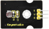
- Photocell sensor, PIR motion sensor and LED. When at night, someone passes by, LED is on; nobody is around, the LED is off.
- There are 1602LCD display, 2 buttons, 1 servo on the board. Press button1 to enter the password(you can set password in the test code), the 1602LCD will show “*”, then press button2 to “ensure”. If the password is correct, the 1602LCD will show “open”, the door will be open. However, if the password is wrong, the “error” pops up , after 2s, “error” will turn into “again” , you can enter password again.
The door will be closed when PIR motion sensor doesn’t detect people around. What’s more, press and hold button2, buzzer will sound, LCD displays “wait”.(If the password is right, the servo will rotate to 180°, otherwise,the servo don’t rotate)
Note: The correct password is ”. - - . - .” which means that short press button1, long press button1, long press button1, short press button1, long press button1, short press button1.
”- ”means long press button1, ”.”means short press button1
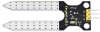
- Insert soil humidity into plant pot, when the soil is too dry, buzzer will alarm and you will get the notification on app.
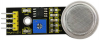
- When the gas sensor detects the gas with high concentration, the buzzer emits a "tick,tick" alarm sound.
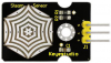
- When steam sensor detects rains, the servo 2 will be activated, the window will be closed automatically, otherwise, the window will be open.


Equipment:

Connection Diagram:

Test Code:
//call the relevant library file
#include <Servo.h>
#include <Wire.h>
#include <LiquidCrystal_I2C.h>
//Set the communication address of I2C to 0x27, display 16 characters every line, two lines in total
LiquidCrystal_I2C mylcd(0x27, 16, 2);

//set ports of two servos to digital 9 and 10
Servo servo_10;
Servo servo_9;

volatile int btn1_num;//set variable btn1_num
volatile int btn2_num;//set variable btn2_num
volatile int button1;//set variable button1
volatile int button2;//set variable button2
String fans_char;//string type variable fans_char
volatile int fans_val;//set variable fans_char
volatile int flag;//set variable flag
volatile int flag2;//set variable flag2
volatile int flag3;//set variable flag3
volatile int gas;//set variable gas
volatile int infrar;//set variable infrar
String led2;//string type variable led2
volatile int light;//set variable light
String pass;//string type variable pass
String passwd;//string type variable passwd

String servo1;//string type variable servo1
volatile int servo1_angle;//set variable light
String servo2;//string type variable servo2
volatile int servo2_angle;//set variable servo2_angle

volatile int soil;//set variable soil
volatile int val;//set variable val
volatile int value_led2;//set variable value_led2
volatile int water;//set variable water

int length;
int tonepin = 3; //set the signal end of passive buzzer to digital 3
//define name of every sound frequency
#define D0 -1
#define D1 262
#define D2 293
#define D3 329
#define D4 349
#define D5 392
#define D6 440
#define D7 494
#define M1 523
#define M2 586
#define M3 658
#define M4 697
#define M5 783
#define M6 879
#define M7 987
#define H1 1045
#define H2 1171
#define H3 1316
#define H4 1393
#define H5 1563
#define H6 1755
#define H7 1971

#define WHOLE 1
#define HALF 0.5
#define QUARTER 0.25
#define EIGHTH 0.25
#define SIXTEENTH 0.625

//set sound play frequency
int tune[] =
{
  M3, M3, M4, M5,
  M5, M4, M3, M2,
  M1, M1, M2, M3,
  M3, M2, M2,
  M3, M3, M4, M5,
  M5, M4, M3, M2,
  M1, M1, M2, M3,
  M2, M1, M1,
  M2, M2, M3, M1,
  M2, M3, M4, M3, M1,
  M2, M3, M4, M3, M2,
  M1, M2, D5, D0,
  M3, M3, M4, M5,
  M5, M4, M3, M4, M2,
  M1, M1, M2, M3,
  M2, M1, M1
};

//set music beat
float durt[] =
{
  1, 1, 1, 1,
  1, 1, 1, 1,
  1, 1, 1, 1,
  1 + 0.5, 0.5, 1 + 1,
  1, 1, 1, 1,
  1, 1, 1, 1,
  1, 1, 1, 1,
  1 + 0.5, 0.5, 1 + 1,
  1, 1, 1, 1,
  1, 0.5, 0.5, 1, 1,
  1, 0.5, 0.5, 1, 1,
  1, 1, 1, 1,
  1, 1, 1, 1,
  1, 1, 1, 0.5, 0.5,
  1, 1, 1, 1,
  1 + 0.5, 0.5, 1 + 1,
};


void setup() {
  Serial.begin(9600);//set baud rate to 9600

  mylcd.init();
  mylcd.backlight();//initialize LCD
  //LCD shows "passcord:" at first row and column
  mylcd.setCursor(1 - 1, 1 - 1);
  mylcd.print("passcord:");

  servo_9.attach(9);//make servo connect to digital 9
  servo_10.attach(10);//make servo connect to digital 10
  servo_9.write(0);//set servo connected digital 9 to 0°
  servo_10.write(0);//set servo connected digital 10 to 0°
  delay(300);

  pinMode(7, OUTPUT);//set digital 7 to output
  pinMode(6, OUTPUT);//set digital 6 to output
  digitalWrite(7, HIGH); //set digital 7 to high level
  digitalWrite(6, HIGH); //set digital 6 to high level

  pinMode(4, INPUT);//set digital 4 to input
  pinMode(8, INPUT);//set digital 8 to input
  pinMode(2, INPUT);//set digital 2 to input
  pinMode(3, OUTPUT);//set digital 3 to output
  pinMode(A0, INPUT);//set A0 to input
  pinMode(A1, INPUT);//set A1 to input
  pinMode(13, OUTPUT);//set digital 13 to input
  pinMode(A3, INPUT);//set A3 to input
  pinMode(A2, INPUT);//set A2 to input

  pinMode(12, OUTPUT);//set digital 12 to output
  pinMode(5, OUTPUT);//set digital 5 to output
  pinMode(3, OUTPUT);//set digital 3 to output
  length = sizeof(tune) / sizeof(tune[0]); //set the value of length
}

void loop() {
  auto_sensor();
  if (Serial.available() > 0) //serial reads the characters
  {
    val = Serial.read();//set val to character read by serial    Serial.println(val);//output val character in new lines
    pwm_control();
  }
  switch (val) {
    case 'a'://if val is character 'a',program will circulate
      digitalWrite(13, HIGH); //set digital 13 to high level,LED 	lights up
      break;//exit loop
    case 'b'://if val is character 'b',program will circulate
      digitalWrite(13, LOW); //Set digital 13 to low level, LED is off
      break;//exit loop
    case 'c'://if val is character 'c',program will circulate
      digitalWrite(12, HIGH); //set digital 12 to high level,NO of relay is connected to COM
      break;//exit loop
    case 'd'://if val is character 'd',program will circulate
      digitalWrite(12, LOW); //set digital 12 to low level,NO of relay is disconnected to COM

      break;//exit loop
    case 'e'://if val is character 'e',program will circulate
      music1();//play birthday song
      break;//exit loop
    case 'f'://if val is character 'f',program will circulate
      music2();//play ode to joy song
      break;//exit loop
    case 'g'://if val is character 'g',program will circulate
      noTone(3);//set digital 3 to stop playing music
      break;//exit loop
    case 'h'://if val is character 'h',program will circulate
      Serial.println(light);//output the value of variable light in new lines
      delay(100);
      break;//exit loop
    case 'i'://if val is character 'i',program will circulate
      Serial.println(gas);//output the value of variable gas in new lines
      delay(100);
      break;//exit loop
    case 'j'://if val is character 'j',program will circulate
      Serial.println(soil);//output the value of variable soil in new lines
      delay(100);
      break;//exit loop
    case 'k'://if val is character 'k',program will circulate
      Serial.println(water);//output the value of variable water in new lines
      delay(100);
      break;//exit loop
    case 'l'://if val is character 'l',program will circulate
      servo_9.write(180);//set servo connected to digital 9 to 180°
      delay(500);
      break;//exit loop
    case 'm'://if val is character 'm',program will circulate
      servo_9.write(0);;//set servo connected to digital 9 to 0°
      delay(500);
      break;//exit loop
    case 'n'://if val is character 'n',program will circulate
      servo_10.write(180);//set servo connected to digital 10 to 180°
      delay(500);
      break;//exit loop
    case 'o'://if val is character 'o',program will circulate
      servo_10.write(0);//set servo connected to digital 10 to 0°
      delay(500);
      break;//exit loop
    case 'p'://if val is character 'p',program will circulate
      digitalWrite(5, HIGH); //set digital 5 to high level, LED is on
      break;//exit loop
    case 'q'://if val is character 'q',program will circulate
      digitalWrite(5, LOW); // set digital 5 to low level, LED is off
      break;//exit loop
    case 'r'://if val is character 'r',program will circulate
      digitalWrite(7, LOW);
      digitalWrite(6, HIGH); //fan rotates anticlockwise at the fastest speed
      break;//exit loop
    case 's'://if val is character 's',program will circulate
      digitalWrite(7, LOW);
      digitalWrite(6, LOW); //fan stops rotating
      break;//exit loop
  }
}

////////////////////////set birthday song//////////////////////////////////
void birthday()
{
  tone(3, 294); //digital 3 outputs 294HZ sound
  delay(250);//delay in 250ms
  tone(3, 440);
  delay(250);
  tone(3, 392);
  delay(250);
  tone(3, 532);
  delay(250);
  tone(3, 494);
  delay(500);
  tone(3, 392);
  delay(250);
  tone(3, 440);
  delay(250);
  tone(3, 392);
  delay(250);
  tone(3, 587);
  delay(250);
  tone(3, 532);
  delay(500);
  tone(3, 392);
  delay(250);
  tone(3, 784);
  delay(250);
  tone(3, 659);
  delay(250);
  tone(3, 532);
  delay(250);
  tone(3, 494);
  delay(250);
  tone(3, 440);
  delay(250);
  tone(3, 698);
  delay(375);
  tone(3, 659);
  delay(250);
  tone(3, 532);
  delay(250);
  tone(3, 587);
  delay(250);
  tone(3, 532);
  delay(500);
}


//detect gas
void auto_sensor() {
  gas = analogRead(A0);//assign the analog value of A0 to gas
  if (gas > 700) {
//if variable gas>700
    flag = 1;//set variable flag to 1
    while (flag == 1)
      //if flag is 1, program will circulate
    {
      Serial.println("danger");//output "danger" in new lines
      tone(3, 440);
      delay(125);
      delay(100);
      noTone(3);
      delay(100);
      tone(3, 440);
      delay(125);
      delay(100);
      noTone(3);
      delay(300);
      gas = analogRead(A0);//gas analog the value of A0 to gas
      if (gas < 100)  //if variable gas is less than 100
      {
        flag = 0;//set variable flag to 0
        break;//exit loop exist to loop
      }
    }

  } else
    //otherwise
  {
    noTone(3);// digital 3 stops playing music
  }
  light = analogRead(A1);////Assign the analog value of A1 to light
  if (light < 300)//if variable light is less than 300
  {
    infrar = digitalRead(2);//assign the value of digital 2 to infrar
    Serial.println(infrar);//output the value of variable infrar in new lines
    if (infrar == 1)
      // if variable infra is 1
    {
      digitalWrite(13, HIGH); //set digital 13 to high level, LED is on
    } else//Otherwise
    {
      digitalWrite(13, LOW); //set digital 13 to low level, LED is off
    }

  }
  water = analogRead(A3);//assign the analog value of A3 to variable water
  if (water > 800)
    // if variable water is larger than 800
  {
    flag2 = 1;//if variable flag 2 to 1
    while (flag2 == 1)
      // if flag2 is 1, program will circulate
    {
      Serial.println("rain");//output "rain" in new lines
      servo_10.write(180);// set the servo connected to digital 10 to 180°
      delay(300);//delay in 300ms
      delay(100);
      water = analogRead(A3);;//assign the analog value of A3 to variable water
      if (water < 30)// if variable water is less than 30
      {
        flag2 = 0;// set flag2 to 0
        break;//exit loop
      }
    }

  } else//Otherwise
  {
    if (val != 'u' && val != 'n')
      //if val is not equivalent 'u' either 'n'
    {
      servo_10.write(0);//set servo connected to digital 10 to 0°
      delay(10);

    }

  }
  soil = analogRead(A2);//assign the analog value of A2 to variable soil
  if (soil > 50)
    // if variable soil is greater than 50
  {
    flag3 = 1;//set flag3 to 1
    while (flag3 == 1)
      //If set flag3 to 1, program will circulate
    {
      Serial.println("hydropenia ");//output "hydropenia " in new lines
      tone(3, 440);
      delay(125);
      delay(100);
      noTone(3);
      delay(100);
      tone(3, 440);
      delay(125);
      delay(100);
      noTone(3);//digital 3 stops playing sound
      delay(300);
      soil = analogRead(A2);//Assign the analog value of A2 to variable soil
      if (soil < 10)//If variable soil<10
      {
        flag3 = 0;//set flag3 to 0
        break;//exit loop
      }
    }

  } else//Otherwise
  {
    noTone(3);//set digital 3 to stop playing music
  }
  door();//run subroutine
}

void door() {
  button1 = digitalRead(4);// assign the value of digital 4 to button1
  button2 = digitalRead(8);//assign the value of digital 8 to button2


  if (button1 == 0)//if variablebutton1 is 0
  {
    delay(10);//delay in 10ms
    while (button1 == 0) //if variablebutton1 is 0,program will circulate
    {
      button1 = digitalRead(4);// assign the value of digital 4 to button1
      btn1_num = btn1_num + 1;//variable btn1_num plus 1
      delay(100);// delay in 100ms
    }

  }
  if (btn1_num >= 1 && btn1_num < 5) //1≤if variablebtn1_num<5
  {
    Serial.print(".");
    Serial.print("");
    passwd = String(passwd) + String(".");//set passwd
pass = String(pass) + String(".");//set pass
    //LCD shows pass at the first row and column
    mylcd.setCursor(1 - 1, 2 - 1);
    mylcd.print(pass);
  }
  if (btn1_num >= 5)
    //if variablebtn1_num ≥5
  {
    Serial.print("-");
    passwd = String(passwd) + String("-");//Set passwd
    pass = String(pass) + String("-");//set pass
    //LCD shows pass at the first row and column
    mylcd.setCursor(1 - 1, 2 - 1);
    mylcd.print(pass);

  }
  if (button2 == 0) //if variablebutton2 is 0
  {
    delay(10);
    if (button2 == 0)//if variablebutton2 is 0
    {
      if (passwd == ".--.-.")//if passwd is ".--.-."
      {
        mylcd.clear();//clear LCD screen
        //LCD shows "open!" at first character on second row
        mylcd.setCursor(1 - 1, 2 - 1);
        mylcd.print("open!");
        servo_9.write(100);//set servo connected to digital 9 to 100°
        delay(300);
        delay(5000);
        passwd = "";
        pass = "";
        mylcd.clear();//clear LCD screen
        //LCD shows "password:"at first character on first row
        mylcd.setCursor(1 - 1, 1 - 1);
        mylcd.print("password:");

      } else //Otherwise
      {
        mylcd.clear();//clear LCD screen
        //LCD shows "error!"at first character on first row
        mylcd.setCursor(1 - 1, 1 - 1);
        mylcd.print("error!");
        passwd = "";
        pass = "";
        delay(2000);
        //LCD shows "again" at first character on first row
        mylcd.setCursor(1 - 1, 1 - 1);
        mylcd.print("again");
      }
    }
  }
  infrar = digitalRead(2);//assign the value of digital 2 to infrar
  if (infrar == 0 && (val != 'l' && val != 't'))
    //if variable infrar is 0 and val is not 'l' either 't'
  {
    servo_9.write(0);//set servo connected to digital 9 to 0°
    delay(50);
  }
  if (button2 == 0)//if variablebutton2 is 0
  {
    delay(10);
    while (button2 == 0) //if variablebutton2 is 0,program will circulate
    {
      button2 = digitalRead(8);//assign the value of digital 8 to button2
      btn2_num = btn2_num + 1;//variable btn2_num plus 1
      delay(100);
      if (btn2_num >= 15)//if variablebtn2_num ≥15
      {
        tone(3, 532);
        delay(125);
        mylcd.clear();//clear LCD screen
        //LCD shows "password:" at the first character on first row
        mylcd.setCursor(1 - 1, 1 - 1);
        mylcd.print("password:");
        //LCD shows "wait" at the first character on first row
        mylcd.setCursor(1 - 1, 1 - 1);
        mylcd.print("wait");
      } else//Otherwise
      {
        noTone(3);//digital 3 stops playing music
      }
    }

  }
  btn1_num = 0;//set btn1_num to 0
  btn2_num = 0;//set btn2_num to 0
}

// Birthday song
void music1() {
  birthday();
}
//Ode to joy
void music2() {
  Ode_to_Joy();
}
void Ode_to_Joy()//play Ode to joy song
{
  for (int x = 0; x < length; x++)
  {
    tone(tonepin, tune[x]);
    delay(300 * durt[x]);
  }
}

//PWM control
void pwm_control() {
  switch (val)
  {
    case 't'://if val is 't',program will circulate
      servo1 = Serial.readStringUntil('#');
      servo1_angle = String(servo1).toInt();
      servo_9.write(servo1_angle);//set the angle of servo connected to digital 9 to servo1_angle
      delay(300);
      break;//exit loop
    case 'u'://if val is 'u',program will circulate
      servo2 = Serial.readStringUntil('#');
      servo2_angle = String(servo2).toInt();
      servo_10.write(servo2_angle);//set the angle of servo connected to digital 10 to servo2_angle
      delay(300);
      break;//exit loop
    case 'v'://if val is 'v',program will circulate
      led2 = Serial.readStringUntil('#');
      value_led2 = String(led2).toInt();
      analogWrite(5, value_led2); //PWM value of digital 5 is value_led2
      break;//exit loop
    case 'w'://if val is 'w',program will circulate
      fans_char = Serial.readStringUntil('#');
      fans_val = String(fans_char).toInt();
      digitalWrite(7, LOW);
      analogWrite(6, fans_val); //set PWM value of digital 6 to fans_val,the larger the value, the faster the fan
      break;//exit loop
  }
}
Upload the code and see the result!
Note: Remove the Bluetooth module please, when uploading the test code. Otherwise, the program will fail to upload. Connect the Bluetooth and Bluetooth module to pair after uploading the test code.
Test Result
Upload the test code, stack expansion board on PLUS control board, and power on. After pairing and connecting Bluetooth successfully, we can control the smart home through app.
Related Resources
- Wiki page: https://wiki.keyestudio.com/Main_Page
- Official website: https://keyestudio.com/
- Kidsbits website: https://wiki.kidsbits.cc/
More details about video, product file, software downlod, refer to the following link please
Buy From
- [ Official website: ]
- [ Shop on aliexpress store]