KS0349 Keyestudio 48 in 1 Sensor Kit
Description
This sensor kit contains 48 kinds of commonly used sensor modules in playing the microcontroller, such as active buzzer module, 5V relay module, temperature and humidity module and so on. It is compatible for various microcontrollers and Raspberry Pi. At the same time, we also provide some detailed projects for each sensor based on development board, including wiring method, test code, etc. It can help you have further understanding of those sensor modules and can apply them to interactive projects. Note that in the following projects, the main board and other wires are not included in this kit. You need to prepare them by yourself.
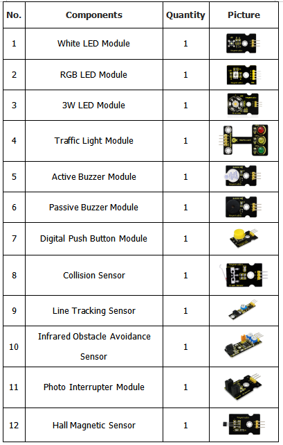
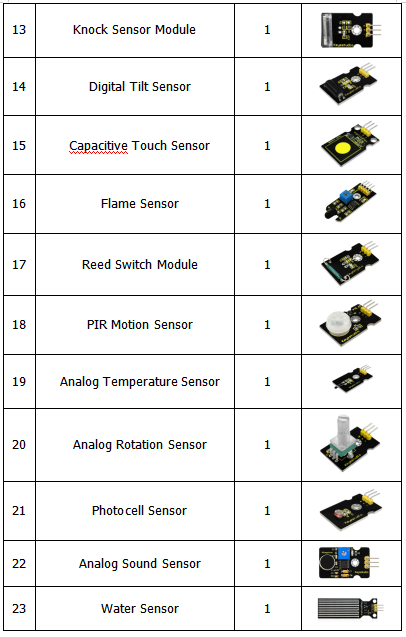
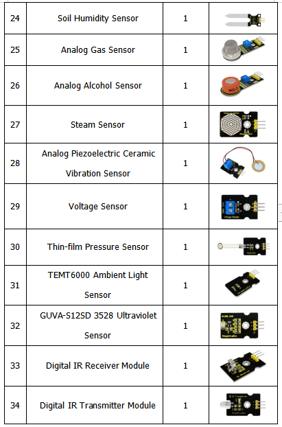
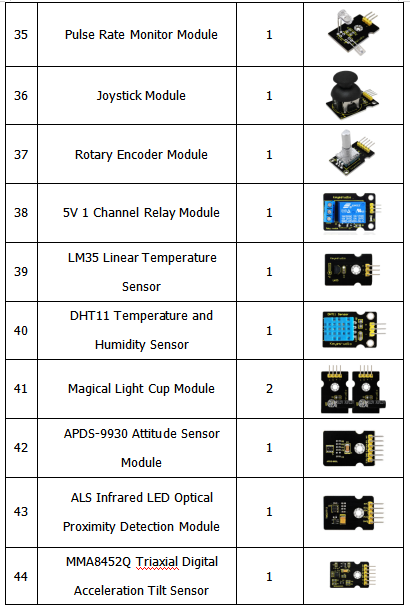
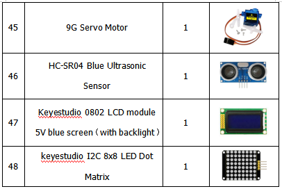
Component List
Install Arduino IDE and Driver
Download software
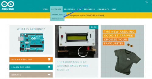
When we get control board, we need to download Arduino IDE and driver firstly. You could download Arduino IDE from the official website: https://www.arduino.cc/, click the SOFTWARE on the browse bar, click “DOWNLOADS” to enter download page, as shown below:
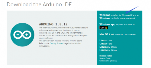
There are various versions for Arduino, just download a suitable version for your system, we will take WINDOWS system as an example to show you how to download and install.
There are two versions for WINDOWS system, one is installed version, another one is download version, you just need to download file to computer directly and unzip it. These two versions can be used normally. Choose one and download on your computer.
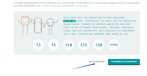
You just need to click JUST DOWNLOAD, then click the downloaded file to install it. And when the ZIP file is downloaded, you can directly unzip and start it.
We need to know keyestudio V4.0 development board, as a core of this smart car.
(1)Keyestudio V4.0 Development Board
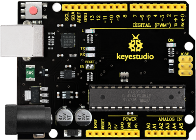
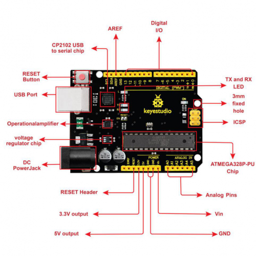
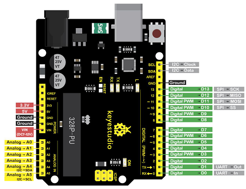
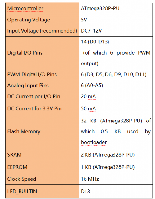
keyestudio V4.0 development board is an Arduino uno-compatible board, which is based on ATmega328P MCU, and with a cp2102 Chip as a UART-to-USB converter.
It has 14 digital input/output pins (of which 6 can be used as PWM outputs), 6 analog inputs, a 16 MHz quartz crystal, a USB connection, a power jack, 2 ICSP headers and a reset button.
It contains everything needed to support the microcontroller; simply connect it to a computer with a USB cable or power it via an external DC power jack (DC 7-12V) or via female headers Vin/ GND(DC 7-12V) to get started.
Install other visions of driver
If your development board is Arduino board, install the driver as follows:
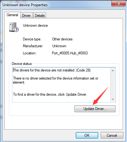
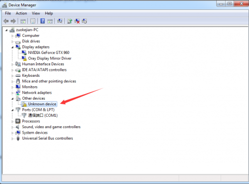
Step 1: Plug in the development board, click Computer----- Properties----- Device Manager, you could see the unknown device is shown.
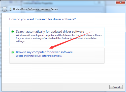
Step 3: click“browse my computer for updated driver software”
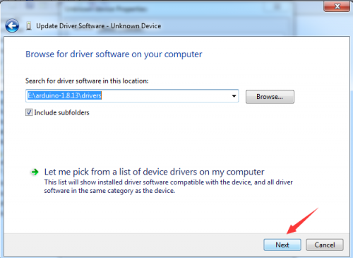
Step 4: find out the folder where the ARDUINO software is installed, click drivers folder and tap“Next”
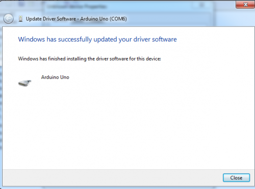
Step 5: the driver is installed successfully.
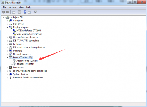
The device manager shows the serial port of Arduino.
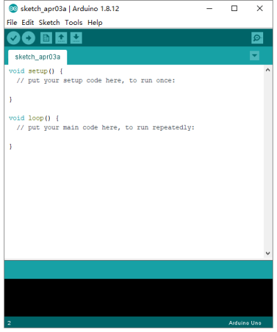
Arduino IDE Setting
To avoid the errors when uploading the program to the board, you need to select the correct Arduino board that matches the board connected to your computer.
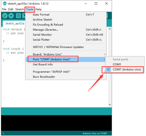
Then come back to the Arduino software, you should click Tools→Board, select the board. (as shown below)
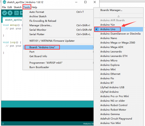
Then select the correct COM port (you can see the corresponding COM port after the driver is successfully installed)
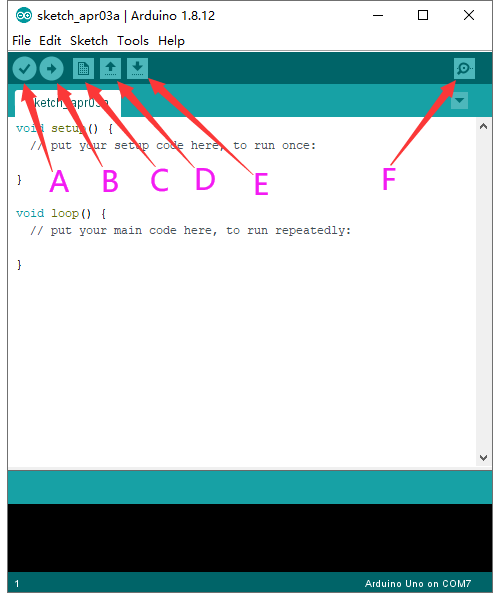
Before uploading the program to the board, let’s demonstrate the function of each symbol in the Arduino IDE toolbar.
A- Used to verify whether there is any compiling mistakes or not.
B- Used to upload the sketch to your Arduino board.
C- Used to create shortcut window of a new sketch.
D- Used to directly open an example sketch.
E- Used to save the sketch.
F- Used to send the serial data received from board to the serial monitor.
Start your first program
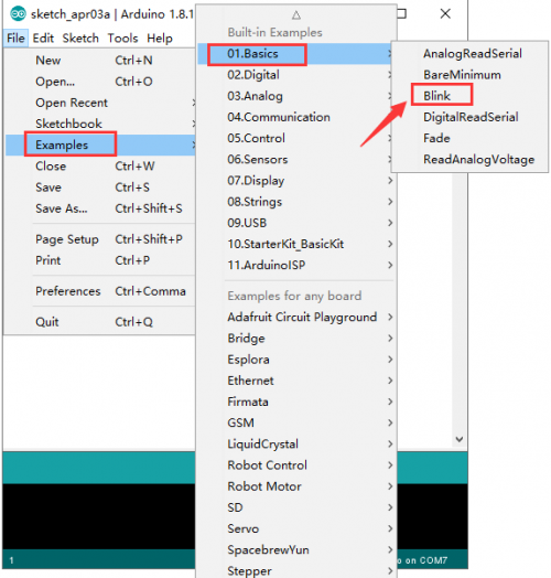
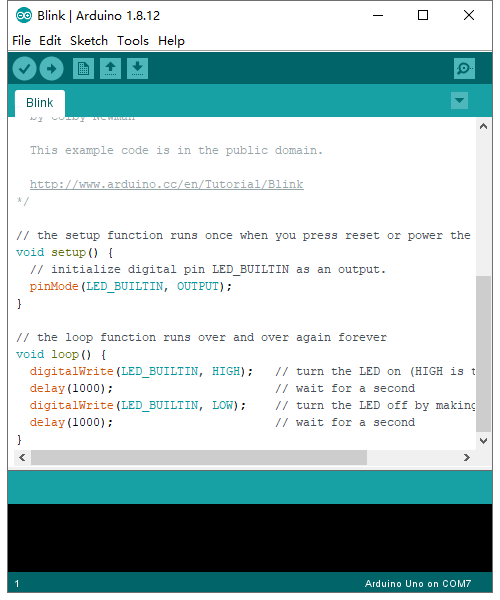
Open the file to select Example, choose BLINK from BASIC, as shown below:
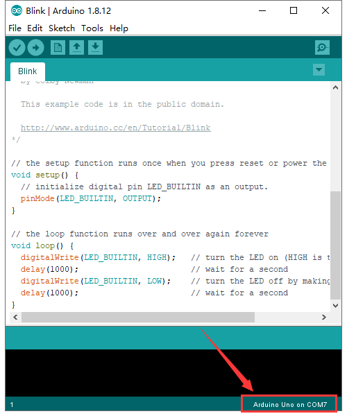
Set board and COM port, the corresponding board and COM port are shown on the lower right of IDE.
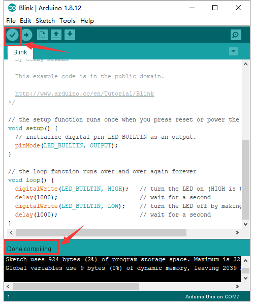
Click ![]() to start compiling the program, check errors.
to start compiling the program, check errors.
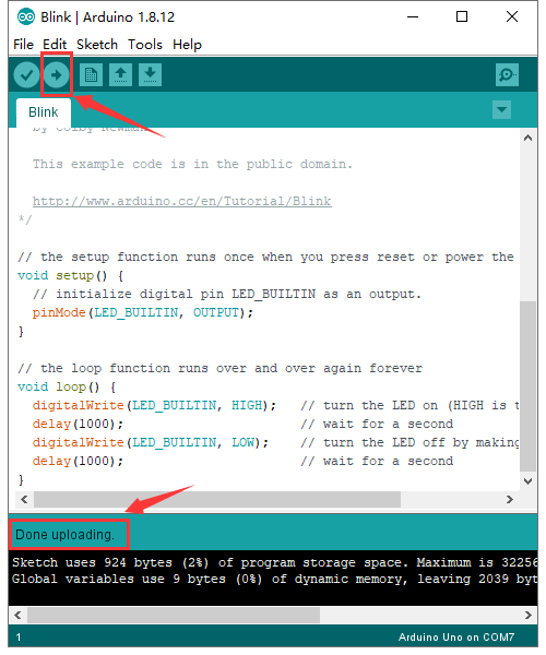
Click ![]() to upload the program, upload successfully.
to upload the program, upload successfully.
Upload the program successfully, the onboard LED lights on for 1s, lights off for 1s. Congratulation, you finish the first program.
