KS0444 Keyestudio 6812 Full-color RGB LED Ring Shield for Micro:bit
Overview
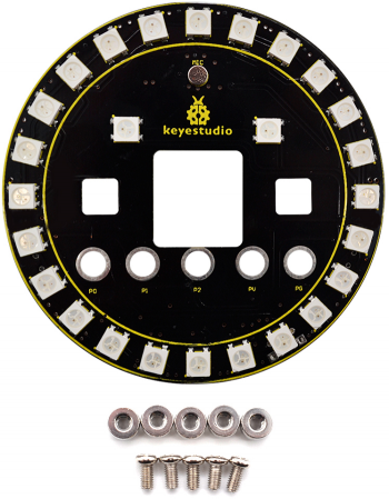
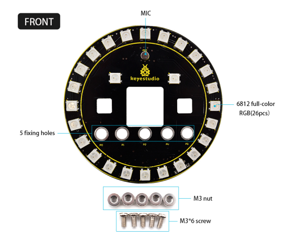
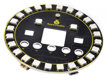
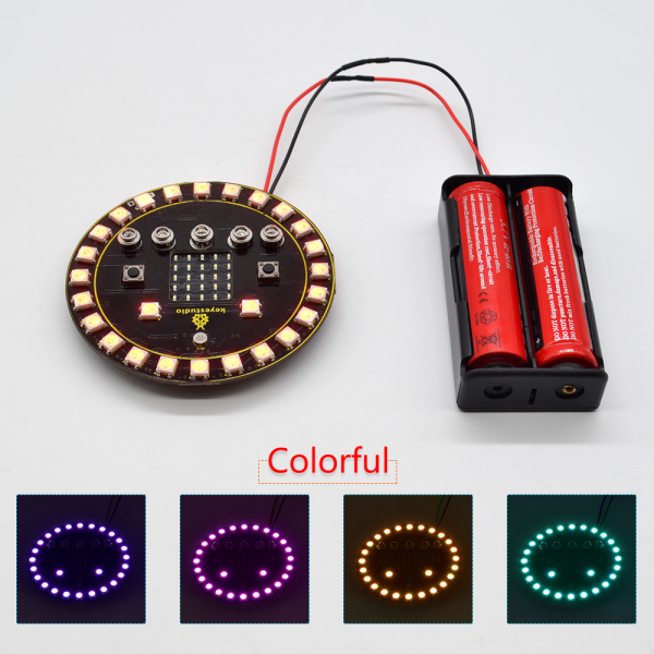
Keyestudio 6812 Full-color RGB LED Ring Shield is fully compatible for Micro:bit development board. It integrates 26 6812 Full-color RGB LEDS, a microphone and a passive buzzer.
The RGB ring shield is super cool; and comes with 5 M3 fixing holes (wiring terminal), so easy to mount or connect the micro:bit main board to the shield using included 5 screws and 5 nuts.
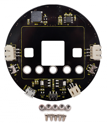
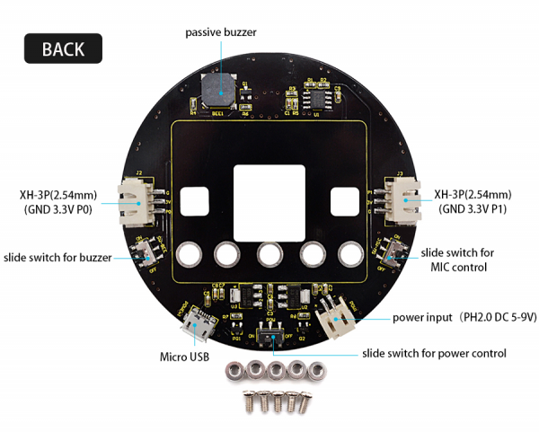
For power supply, you can use built-in micro USB port or PH2.0-2P connector (DC 5-9V). The shield comes with a slide switch for power control.
The shield’s P0 is for passive buzzer control, which depends on a slide switch. When turn the slide switch to OFF position, passive buzzer is available; turn to ON position, the P0 can access to external devices via XH-3P socket.
The P1 is connected to microphone, also depending on a slide switch. When turn the slide switch to OFF position, MIC is available; turn to ON position, the P1 can access to external devices via XH-3P socket.
Technical Details
- Voltage input: DC 5-9V
- Operating voltage: DC 3.3V
- Operating current: 350mA
- Maximum power: 1.5W
- Operating temperature range: -20℃~+75℃
- Dimensions: diameter 80mm
- Weight: 26g
- Environmental properties: ROHS
- Comes with 5 M3 nuts, 5 M3*6 screws
PINOUTS
Connection
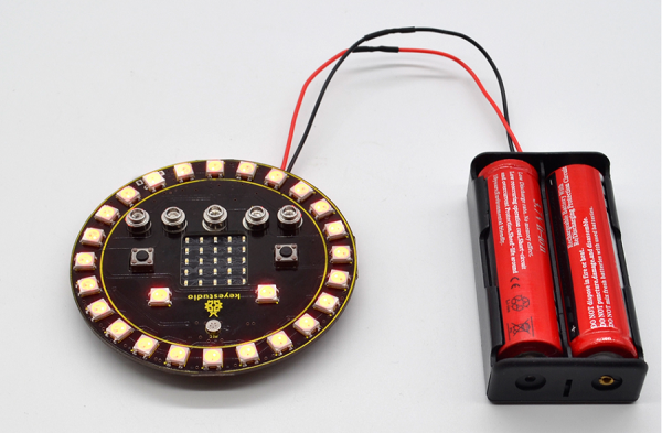
Tighten the micro:bit main board to the RGB shield using 5 screws and 5 nuts.
Source Code
Connect the 6812 Full-color RGB LED Ring Shield for micro:bit to the computer using a micro USB cable.
Copy the hex file to your micro:bit just like copying a file to a USB drive.
On package find the microbit-KS0444 file, you can right click and choose "Send To→MICROBIT."
Test Result
Done uploading the code, turn the slide switch for power to ON position; turn slide switch for passive buzzer to OFF position, and slide switch for MIC to ON position.
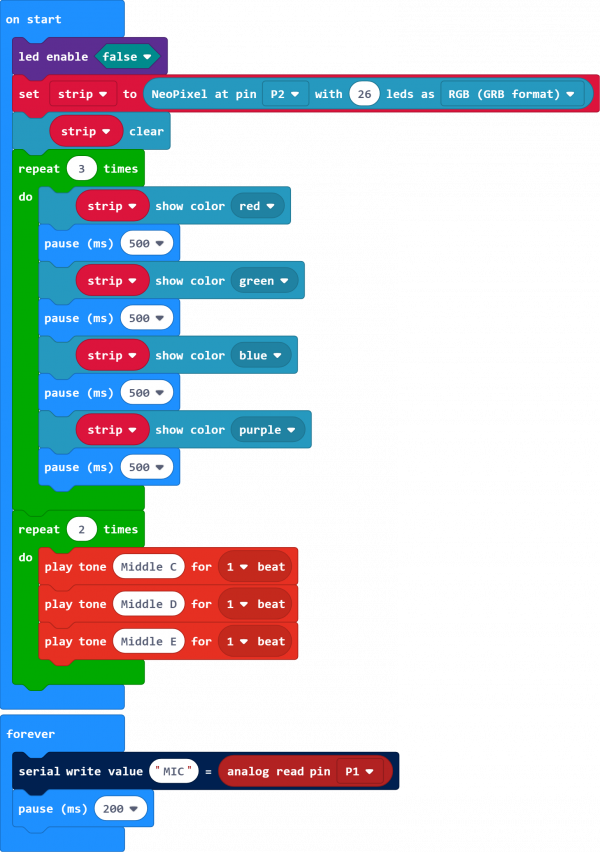
The 26 RGB LEDs on the shield will circularly turn on red, green, blue and purple three times. The passive buzzer makes a beat mediant C, mediant D, mediant E twice, for loop.
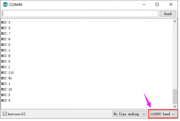
Open the serial monitor and set the baud rate to 115200, the monitor window will print out the analog value of sound measured by MIC.
The louder the sound, the larger the analog value. As shown below.
Resources
- Download relevant datasheet and code:
https://fs.keyestudio.com/KS0444
- BBC micro:bit website
- Micro:bit MakeCode Block Editor
- Meet micro:bit starter programming
- BBC micro:bit Features Guide
- BBC micro:bit Safety Warnings
- BBC micro:bit Quick Start Guide
- BBC micro:bit Pins
