KS0487 Keyestudio 37 in 1 Sensor Kit upgrade v3.0: Difference between revisions
Keyestudio (talk | contribs) No edit summary |
Keyestudio (talk | contribs) No edit summary |
||
| Line 18: | Line 18: | ||
| Traffic light module || [[image:0487-2.png|thumb|100px|]] | | Traffic light module || [[image:0487-2.png|thumb|100px|]] | ||
|- | |- | ||
| SMD RGB || | | SMD RGB || [[image:0487-3.png|thumb|100px|]] | ||
|- | |- | ||
| 4-digit tube module || | | 4-digit tube module || [[image: 0487-4.png|thumb|100px|]] | ||
|- | |- | ||
| Active buzzer module || | | Active buzzer module || [[image: 0487-5.png|thumb|100px|]] | ||
|- | |- | ||
| Passive buzzer module || | | Passive buzzer module || [[image: 0487-6.png|thumb|100px|]] | ||
|- | |- | ||
|Vibration motor module || | |Vibration motor module || [[image: 0487-7.png|thumb|100px|]] | ||
|- | |- | ||
| button Module || | | button Module || [[image: 0487-8.png|thumb|100px|]] | ||
|- | |- | ||
|Touch module || | |Touch module || [[image: 0487-9.png|thumb|100px|]] | ||
|- | |- | ||
| Knock module || | | Knock module || [[image: 0487-10.png|thumb|100px|]] | ||
|- | |- | ||
| Tilt module || | | Tilt module || [[image:0487-11.png|thumb|100px|]] | ||
|- | |- | ||
| IR Switch || | | IR Switch || [[image:0487-12.png|thumb|100px|]] | ||
|- | |- | ||
| reed switch || | | reed switch || [[image:0487-13.png |thumb|100px|]] | ||
|- | |- | ||
| Hall transducer || | | Hall transducer || [[image:0487-14.png |thumb|100px|]] | ||
|- | |- | ||
| Crash Sensor || | | Crash Sensor || [[image:0487-15.png |thumb|100px|]] | ||
|- | |- | ||
| Line tracking || | | Line tracking || [[image:0487-16.png |thumb|100px|]] | ||
|- | |- | ||
| obstacle avoidance || | | obstacle avoidance || [[image:0487-17.png |thumb|100px|]] | ||
|- | |- | ||
| Photo resistor|| | | Photo resistor|| 0487-18.png | ||
|- | |- | ||
| Simulated temperature || | | Simulated temperature || 0487-19.png | ||
|- | |- | ||
| Adjustable potentiometer module || | | Adjustable potentiometer module || 0487-20.png | ||
|- | |- | ||
| Sound module || | | Sound module || 0487-21.png | ||
|- | |- | ||
| Flame || | | Flame || 0487-22.png | ||
|- | |- | ||
| Flame || | | Flame || 0487-23.png | ||
|- | |- | ||
| Soil || | | Soil || 0487-24.png | ||
|- | |- | ||
| Steam sensor || | | Steam sensor || 0487-25.png | ||
|- | |- | ||
| Ceramic vibration sensor || | | Ceramic vibration sensor || 0487-26.png | ||
|- | |- | ||
| Voltage detection module || | | Voltage detection module || 0487-27.png | ||
|- | |- | ||
| IR receiver || | | IR receiver || 0487-28.png | ||
|- | |- | ||
| IR transmitter || | | IR transmitter || 0487-29.png | ||
|- | |- | ||
| Joystick module || | | Joystick module || 0487-30.png | ||
|- | |- | ||
| 5V single-channel relay || | | 5V single-channel relay || 0487-31.png | ||
|- | |- | ||
| Rotary encoder module || | | Rotary encoder module || 0487-32.png | ||
|- | |- | ||
| finger-measuring heartbeat module || | | finger-measuring heartbeat module || 0487-33.png | ||
|- | |- | ||
| LM35 Temperature || 示例 | | LM35 Temperature || 示例 | ||
Revision as of 17:38, 18 November 2019
Description
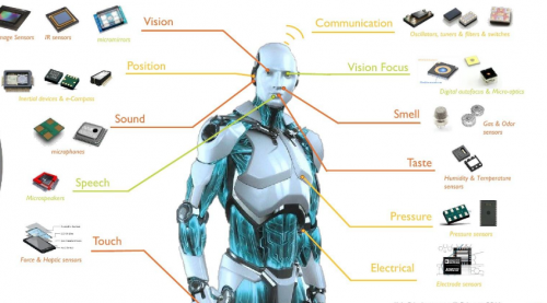
This is an era of artificial intelligence. Artificial intelligence is everywhere and has been integrated into our lives, especially for all kinds of robots. To understand the robot, we should understand the control system of the robot. The microcontroller we learn is equivalent to the brain of the robot. The various sensors installed on the robot are their eyes, noses, mouths, ears and so on. To make it easier for beginners to understand these principles, Keyestudio has released the 3.0 version of the sensor kit, which includes digital and analog sensors as well as special modules such as ultrasound, digital tubes, temperature and humidity. For each module, there is a clear connection diagram and sample code. So it's easy to operate even you are a newbie.
The sample code of this sensor suite is based on ARDUINO because it is open source and easy to use. If you're good at it, you can also apply this kit to other development platforms such as 51, STM32, Raspberries Pi, micro:bit, the working principle of those platforms is almost same.
Now let's enter the world of robotic sensors and learn together!
Component List
| Straw Hat Led | |
|---|---|
| Traffic light module | |
| SMD RGB | |
| 4-digit tube module | |
| Active buzzer module | |
| Passive buzzer module | |
| Vibration motor module | |
| button Module | |
| Touch module | |
| Knock module | |
| Tilt module | |
| IR Switch | |
| reed switch | |
| Hall transducer | |
| Crash Sensor | |
| Line tracking | |
| obstacle avoidance | |
| Photo resistor | 0487-18.png |
| Simulated temperature | 0487-19.png |
| Adjustable potentiometer module | 0487-20.png |
| Sound module | 0487-21.png |
| Flame | 0487-22.png |
| Flame | 0487-23.png |
| Soil | 0487-24.png |
| Steam sensor | 0487-25.png |
| Ceramic vibration sensor | 0487-26.png |
| Voltage detection module | 0487-27.png |
| IR receiver | 0487-28.png |
| IR transmitter | 0487-29.png |
| Joystick module | 0487-30.png |
| 5V single-channel relay | 0487-31.png |
| Rotary encoder module | 0487-32.png |
| finger-measuring heartbeat module | 0487-33.png |
| LM35 Temperature | 示例 |
| Temperature and humidity | 示例 |
| ultrasound | 示例 |
| IR Sensor | 示例 |
Project
Project 1: White LED
Description
This white LED light module is ideal for Arduino starters. It can be easily connected to IO/Sensor shield. It enables interaction with light-related works.
Note: You can choose other LED modules to emit different color like yellow, red, green and blue.
Specification
- White LED module
- Type: Digital
- PH2.54 socket
- Size: 30*20mm
- Weight: 3g
Connection Diagram
First, you need to prepare the following parts before connection:
UNO board*1
White LED module *1
USB Cable*1
Jumper wire*3
Connect the S pin of module to Digital 3 of UNO board, connect the negative pin to GND port, positive pin to 5V port.

Sample Code
Copy and paste the below code to Arduino software. int led = 3; void setup() {
pinMode(led, OUTPUT); //Set Pin3 as output
} void loop() { digitalWrite(led, HIGH); //Turn on led
         delay(2000);
         digitalWrite(led, LOW);    //Turn off led
         delay(2000);
}
Example Result
Done wiring and powered up, upload well the code, you will see the LED module emit the white light.

=
Description
This is a full-color LED module, which contains 3 basic colors-red, green and blue. They can be seen as separate LED lights. After programming, you can turn them on and off by sequence or can also use PWM analog output to mix three colors to generate different colors.
Specification
- Color: red, green and blue
- Brightness: High
- Voltage: 5V
- Input: digital level
- Size: 30*20mm
- Weight: 3g
Connection Diagram
First, you need to prepare the following parts before connection:
- UNO Board*1
- RGB LED module *1
- USB Cable*1
- Jumper Wire*4
Connect the V pin of module to 5V port of UNO board, connect the B pin to Digital 9, R pin to Digital 10, G pin to Digital 11 .

Sample Code
Copy and paste the below code to Arduino software. int redpin = 11; //select the pin for the red LED int bluepin =10; // select the pin for the blue LED int greenpin =9;// select the pin for the green LED int val; void setup() {
 pinMode(redpin, OUTPUT);
 pinMode(bluepin, OUTPUT);
 pinMode(greenpin, OUTPUT);
 }
void loop() {for(val=255; val>0; val--)
 {analogWrite(11, val);
  analogWrite(10, 255-val);
  analogWrite(9, 128-val);
  delay(1);
 }
for(val=0; val<255; val++)
 {analogWrite(11, val);
  analogWrite(10, 255-val);
  analogWrite(9, 128-val);
  delay(1);  }
}
Example Result
Done wiring and powered up,upload well the code, you will see the RGB LED module emit shiny colors.

Project 3: Traffic Light
Description
When learning the microcontroller, you may usually use three LEDs, namely red, green and yellow lights to simulate the traffic light blinking via external connection.
This time we specially design this module which is very convenient for wiring, and on the module you can see the red, yellow and green LED. This module is fully compatible with Arduino microcontroller and Raspberry Pi system.
Specification
- Working Voltage: 3.3-5v
- Interface Type: digital
- PH2.54 Socket
- Connection Diagram:
- First, you need to prepare the following parts before connection:
- UNO Board*1
- Traffic light module *1
- USB Cable*1
- Jumper Wire*4
Connect the R pin of module to Digital 5 of UNO board, connect the Y pin to Digital 4, G pin to Digital 3, GND pin to ground port.

==
Sample Code ====
Copy and paste the below code to Arduino software.
int redled =5; // initialize digital pin 5.
int yellowled =4; // initialize digital pin 4.
int greenled =3; // initialize digital pin 3.
void setup()
{
pinMode(redled, OUTPUT);// set the pin with red LED as “output”
pinMode(yellowled, OUTPUT); // set the pin with yellow LED as “output”
pinMode(greenled, OUTPUT); // set the pin with green LED as “output”
}
void loop()
{
digitalWrite(greenled, HIGH);//// turn on green LED
delay(5000);// wait 5 seconds
digitalWrite(greenled, LOW); // turn off green LED
for(int i=0;i<3;i++)// blinks for 3 times
{
delay(500);// wait 0.5 seconds
digitalWrite(yellowled, HIGH);// turn on yellow LED
delay(500);// wait 0.5 seconds
digitalWrite(yellowled, LOW);// turn off yellow LED
}
delay(500);// wait 0.5 seconds
digitalWrite(redled, HIGH);// turn on red LED
delay(5000);// wait 5 seconds
digitalWrite(redled, LOW);// turn off red LED
}
Example Result:
Done uploading the code, powered up, three LEDs on the module will automatically simulate the traffic light on and off, circularly.

Project 4: Buzzer Beeping
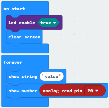
Test code
Test Result
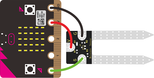
According to wiring diagram, upload test code successfully. After power-on, insert the sensor into soil. The LED dot matrix of micro:bit control board displays the analog value of corresponding soil moisture.
Resources
Download Test Code:
https://1drv.ms/u/s!ArhgRvK6-RyJg2ks7fRZun4VQLEg?e=rGnT7g
Get One Now
- [ Official Website]
- [ Shop on aliexpress ]


