KS0488 Keyestudio 4DOF Robot Arm DIY Kit V2.0 for Arduino: Difference between revisions
Keyestudio (talk | contribs) (Created blank page) |
Keyestudio (talk | contribs) No edit summary |
||
| Line 1: | Line 1: | ||
<br>[[File:0488-7.png|500px|frameless|right]]<br> | |||
== Introduction == | |||
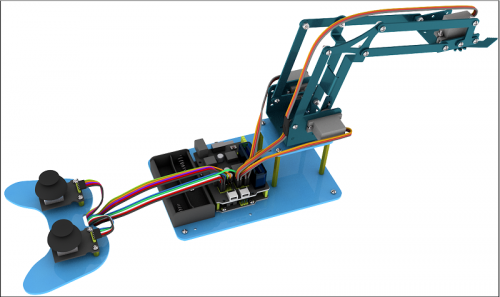
On the Internet, we often see DIY robotic arm complete various actions. Do you want to have one? I believe that you’ll make your own robotic arm by learning our projects.<br> | |||
This kit includes R3 single-chip microcomputer, 2 rocker modules and 4 servos so on. We’ll teach you how to install and debug the robotic arm. | |||
There are 3 ways of controlling metal manipulator in this kit:<br> | |||
1.Use a wired home-made joystick controller (included in the kit)<br> | |||
2.Control via Bluetooth. (HM -10 Bluetooth module included, support Bluetooth 4.0, Android and IOS system). we also provide relevant test code and specially designed APP for robotic arm.<br> | |||
3.Use wireless PS2 joystick (not included in kit) module to control. We only provide relevant test codes.<br> | |||
== Features == | |||
* Detailed installation method. | |||
* Detailed debugging methods, even you’re a beginner. | |||
* 3 methods of controlling: wired joystick control, Bluetooth control, wireless PS2 joystick control. | |||
* Relevant information provided | |||
== Specification == | |||
'''Keyestudio TB6612FNG Motor/Servo Drive Shield:'''<br> | |||
* VIN voltage: VIN = DC 7-15V | |||
* VIN current: 5A | |||
* Size: 73 * 53.34mm | |||
* 2 way 5V outputs: 5V / 3A | |||
* TB6612FNG: VIN input DC 7-15V, average drive current 1.2A, peak current 3.2A. | |||
* PS2 interface: compatible with Sony PS2 receiver, can be plugged directly into the shield. | |||
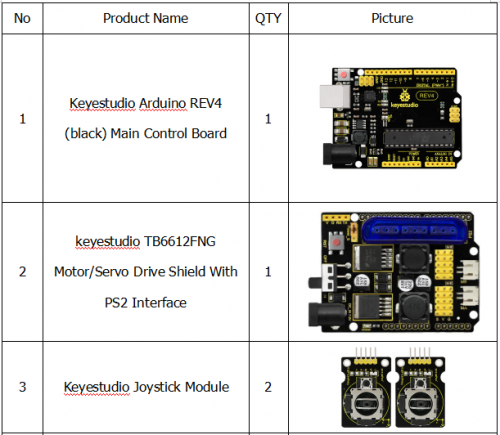
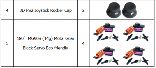
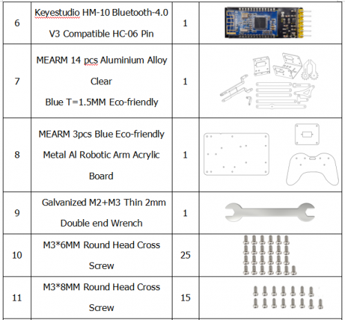
== Component List == | |||
<br>[[File:QQ图片2456.png|500px|frameless|thumb]]<br> | |||
<br>[[File:QQ图片2457.png|500px|frameless|thumb]]<br> | |||
<br>[[File:QQ图片258.png|500px|frameless|thumb]]<br> | |||
<br>[[File:QQ图片259.png|500px|frameless|thumb]]<br> | |||
<br>[[File:QQ图片260.png|500px|frameless|thumb]]<br> | |||
<br>[[File:QQ图片261.png|500px|frameless|thumb]]<br> | |||
<br>[[File:QQ图片262.png|500px|frameless|thumb]]<br> | |||
<br> | |||
== Robot Arm Projects == | |||
'''REV4 Control Board'''<br> | |||
<br> [[File:0488.png|500px|frameless|thumb]] | |||
When it comes to using the UNO R3 as core of our robot, the UNO is the best board to get started with electronics and coding. | |||
If this is your first experience tinkering with the platform, the UNO is the most robust board you can start playing with. | |||
Well, let's at first have a look at this UNO R3 board. | |||
<br> [[File:0488-1.png|500px|frameless|thumb]] | |||
{| width="80%" cellspacing="0" border="1" | |||
|- | |||
| align="center" | [[Image:KS0001 5-1.png|500px|frameless]] | |||
| align="light" | '''ICSP (In-Circuit Serial Programming) Header'''<br> | |||
In most case, ICSP is the AVR,an Arduino micro-program header consisting of MOSI, MISO, SCK, RESET, VCC, and GND. It is often called the SPI (serial peripheral interface) and can be considered an "extension" of the output. In fact, slave the output devices under the SPI bus host.<br> | |||
When connecting to PC, program the firmware to ATMEGA328P-PU. | |||
|- | |||
| align="center" | [[Image:KS0001 5-2.png|500px|frameless]] | |||
| align="light" | '''Power LED Indicator''' | |||
Powering the Arduino, LED on means that your circuit board is correctly powered on. If LED is off, connection is wrong. | |||
|- | |||
| align="center" | [[Image:KS0001 5-3.png|500px|frameless]] | |||
| align="light" | '''Digital I/O''' | |||
Arduino REV4 has 14 digital input/output pins (of which 6 can be used as PWM outputs). These pins can be configured as digital input pin to read the logic value (0 or 1). Or used as digital output pin to drive different modules like LED, relay, etc. The pin labeled “〜” can be used to generate PWM. | |||
|- | |||
| align="center" | [[Image:KS0001 5-4.png|500px|frameless]] | |||
| align="light" | '''GND ( Ground pin headers)''' | |||
Used for circuit ground | |||
|- | |||
| align="center" | [[Image:KS0001 5-5.png|500px|frameless]] | |||
| align="light" | '''AREF''' | |||
Reference voltage (0-5V) for analog inputs. Used with [https://www.arduino.cc/reference/en/language/functions/analog-io/analogreference/ analogReference()]. | |||
|- | |||
| align="center" | [[Image:KS0001 5-6.png|500px|frameless]] | |||
| align="light" | '''SDA''' | |||
IIC communication pin | |||
|- | |||
| align="center" | [[Image:KS0001 5-7.png|500px|frameless]] | |||
| align="light" | '''SCL''' | |||
IIC communication pin | |||
|- | |||
| align="center" | [[Image:KS0001 5-8.png|500px|frameless]] | |||
| align="light" | '''ICSP (In-Circuit Serial Programming) Header''' | |||
In most case, ICSP is the AVR,an Arduino micro-program header consisting of MOSI, MISO, SCK, RESET, VCC, and GND. Connected to ATMEGA 16U2-MU. When connecting to PC, program the firmware to ATMEGA 16U2-MU. | |||
|- | |||
| align="center" | [[Image:KS0001 5-9.png|500px|frameless]] | |||
| align="light" | '''RESET Button''' | |||
You can reset your Arduino board, for example, start the program from the initial status. You can use the RESET button. | |||
|- | |||
| align="center" | [[Image:KS0001 5-10.png|500px|frameless]] | |||
| align="light" | '''D13 LED''' | |||
There is a built-in LED driven by digital pin 13. When the pin is HIGH value, the LED is on, when the pin is LOW, it's off. | |||
|- | |||
| align="center" | [[Image:KS0001 5-11.png|500px|frameless]] | |||
| align="light" | '''USB Connection''' | |||
Arduino board can be powered via USB connector. <br> | |||
All you needed to do is connecting the USB port to PC using a USB cable. | |||
|- | |||
| align="center" | [[Image:KS0001 5-12.png|500px|frameless]] | |||
| align="light" | '''ATMEGA 16U2-MU ''' | |||
USB to serial chip, can convert the USB signal into serial port signal. | |||
|- | |||
| align="center" | [[Image:KS0001 5-13.png|500px|frameless]] | |||
| align="light" | '''TX LED''' | |||
Onboard you can find the label: TX (transmit)<br> | |||
When Arduino board communicates via serial port, send the message, TX led flashes. | |||
|- | |||
| align="center" | [[Image:KS0001 5-14.png|500px|frameless]] | |||
| align="light" | '''RX LED''' | |||
Onboard you can find the label: RX(receive )<br> | |||
When Arduino board communicates via serial port, receive the message, RX led flashes. | |||
|- | |||
| align="center" | [[Image:KS0001 5-15.png|500px|frameless]] | |||
| align="light" | '''Crystal Oscillator ''' | |||
How does Arduino calculate time? by using a crystal oscillator.<br> | |||
The number printed on the top of the Arduino crystal is 16.000H9H. It tells us that the frequency is 16,000,000 Hertz or 16MHz. | |||
|- | |||
| align="center" | [[Image:KS0001 5-16.png|500px|frameless]] | |||
| align="light" | '''Voltage Regulator''' | |||
Convert an external input DC7-12V voltage into DC 5V, then switch DC 5V to the processor and other components. Output DC 5V, the drive current is 2A. | |||
|- | |||
| align="center" | [[Image:KS0001 5-17.png|500px|frameless]] | |||
| align="light" | '''DC Power Jack''' | |||
Arduino board can be supplied with an external power DC7-12V from the DC power jack. | |||
|- | |||
| align="center" | [[Image:KS0001 5-18.png|500px|frameless]] | |||
| align="light" | '''IOREF ''' | |||
Used to configure the operating voltage of microcontrollers. Use it less. | |||
|- | |||
| align="center" | [[Image:KS0001 5-19.png|500px|frameless]] | |||
| align="light" | '''RESET Header ''' | |||
Connect an external button to reset the board. The function is the same as reset button (labeled 9) | |||
|- | |||
| align="center" | [[Image:KS0001 5-20.png|500px|frameless]] | |||
| align="light" | '''Power Pin 3V3''' | |||
A 3.3 volt supply generated by the on-board regulator. Maximum current draw is 50 mA. | |||
|- | |||
| align="center" | [[Image:KS0001 5-21.png|500px|frameless]] | |||
| align="light" | '''Power Pin 5V''' | |||
Provides 5V output voltage | |||
|- | |||
| align="center" | [[Image:KS0001 5-22.png|500px|frameless]] | |||
| align="light" | '''Vin''' | |||
You can supply an external power input DC7-12V through this pin to Arduino board. | |||
|- | |||
| align="center" | [[Image:KS0001 5-23.png|500px|frameless]] | |||
| align="light" | '''Analog Pins''' | |||
Arduino REV4 board has 6 analog inputs, labeled A0 through A5. <br> | |||
These pins can read the signal from analog sensors (such as humidity sensor or temperature sensor), and convert it into the digital value that can read by microcontrollers) | |||
Can also used as digital pins, A0=D14, A1=D15, A2=D16, A3=D17, A4=D18, A5=D19. | |||
|- | |||
| align="center" | [[Image:KS0001 5-24.png|500px|frameless]] | |||
| align="light" | '''Microcontroller ''' | |||
Each Arduino board has its own microcontroller. You can regard it as the brain of your board.<br> | |||
The main IC (integrated circuit) on the Arduino is slightly different from the panel pair. Microcontrollers are usually from ATMEL. Before you load a new program on the Arduino IDE, you must know what IC is on your board. This information can be checked at the top of IC. | |||
|- | |||
|} | |||
<br> | |||
====Installing Arduino IDE==== | |||
When you get the REV3 development board, first you should install the software and driver of Arduino. You can see all the Arduino software versions from the link below: <br> | |||
https://www.arduino.cc/en/Main/OldSoftwareReleases#1.5.x <br> | |||
Or you can browse the ARDUINO website at this link, https://www.arduino.cc, pop up the following interface. | |||
<br>[[Image:KS0313-1.png|600px|frameless]]<br> | |||
<br> | |||
Then click the SOFTWARE on the browse bar, you will have two options ONLINE TOOLS and DOWNLOADS. | |||
<br>[[Image:KS0313-2.png|600px|frameless]]<br> | |||
<br> | |||
Click DOWNLOADS, it will appear the latest software version of ARDUINO 1.8.5 shown as below. | |||
<br>[[Image:KS0313-3.png|600px|frameless]]<br> | |||
<br> | |||
In this software page, on the right side you can see the version of development software for different operating systems. So ARDUINO has a rather powerful compatibility. You should download the software that is compatible with the operating system of your computer.<br> | |||
In our project, we will take WINDOWS system as an example here. There are also two options under Windows system, one is installed version, the other is non-installed version. | |||
For simple installed version, first click Windows Installer, you will get the following page.<br> | |||
<br>[[Image:KS0313-4.png|600px|frameless]]<br> | |||
<br>[[Image:KS0313-5.png|600px|frameless]]<br> | |||
<br> | |||
This way you just need to click JUST DOWNLOAD, then click the downloaded file to install it. <br> | |||
For non-installed version, first click Windows ZIP file, you will also get the pop-up interface as the above figure.<br> | |||
Click JUST DOWNLOAD, and when the ZIP file is downloaded well to your computer, you can directly unzip the file and then click the icon of ARDUINO program to start it. <br> | |||
<br> | |||
When you get the REV4 development board, first you should install the Arduino software and driver. <br> | |||
We usually use the Windows software Arduino 1.5.6 version. You can download it from the link below: <br> | |||
https://www.arduino.cc/en/Main/OldSoftwareReleases#1.5.x<br> | |||
Or you can browse the ARDUINO website to download the latest version from this link, https://www.arduino.cc, pop up the following interface. | |||
<br>[[Image:KS0313-1.png|600px|frameless]]<br> | |||
Then click the '''SOFTWARE''' on the browse bar, you will have two options ONLINE TOOLS and DOWNLOADS. | |||
<br>[[Image:KS0313-2.png|600px|frameless]]<br> | |||
Click '''DOWNLOADS''', it will appear the latest software version of ARDUINO 1.8.5 shown as below. | |||
<br>[[Image:KS0313-3.png|600px|frameless]]<br> | |||
In this software page, on the right side you can see the version of development software for different operating systems. ARDUINO has a powerful compatibility. You should download the software that is compatible with the operating system of your computer.<br> | |||
We will take '''WINDOWS system''' as an example here. There are also two options under Windows system, one is installed version, the other is non-installed version. | |||
For simple installed version, first click '''Windows Installer''', you will get the following page.<br> | |||
<br>[[Image:KS0313-4.png|600px|frameless]]<br> | |||
<br>[[Image:KS0313-5.png|600px|frameless]]<br> | |||
This way you just need to click JUST DOWNLOAD, then click the downloaded file to install it. <br> | |||
For non-installed version, first click Windows ZIP file, you will also get the pop-up interface as the above figure.<br> | |||
Click JUST DOWNLOAD, and when the ZIP file is downloaded well to your computer, you can directly unzip the file and click the icon of ARDUINO software to start it. <br> | |||
<br> | |||
====Installing Arduino (Windows)==== | |||
Install Arduino with the exe. Installation package downloaded well. | |||
<br>[[File:Arduino Setup 1.jpg|800px|frameless|thumb]]<br> | |||
Click“I Agree”to see the following interface. | |||
<br>[[File:Arduino Setup 2.jpg|800px|frameless|thumb]]<br> | |||
Click “Next”. Pop up the interface below. | |||
<br>[[File:Arduino Setup 3.jpg|800px|frameless|thumb]]<br> | |||
You can press Browse… to choose an installation path or directly type in the directory you want.<br> | |||
Then click “Install” to initiate installation. | |||
<br>[[File:Arduino Setup 4.jpg|800px|frameless|thumb]]<br> | |||
Wait for the installing process, if appear the interface of Window Security, just continue to click Install to finish the installation. | |||
<br>[[File:Arduino1.5.6- setup 5.png|800px|frameless|thumb]]<br> | |||
<br> | |||
====Installing Driver==== | |||
Next, we will introduce the driver installation of REV4 development board. The driver installation may have slight differences in different computer systems. So in the following let’s move on to the driver installation in the WIN 7 system. <br> | |||
The Arduino folder contains both the Arduino program itself and the drivers that allow the Arduino to be connected to your computer by a USB cable. Before we launch the Arduino software, you are going to install the USB drivers.<br> | |||
<br>[[Image:KS0001-1.jpg|600px|frameless]]<br> | |||
Plug one end of your USB cable into the Arduino and the other into a USB socket on your computer. | |||
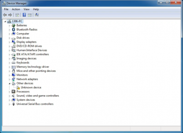
When you connect REV4 board to your computer at the first time, right click the icon of your “Computer” —>for “Properties”—> click the “Device manager”, under “Other Devices”, you should see an icon for “Unknown device” with a little yellow warning triangle next to it. This is your Arduino.<br> | |||
<br>[[Image:Driver 1.png|600px|frameless]]<br> | |||
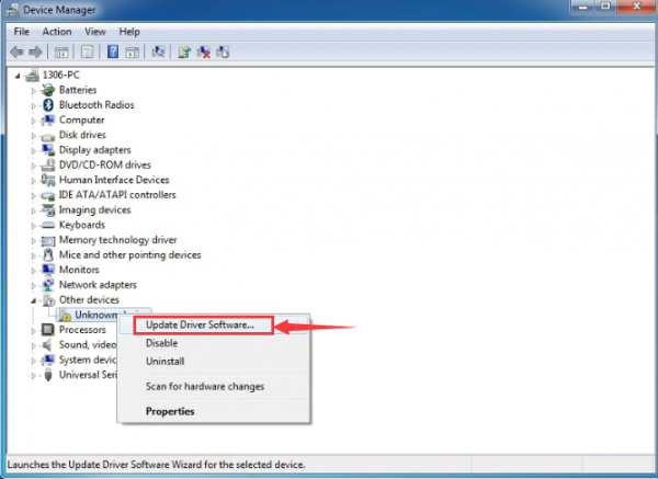
Then right-click on the device and select the top menu option (Update Driver Software...) shown as the figure below.. | |||
<br>[[Image:Driver 2.png|600px|frameless]]<br> | |||
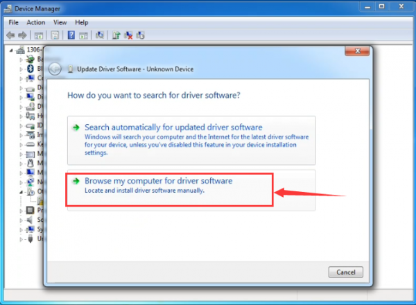
It will then be prompted to either “Search Automatically for updated driversoftware” or “Browse my computer for driver software”. Shown as below. In this page, select “Browse my computer for driver software”. | |||
<br>[[Image:Driver 3.png|600px|frameless]]<br> | |||
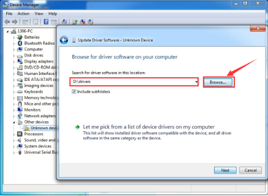
After that, select the option to browseand navigate to the “drivers” folder of Arduino installation. | |||
<br>[[Image:KS0286-4.png|800px|frameless]]<br> | |||
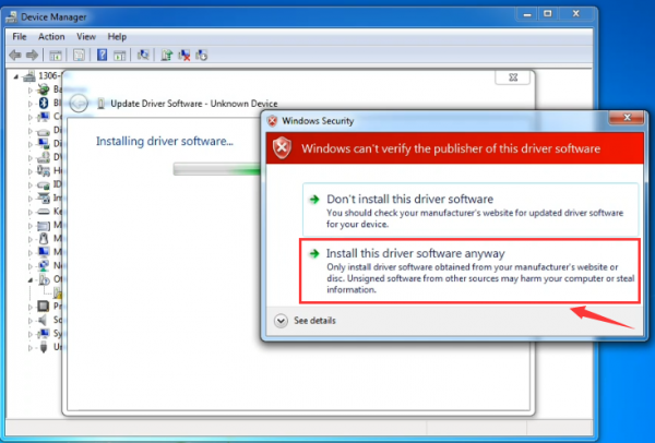
Click “Next” and you may get a security warning, if so, allow the software to be installed. Shown as below. | |||
<br>[[Image:Driver 5.png|600px|frameless]]<br> | |||
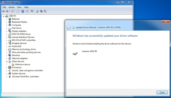
Once the software has been installed, you will get a confirmation message. Installation completed, click “Close”. | |||
<br>[[Image:Driver 6.png|600px|frameless]]<br> | |||
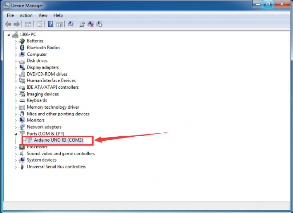
Up to now, the driver is installed well. Then you can right click “Computer” —>“Properties”—>“Device manager”, you should see the device as the figure shown below. | |||
<br>[[Image:Driver 7.png|600px|frameless]]<br> | |||
<br> | |||
'''Introduction for Arduino IDE Toolbar''' | |||
Double-click the icon of Arduino software downloaded well, you will get the interface shown below. | |||
<br>[[Image:Ks0313图片1.png|600px|frameless]]<br> | |||
('''Note:''' if the Arduino software loads in the wrong language, you can change it in the preferences dialog. See [https://www.arduino.cc/en/Guide/Environment-Languages the environment page] for details.) | |||
<br>[[Image:717.png|600px|frameless]]<br> | |||
<br> | |||
The functions of each button on the Toolbar are listed below: | |||
<br>[[Image:IDE.png|600px|frameless]]<br> | |||
{| class="wikitable" cellpadding="1" cellspacing="1" | |||
|- | |||
!scope="row" |[[Image:IDE 1.png|600px|frameless]] Verify/Compile | |||
| Check the code for errors | |||
|- | |||
!scope="row" |[[Image:IDE 2.png|600px|frameless]] Upload | |||
| Upload the current Sketch to the Arduino | |||
|- | |||
!scope="row" |[[Image:IDE 3.png|600px|frameless]] New | |||
| Create a new blank Sketch | |||
|- | |||
! scope="row" |[[Image:IDE 4.png|600px|frameless]] Open | |||
| Show a list of Sketches | |||
|- | |||
! scope="row" |[[Image:IDE 5.png|600px|frameless]] Save | |||
| Save the current Sketch | |||
|- | |||
! scope="row" |[[Image:IDE 6.png|600px|frameless]] Serial Monitor | |||
| Display the serial data being sent from the Arduino | |||
|- | |||
|} | |||
<br> | |||
=== Project 2: Joint Rotation and Pin Control === | |||
====Joint Rotation and Servo Angle Settings==== | |||
{| width="80%" cellspacing="0" border="1" | |||
|- | |||
! align="center" scope="col" | Name | |||
! align="center" scope="col" | 0° | |||
! align="center" scope="col" | 180° | |||
|- | |||
| align="center" | Servo 1(baseplate) | |||
| align="center" | Rotate toward the rightmost | |||
| align="center" | Rotate toward the leftmost | |||
|- | |||
| align="center" | Servo 2(right side) | |||
| align="center" | Rocker arm connected to Servo 2 stretches out | |||
| align="center" | draw back | |||
|- | |||
| align="center" | Servo 3(left side) | |||
| align="center" | Rocker arm connected to Servo 3 draws back | |||
| align="center" | stretches out | |||
|- | |||
| align="center" | Servo 4(clamp claw) | |||
| align="center" | closed | |||
| align="center" | opened | |||
|- | |||
|} | |||
<br> | |||
====Pin Control ==== | |||
{| width="50%" cellspacing="0" border="1" | |||
|- | |||
! align="center" scope="col" | Name | |||
! align="center" scope="col" | IO Pin | |||
|- | |||
| align="center" | Servo 1 (baseplate) | |||
| align="center" | A1 | |||
|- | |||
| align="center" | Servo 2 (left side) | |||
| align="center" | A0 | |||
|- | |||
| align="center" | Servo 3(right side) | |||
| align="center" | 8 | |||
|- | |||
| align="center" | Servo 4(clamp claw) | |||
| align="center" | 9 | |||
|- | |||
|- | |||
| align="center" | Right Joystick | |||
Revision as of 16:21, 11 June 2020
Introduction
On the Internet, we often see DIY robotic arm complete various actions. Do you want to have one? I believe that you’ll make your own robotic arm by learning our projects.
This kit includes R3 single-chip microcomputer, 2 rocker modules and 4 servos so on. We’ll teach you how to install and debug the robotic arm.
There are 3 ways of controlling metal manipulator in this kit:
1.Use a wired home-made joystick controller (included in the kit)
2.Control via Bluetooth. (HM -10 Bluetooth module included, support Bluetooth 4.0, Android and IOS system). we also provide relevant test code and specially designed APP for robotic arm.
3.Use wireless PS2 joystick (not included in kit) module to control. We only provide relevant test codes.
Features
- Detailed installation method.
- Detailed debugging methods, even you’re a beginner.
- 3 methods of controlling: wired joystick control, Bluetooth control, wireless PS2 joystick control.
- Relevant information provided
Specification
Keyestudio TB6612FNG Motor/Servo Drive Shield:
- VIN voltage: VIN = DC 7-15V
- VIN current: 5A
- Size: 73 * 53.34mm
- 2 way 5V outputs: 5V / 3A
- TB6612FNG: VIN input DC 7-15V, average drive current 1.2A, peak current 3.2A.
- PS2 interface: compatible with Sony PS2 receiver, can be plugged directly into the shield.
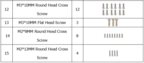
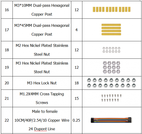
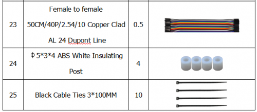
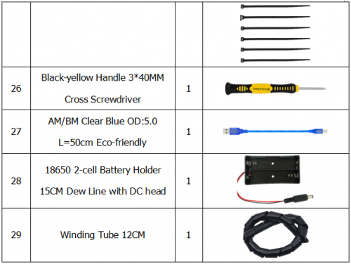
Component List
Robot Arm Projects
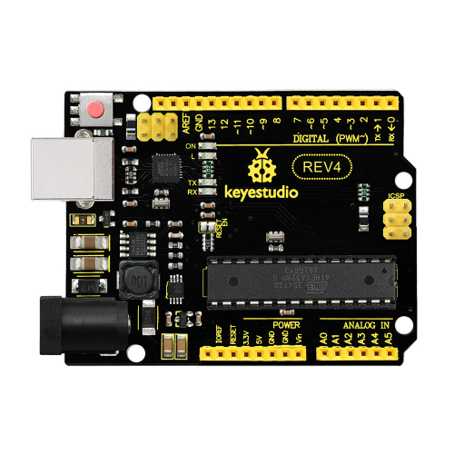
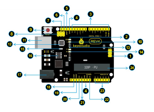
When it comes to using the UNO R3 as core of our robot, the UNO is the best board to get started with electronics and coding. If this is your first experience tinkering with the platform, the UNO is the most robust board you can start playing with. Well, let's at first have a look at this UNO R3 board.

|
ICSP (In-Circuit Serial Programming) Header In most case, ICSP is the AVR,an Arduino micro-program header consisting of MOSI, MISO, SCK, RESET, VCC, and GND. It is often called the SPI (serial peripheral interface) and can be considered an "extension" of the output. In fact, slave the output devices under the SPI bus host. |

|
Power LED Indicator
Powering the Arduino, LED on means that your circuit board is correctly powered on. If LED is off, connection is wrong. |

|
Digital I/O
Arduino REV4 has 14 digital input/output pins (of which 6 can be used as PWM outputs). These pins can be configured as digital input pin to read the logic value (0 or 1). Or used as digital output pin to drive different modules like LED, relay, etc. The pin labeled “〜” can be used to generate PWM. |

|
GND ( Ground pin headers)
Used for circuit ground |

|
AREF
Reference voltage (0-5V) for analog inputs. Used with analogReference(). |

|
SDA
IIC communication pin |

|
SCL
IIC communication pin |

|
ICSP (In-Circuit Serial Programming) Header
In most case, ICSP is the AVR,an Arduino micro-program header consisting of MOSI, MISO, SCK, RESET, VCC, and GND. Connected to ATMEGA 16U2-MU. When connecting to PC, program the firmware to ATMEGA 16U2-MU. |

|
RESET Button
You can reset your Arduino board, for example, start the program from the initial status. You can use the RESET button. |

|
D13 LED
There is a built-in LED driven by digital pin 13. When the pin is HIGH value, the LED is on, when the pin is LOW, it's off. |

|
USB Connection
Arduino board can be powered via USB connector. |

|
ATMEGA 16U2-MU
USB to serial chip, can convert the USB signal into serial port signal. |

|
TX LED
Onboard you can find the label: TX (transmit) |

|
RX LED
Onboard you can find the label: RX(receive ) |

|
Crystal Oscillator
How does Arduino calculate time? by using a crystal oscillator. |

|
Voltage Regulator
Convert an external input DC7-12V voltage into DC 5V, then switch DC 5V to the processor and other components. Output DC 5V, the drive current is 2A. |

|
DC Power Jack
Arduino board can be supplied with an external power DC7-12V from the DC power jack. |

|
IOREF
Used to configure the operating voltage of microcontrollers. Use it less. |

|
RESET Header
Connect an external button to reset the board. The function is the same as reset button (labeled 9) |

|
Power Pin 3V3
A 3.3 volt supply generated by the on-board regulator. Maximum current draw is 50 mA. |

|
Power Pin 5V
Provides 5V output voltage |

|
Vin
You can supply an external power input DC7-12V through this pin to Arduino board. |

|
Analog Pins
Arduino REV4 board has 6 analog inputs, labeled A0 through A5. |

|
Microcontroller
Each Arduino board has its own microcontroller. You can regard it as the brain of your board. |
Installing Arduino IDE
When you get the REV3 development board, first you should install the software and driver of Arduino. You can see all the Arduino software versions from the link below:
https://www.arduino.cc/en/Main/OldSoftwareReleases#1.5.x
Or you can browse the ARDUINO website at this link, https://www.arduino.cc, pop up the following interface.
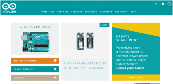
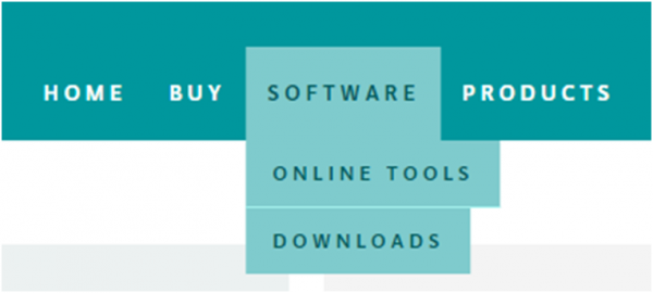
Then click the SOFTWARE on the browse bar, you will have two options ONLINE TOOLS and DOWNLOADS.
Click DOWNLOADS, it will appear the latest software version of ARDUINO 1.8.5 shown as below.
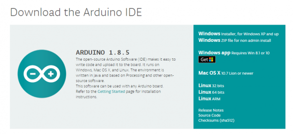
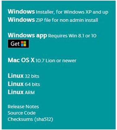
In this software page, on the right side you can see the version of development software for different operating systems. So ARDUINO has a rather powerful compatibility. You should download the software that is compatible with the operating system of your computer.
In our project, we will take WINDOWS system as an example here. There are also two options under Windows system, one is installed version, the other is non-installed version.
For simple installed version, first click Windows Installer, you will get the following page.

This way you just need to click JUST DOWNLOAD, then click the downloaded file to install it.
For non-installed version, first click Windows ZIP file, you will also get the pop-up interface as the above figure.
Click JUST DOWNLOAD, and when the ZIP file is downloaded well to your computer, you can directly unzip the file and then click the icon of ARDUINO program to start it.
When you get the REV4 development board, first you should install the Arduino software and driver.
We usually use the Windows software Arduino 1.5.6 version. You can download it from the link below:
https://www.arduino.cc/en/Main/OldSoftwareReleases#1.5.x
Or you can browse the ARDUINO website to download the latest version from this link, https://www.arduino.cc, pop up the following interface.

Then click the SOFTWARE on the browse bar, you will have two options ONLINE TOOLS and DOWNLOADS.

Click DOWNLOADS, it will appear the latest software version of ARDUINO 1.8.5 shown as below.

In this software page, on the right side you can see the version of development software for different operating systems. ARDUINO has a powerful compatibility. You should download the software that is compatible with the operating system of your computer.
We will take WINDOWS system as an example here. There are also two options under Windows system, one is installed version, the other is non-installed version.
For simple installed version, first click Windows Installer, you will get the following page.


This way you just need to click JUST DOWNLOAD, then click the downloaded file to install it.
For non-installed version, first click Windows ZIP file, you will also get the pop-up interface as the above figure.
Click JUST DOWNLOAD, and when the ZIP file is downloaded well to your computer, you can directly unzip the file and click the icon of ARDUINO software to start it.
Installing Arduino (Windows)
Install Arduino with the exe. Installation package downloaded well.
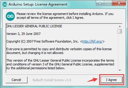
Click“I Agree”to see the following interface.
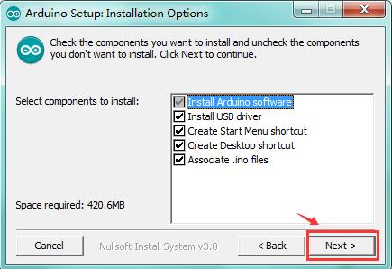
Click “Next”. Pop up the interface below.
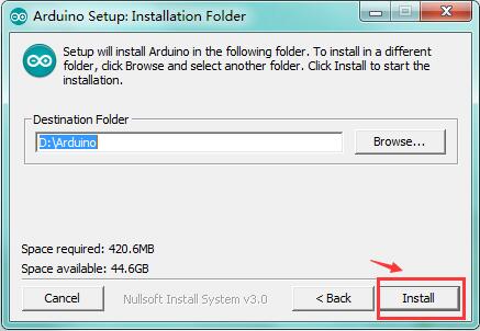
You can press Browse… to choose an installation path or directly type in the directory you want.
Then click “Install” to initiate installation.
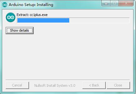
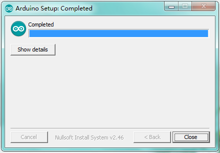
Wait for the installing process, if appear the interface of Window Security, just continue to click Install to finish the installation.
Installing Driver
Next, we will introduce the driver installation of REV4 development board. The driver installation may have slight differences in different computer systems. So in the following let’s move on to the driver installation in the WIN 7 system.
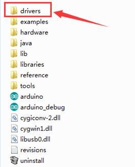
The Arduino folder contains both the Arduino program itself and the drivers that allow the Arduino to be connected to your computer by a USB cable. Before we launch the Arduino software, you are going to install the USB drivers.
Plug one end of your USB cable into the Arduino and the other into a USB socket on your computer.
When you connect REV4 board to your computer at the first time, right click the icon of your “Computer” —>for “Properties”—> click the “Device manager”, under “Other Devices”, you should see an icon for “Unknown device” with a little yellow warning triangle next to it. This is your Arduino.
Then right-click on the device and select the top menu option (Update Driver Software...) shown as the figure below..
It will then be prompted to either “Search Automatically for updated driversoftware” or “Browse my computer for driver software”. Shown as below. In this page, select “Browse my computer for driver software”.
After that, select the option to browseand navigate to the “drivers” folder of Arduino installation.
Click “Next” and you may get a security warning, if so, allow the software to be installed. Shown as below.
Once the software has been installed, you will get a confirmation message. Installation completed, click “Close”.
Up to now, the driver is installed well. Then you can right click “Computer” —>“Properties”—>“Device manager”, you should see the device as the figure shown below.
Introduction for Arduino IDE Toolbar
Double-click the icon of Arduino software downloaded well, you will get the interface shown below.
(Note: if the Arduino software loads in the wrong language, you can change it in the preferences dialog. See the environment page for details.)
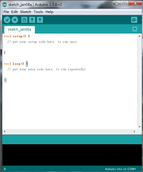
The functions of each button on the Toolbar are listed below:
![]()
Project 2: Joint Rotation and Pin Control
Joint Rotation and Servo Angle Settings
| Name | 0° | 180° |
|---|---|---|
| Servo 1(baseplate) | Rotate toward the rightmost | Rotate toward the leftmost |
| Servo 2(right side) | Rocker arm connected to Servo 2 stretches out | draw back |
| Servo 3(left side) | Rocker arm connected to Servo 3 draws back | stretches out |
| Servo 4(clamp claw) | closed | opened |
Pin Control
| Name | IO Pin |
|---|---|
| Servo 1 (baseplate) | A1 |
| Servo 2 (left side) | A0 |
| Servo 3(right side) | 8 |
| Servo 4(clamp claw) | 9 |
| Right Joystick |
