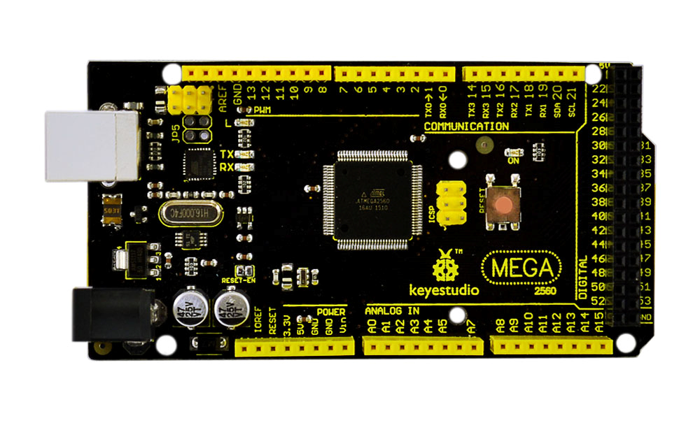
Ks0002 keyestudio Mega 2560 R3 Development Board
Introduction
Keyestudio Mega (core to ATmega2560) is a development board (used with16MHz crystal oscillator ) of microcontroller. There are 54 I/O (input/output ) digital interfaces (of which 14 are PWM outputs), 16 analog inputs and 4 UART (hardwareserial ports). With its bootloader, program can be downloaded directly with USB and you don’t need to use other external programmer. It can be driven directly by USB, or AC-to-DC adapter and battery.
Open source code and using C language development status in Java concept (cross platform) enable a rapid growth of Arduino peripheral module and application. The main reason attracting Artist to use Arduino is that they can quickly use all kinds of software communication such as Arduino language and Flash or Processing and so on to make multimedia interactive works. Development interface of Arduino IDE is based on the open source code, which you can
download freely. You can use them in thematic making, school teaching, television controlling, interactive projects and so on.].

Design of Power Supply
There are two choices (direct power supply trough USB or external power supply) for the power supply system of Arduino Mega, and they can be Automatic switched. External power supply can be AC-to-DC adapter or battery. Voltage input of this control board is 6V~12V, but if the supplied voltage is greater than 12V, the voltage stabilizing device will be likely to be overheated and damaging Arduino MEGA. So we suggest the power supply should be 6.5~12V in operation and recommended supply is 7.5 or 9V.
Cautions
The warnings and wrong operations possible cause dangerous.
Schematic
Specifications
| Microcontroller: | ATmega2560 |
|---|---|
| OperatingVoltage: | 5V |
| Input Voltage (recommended): | 7-12V |
| Input Voltage (limits): | 6-20V |
| Digital I/O Pins: | 54 (of which 15 provide PWM output) |
| Analog Input Pins: | 16 |
| DC Current per I/O Pin: | 20 mA |
| DC Current for 3.3V Pin: | 50 mA |
| Flash Memory: | 256 KB of which 8 KB used by bootloader |
| SRAM: | 8 KB |
| EEPROM: | 4 KB |
| Clock Speed: | 16 MHz |
Procedure for Installing Arduino Driver
To download the Arduino developing software on the web address: http:/arduino.cc/en/Main/Software. The downloaded file is arduino-1.0.zip, a compressed folder, to decompress it to the hard disk.
When 2560R3 Developing Board is connected to the Windows through the USB line, Windows will prompt a new USB device is found, then it will lead us into the "found new hardware wizard" window.
The next step is to install 2560R3 driver required, selecting the option of "install from a list or specific location (Senior)" and click "next" button:
To put the driver into the driver directory of Arduino 1.0 installation directory, and we need to specify this directory to be the searched directory when installing the driver.
Click "next" button, Windows begins to find and install Arduino driving procedure.
If all goes well, we will see the success interface as follows: After the installation of Arduino driver is successful, we can find the corresponding Arduino serial port in the Windows device manager: Well, the next is to test driver installation.
Programming
void setup() {
// initialize digital pin 13 as an output.
pinMode(13, OUTPUT);
}
// the loop function runs over and over again forever void loop() {
digitalWrite(13, HIGH);   // turn the LED on (HIGH is the voltage level)
delay(1000);              // wait for a second
digitalWrite(13, LOW);    // turn the LED off by making the voltage LOW
delay(1000);              // wait for a second
}
Copy the code above to Arduino IDE, select the board 2560 and com port, and then click upload. After uploading is done, you can see the Pin13 LED blinks with an interval of 1S. Then you know the driver is successfully installed.
Support
If you have questions or other better design ideas, you can go to our forum or wish to discuss.
Additional Idea
The Additional Idea is the place to write your project ideas about this product, or other usages you've found. Or you can write them on Projects page.
How to Buy
Licensing
This documentation is licensed under the Creative Commons Attribution-ShareAlike License 3.0 Source code and libraries are licensed under GPL/LGPL, see source code files for details.
External Links
Links to external webpages which provide more application ideas, documents/datasheet or software libraries