Ks0068 keyestudio 37 in 1 Sensor Kit for Arduino Starters: Difference between revisions
Keyestudio (talk | contribs) |
Keyestudio (talk | contribs) |
||
| Line 552: | Line 552: | ||
digitalWrite(ledPin, LOW); // Turn off LED when the sensor is not triggered | digitalWrite(ledPin, LOW); // Turn off LED when the sensor is not triggered | ||
} | } | ||
} | |||
******************************************************************************* | |||
</pre> | |||
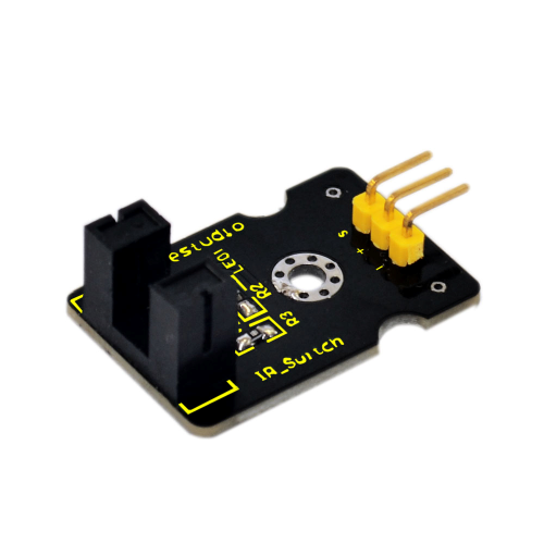
=== '''Project 13: Photo interrupter module '''=== | |||
<br>[[File:ks0068 13-1.png|500px|frameless|thumb]]<br> | |||
'''Introduction:'''<br> | |||
Upright part of this sensor is an infrared emitter and on the other side, it’s a shielded infrared detector. By emitting a beam of infrared light from one end to other end, the sensor can detect an object when it passes through the beam. It is used for many applications including optical limit switches, pellet dispensing, general object detection, etc. <br> | |||
'''Specification:'''<br> | |||
*Supply Voltage: 3.3V to 5V | |||
*Interface: Digital | |||
*Size: 30*20mm | |||
*Weight: 3g | |||
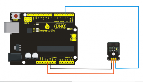
'''Connection Diagram:'''<br> | |||
<br>[[File:ks0068 13-2.png|500px|frameless|thumb]]<br> | |||
'''Sample Code:'''<br> | |||
<pre> | |||
***************************************************************************** | |||
// photo interrupter module | |||
int Led = 13 ;// define LED Interface | |||
int buttonpin = 3; // define the photo interrupter sensor interface | |||
int val ;// define numeric variables val | |||
void setup () | |||
{ | |||
pinMode (Led, OUTPUT) ;// define LED as output interface | |||
pinMode (buttonpin, INPUT) ;// define the photo interrupter sensor output interface | |||
} | |||
void loop () | |||
{ | |||
val = digitalRead (buttonpin) ;// digital interface will be assigned a value of 3 to read val | |||
if (val == HIGH) // When the light sensor detects a signal is interrupted, LED flashes | |||
{ | |||
digitalWrite (Led, HIGH); | |||
} | |||
else | |||
{ | |||
digitalWrite (Led, LOW); | |||
} | |||
} | |||
******************************************************************************* | |||
</pre> | |||
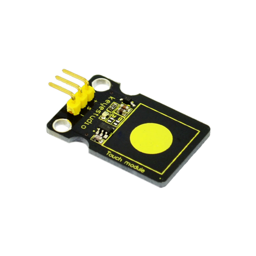
=== '''Project 14: Capacitive Touch Sensor '''=== | |||
<br>[[File:ks0068 14-1.png|500px|frameless|thumb]]<br> | |||
'''Introduction:'''<br> | |||
Are you tired of clicking mechanic button? Well, try our capacitive touch sensor. We can find touch sensors mostly on electronic device. So upgrade your Arduino project with our new version touch sensor and make it cool!! <br> | |||
This little sensor can "feel" people and metal touch and feedback a high/low voltage level. Even isolated by some cloth and paper, it can still feel the touch. Its sensetivity decrease as isolation layer gets thicker. For detail of usage, please check our wiki. To perfect user’s experience of our sensor module, we made following improvements. <br> | |||
'''Specification:'''<br> | |||
*Supply Voltage: 3.3V to 5V | |||
*Interface: Digital | |||
*Size: 30*20mm | |||
*Weight: 3g | |||
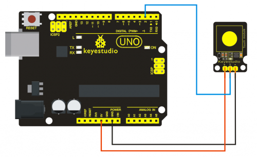
'''Connection Diagram:'''<br> | |||
<br>[[File:ks0068 14-2.png|500px|frameless|thumb]]<br> | |||
'''Sample Code:'''<br> | |||
<pre> | |||
***************************************************************************** | |||
int ledPin = 13; // Connect LED on pin 13, or use the onboard one | |||
int KEY = 2; // Connect Touch sensor on Digital Pin 2 | |||
void setup(){ | |||
pinMode(ledPin, OUTPUT); // Set ledPin to output mode | |||
pinMode(KEY, INPUT); //Set touch sensor pin to input mode | |||
} | |||
void loop(){ | |||
if(digitalRead(KEY)==HIGH) { //Read Touch sensor signal | |||
digitalWrite(ledPin, HIGH); // if Touch sensor is HIGH, then turn on | |||
} | |||
else{ | |||
digitalWrite(ledPin, LOW); // if Touch sensor is LOW, then turn off the led | |||
} | |||
} | |||
******************************************************************************* | |||
</pre> | |||
=== '''Project 15: Knock Sensor Module '''=== | |||
<br>[[File:ks0068 15-1.png|500px|frameless|thumb]]<br> | |||
'''Introduction:'''<br> | |||
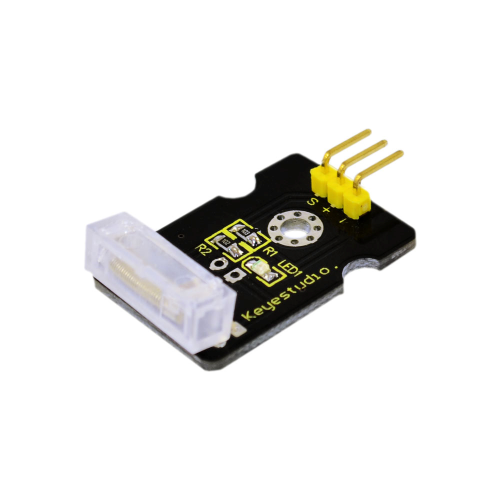
This module is a knock sensor. When you knock it, it can send a momentary signal. We can combine it with Arduino to make some interesting experiment, e.g. electronic drum. <br> | |||
'''Specification:'''<br> | |||
*Working voltage: 5V | |||
*Size: 30*20mm | |||
*Weight: 3g | |||
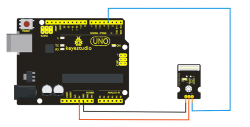
'''Connection Diagram:'''<br> | |||
<br>[[File:ks0068 15-2.png|500px|frameless|thumb]]<br> | |||
'''Sample Code:'''<br> | |||
<pre> | |||
***************************************************************************** | |||
Sample Code | |||
int Led=13;//define LED interface | |||
int Shock=3//define knock sensor interface | |||
;int val;//define digital variable val | |||
void setup() | |||
{ | |||
pinMode(Led,OUTPUT);//define LED to be output interface | |||
pinMode(Shock,INPUT);//define knock sensor to be output interface | |||
} | |||
void loop() | |||
{ | |||
val=digitalRead(Shock);//read the value of interface3 and evaluate it to val | |||
if(val==HIGH)//when the knock sensor detect a signal, LED will be flashing | |||
{ | |||
digitalWrite(Led,LOW); | |||
} | |||
else | |||
{ | |||
digitalWrite(Led,HIGH); | |||
} | |||
} | } | ||
******************************************************************************* | ******************************************************************************* | ||
</pre> | </pre> | ||
Revision as of 13:42, 26 August 2016
37 in 1 box for Arduino starters
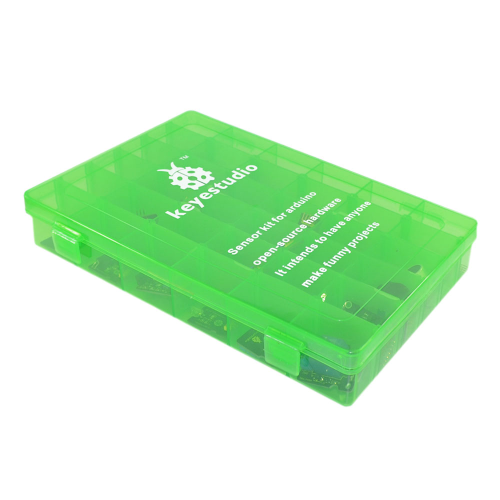
Sensor kit for Arduino
Based on open-source hardware
37 various sensors in one box
For you to make interesting projects
1. Summary
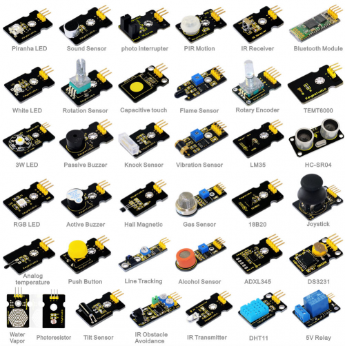
This is an Arduino sensor learning kit developed by Keyestudio. We bring together 36 basic sensors and modules, aiming for the convenience of its learning for starters. Inside this box, there are digital and analog sensors and also some special modules such as ultrasonic, bluetooth,, acceleration modules etc. For each module, there is clear connection diagram and sample code. So even if you are totally new at this, you can get started easily.
The sample codes for this sensor kit are based on ARDUINO because it's open source and easy. And if you are good at this, you can also apply this kit to other MCU development platform, such as 51, STM32, Raspberries Pi. The working principle is pretty much the same.
Now, let us embrace this fascinating world of ARDUINO and learn together!
2. Kit list
1: Digital White LED Light Module project
2: Piranha LED Light Module
3: 3W LED Module
4: RGB LED module
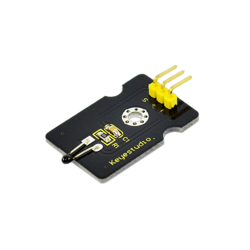
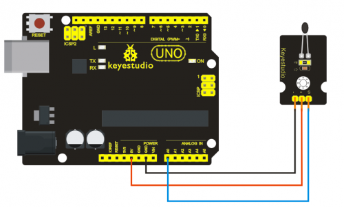
5: Analog temperature sensor
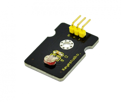
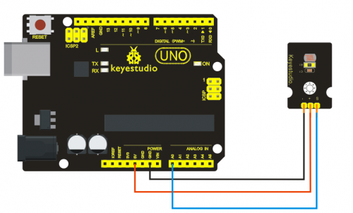
6: Photocell sensor
7: Analog Sound Sensor
8: Analog Rotation Sensor
9: Passive Buzzer module
10: Digital Buzzer Module
11: Digital Push Button
12: Digital Tilt Sensor
13: photo interrupter module
14. Capacitive Touch Sensor
15: Knock Sensor Module
16: Hall Magnetic Sensor
17: Line Tracking Sensor
18: Infrared Obstacle Avoidance Sensor
19: PIR Motion Sensor
20: Flame Sensor
21: Vibration Sensor
22: Analog Gas Sensor
23: Analog Alcohol Sensor
24: Digital IR Transmitter Module
25: Digital IR Receiver Module
26: Rotary Encoder module
27: LM35 Temperature Sensor
28: 18B20 Temperature Sensor
29: ADXL345 Three Axis Acceleration Module
30: DHT11 Temperature and Humidity Sensor
31: Bluetooth Module
32: TEMT6000 ambient light sensor
33: Keyestudio SR01 Ultrasonic Sensor
34: Joystick Module
35: DS3231 Clock Module
36: 5V Relay Module
37: Vapor Sensor
3. Project Details
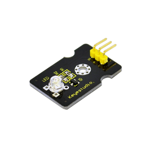
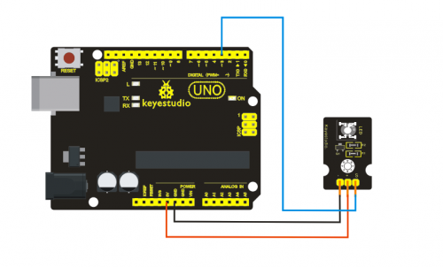
Project 1: LED Light Module
Introduction:
This LED light module has a shiny color, ideal for Arduino starters. It can be easily connected to IO/Sensor shield.
Specification:
- Type: Digital
- PH2.54 socket
- White LED light module
- Enables interaction with light-related works
- Size: 30*20mm
- Weight: 3g
Sample Code:
*****************************************************************************
int led = 3;
 void setup()
{
  pinMode(led, OUTPUT);     //Set Pin3 as output
}
void loop()
{
          digitalWrite(led, HIGH);   //Turn on led
          delay(2000);
          digitalWrite(led, LOW);    //Turn off led
          delay(2000);
}
*******************************************************************************
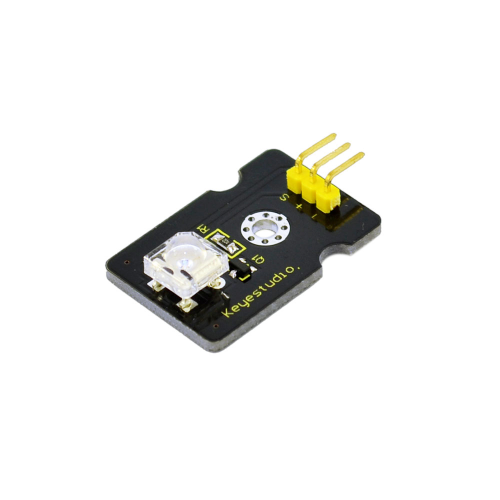
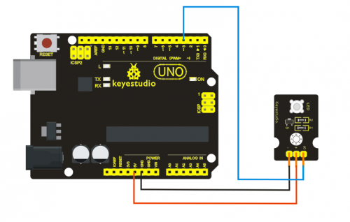
Project 2: Piranha LED Light Module
Introduction:
This is a special LED module. When you connect it to ARDUINO development board, after program, it can emit beautiful light. Of course, you can also control it using PWM. It will be like fireflies at night. Isn’t cool? We can also combine it with other sensors to do various interesting interactive experiments.
Specification:
- Module type: digital
- Working voltage: 5v
- Distance between pins: 2.54mm
- Size: 30*20mm
- Weight: 3g
Sample Code:
*****************************************************************************
int led = 3;
void setup()
{
  pinMode(led, OUTPUT);     //Set Pin3 as output
}
void loop()
{      digitalWrite(led, HIGH);   //Turn off led
          delay(2000);
          digitalWrite(led, LOW);    //Turn on led
          delay(2000);
}
*******************************************************************************
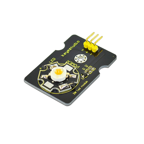
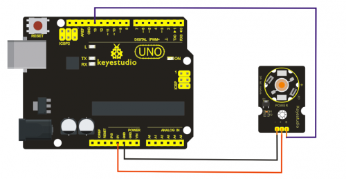
Project 3: 3W LED Module
Introduction:
This LED module is of high brightness because the lamp beads it carries is 3w. We can apply this module to Arduino projects. For example, intelligent robots can use this module for illumination purpose.
Please note that the LED light can't be exposed directly to human eyes for safety concerns.
Specification:
- Color temperature: 6000~7000K
- Luminous flux: 180~210lm
- Current: 700~750mA
- Power: 3W
- Light angle: 140 degree
- Working temperature: -50~80'C
- Storage temperature: -50~100'C
- High power LED module, controlled by IO port microcontroller
- Great for Robot and search & rescue platform application
- IO Type: Digital
- Supply Voltage: 3.3V to 5V
- Size: 40x28mm
- Weight: 6g
Sample Code:
*****************************************************************************
// the setup function runs once when you press reset or power the board
void setup() {
  // initialize digital pin 13 as an output.
  pinMode(13, OUTPUT);
}

// the loop function runs over and over again forever
void loop() {
  digitalWrite(13, HIGH);   // turn the LED on (HIGH is the voltage level)
  delay(1000);              // wait for a second
  digitalWrite(13, LOW);    // turn the LED off by making the voltage LOW
  delay(1000);              // wait for a second
}
*******************************************************************************
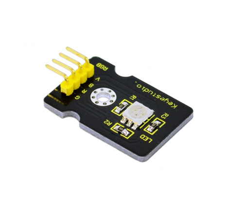
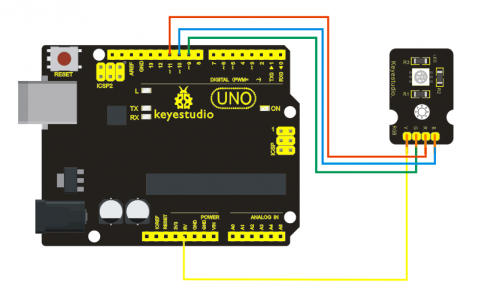
Project 4: RGB LED module
Introduction:
This is a full-color LED module, which contains 3 basic colors-red, green and blue. They can be seen as separate LED lights. After program, we can turn them on and off by sequence. We can also use PWM analog output to mix the three colors to generate different colors.
Specification:
- Color: red, green and blue
- Brightness: High
- Voltage: 5V
- Input: digital level
- Size: 30 * 20mm
- Weight: 3g
Sample Code:
*****************************************************************************
int redpin = 11; //select the pin for the red LED
int bluepin =10; // select the pin for the blue LED
int greenpin =9;// select the pin for the green LED
int val;
void setup() {
  pinMode(redpin, OUTPUT);
  pinMode(bluepin, OUTPUT);
  pinMode(greenpin, OUTPUT);
  }
void loop()
{for(val=255; val>0; val--)
  {analogWrite(11, val);
   analogWrite(10, 255-val);
   analogWrite(9, 128-val);
   delay(1);
  }
for(val=0; val<255; val++)
  {analogWrite(11, val);
   analogWrite(10, 255-val);
   analogWrite(9, 128-val);
   delay(1);
}
}
*******************************************************************************
Project 5: RGB LED moduleAnalog temperature sensor
Introduction:
This module is based on the working principle of a thermistor (resistance varies with temperature change in the environment). It can sense temperature change in its surrounding and send the data to the analog IO in the Arduino board. All we need to do is to convert the sensor output data to degrees Celsius temperature by simple programming and display it. It's both convenient and effective, and it’s widely applied in gardening, home alarm system and other devices.
Specification:
- Interface type: analog
- Working voltage: 5V
- Temperature range: -55℃~315℃
- Size: 30*20mm
- Weight: 3g
Sample Code:
*****************************************************************************
void setup()
{Serial.begin(9600);
}
// the loop routine runs over and over again forever:
void loop()
{int sensorValue = analogRead(A0);
Serial.println(sensorValue);
  delay(1); }
We can see that the analog value is changing according to the temperature change in the environment. But it’s not very obvious. Let’s solve this by using the following equation. The value read from the serial port is similar to normal temperature, eg. The temperature right now is 30C.
#include <math.h>
double Thermister(int RawADC) {
double Temp;
Temp = log(((10240000/RawADC) - 10000));
Temp = 1 / (0.001129148 + (0.000234125 + (0.0000000876741 * Temp * Temp ))* Temp );
Temp = Temp - 273.15; // Convert Kelvin to Celcius
return Temp;
}
void setup()
{Serial.begin(9600);
} void loop() { Serial.print(Thermister(analogRead(0))); // display Fahrenheit Serial.println("c"); delay(500); }
*******************************************************************************
Project 6: Photocell sensor
Introduction:
Photocell is commonly seen in our daily life and is mainly used in intelligent switch, also in common electronic design. To make it easier and more effective, we supply corresponding modules.
Photocell is a semiconductor. It has features of high sensitivity, quick response, spectral characteristic, and R-value consistence, maintaining high stability and reliability in environment extremes such as high temperature, high humidity. It’s widely used in automatic control switch fields like cameras, garden solar lights, lawn lamps, money detectors, quartz clocks, music cups, gift boxes, mini night lights, sound and light control switches, etc.
Specification:
- Interface type: analog
- Working voltage: 5V
- Size: 30*20mm
- Weight: 3g
Sample Code:
*****************************************************************************
int sensorPin =A0 ;
int value = 0;
void setup()
{
 Serial.begin(9600); }
void loop()
{
 value = analogRead(sensorPin);

Serial.println(value, DEC);

delay(50); }

*******************************************************************************
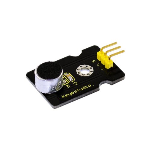
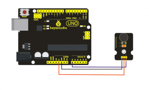
Project 7: Analog Sound Sensor
Introduction:
Analog Sound Sensor is typically used in detecting the loudness in ambient environment. The Arduino can collect its output signal by imitating the input interface. You can use it to make some interesting interactive works such as a voice operated switch.
Specification:
- Supply Voltage: 3.3V to 5V
- Detecting sound intensity
- Interface: Analog
- Size: 30*20mm
- Weight: 4g
Sample Code:
*****************************************************************************
void setup()
{
  Serial.begin(9600); // open serial port, set the baud rate to 9600 bps
}
void loop()
{
      int val;
      val=analogRead(0);   //connect mic sensor to Analog 0
      Serial.println(val,DEC);//print the sound value to serial
      delay(100);
}

*******************************************************************************
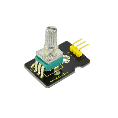
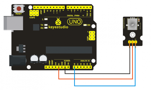
Project 8: Analog Rotation Sensor
Introduction:
This analog Rotation Sensor is arduino compatible. It is based on a potentiometer. Its voltage can be subdivided into 1024, easy to be connected to Arduino with our sensor shield. Combined with other sensors, we can make interesting projects by reading the analog value from the IO port.
Specification:
- Supply Voltage: 3.3V to 5V
- Interface: Analog
- Size: 30*20mm
- Weight: 8g
Sample Code:
*****************************************************************************
///Arduino Sample Code
void setup()
{
  Serial.begin(9600); //Set serial baud rate to 9600 bps
}
void loop()
{
int val;
val=analogRead(0);//Read rotation sensor value from analog 0
Serial.println(val,DEC);//Print the value to serial port
delay(100);
}
*******************************************************************************
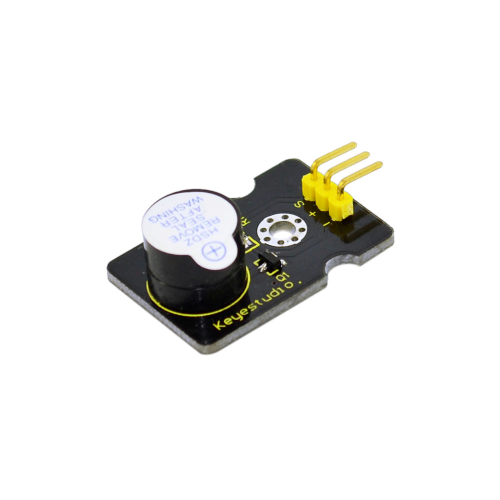
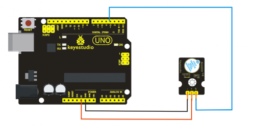
Project 9: Passive Buzzer module
Introduction:
We can use Arduino to make many interactive works of which the most commonly used is acoustic-optic display. All the previous experiment has something to do with LED. However, the circuit in this experiment can produce sound. Normally, the experiment is done with a buzzer or a speaker while buzzer is simpler and easier to use. The buzzer we introduced here is a passive buzzer. It cannot be actuated by itself, but by external pulse frequencies. Different frequencies produce different sounds. We can use Arduino to code the melody of a song, which is actually quite fun and simple.
Specification:
- Working voltage: 3.3-5v
- Interface type: digital
- Size: 30*20mm
- Weight: 4g
Sample Code:
*****************************************************************************
int buzzer=8;//set digital IO pin of the buzzer
void setup()
{
pinMode(buzzer,OUTPUT);// set digital IO pin pattern, OUTPUT to be output
}
void loop()
{ unsigned char i,j;//define variable
while(1)
{ for(i=0;i<80;i++)// output a frequency sound
{ digitalWrite(buzzer,HIGH);// sound
delay(1);//delay1ms
digitalWrite(buzzer,LOW);//not sound
delay(1);//ms delay
}
for(i=0;i<100;i++)// output a frequency sound
{
digitalWrite(buzzer,HIGH);// sound
digitalWrite(buzzer,LOW);//not sound

delay(2);//2ms delay
}
}
}
*******************************************************************************
After downloading the program, buzzer experiment will been finished.
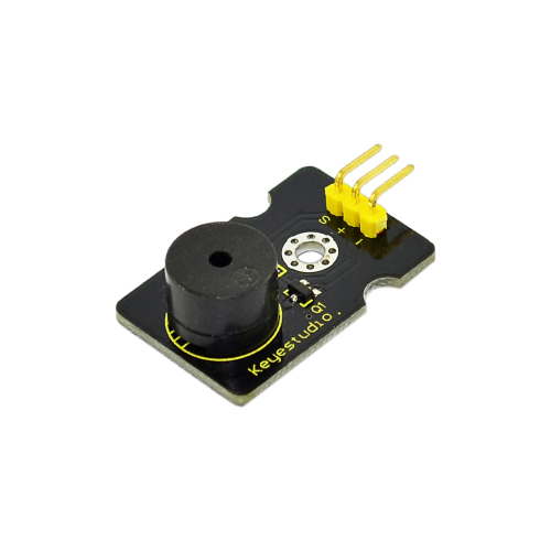
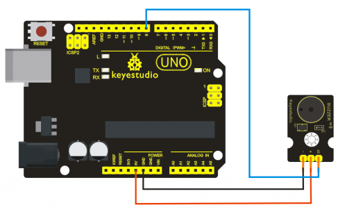
Project 10: Digital Buzzer Module
Introduction:
Here is the simplest sound making module. You can use high/low level to drive it. Changing the frequency it buzzes can produce different sound. This module is widely used on your daily appliance, like PC, refrigerator, phones etc. And you can also create many interesting interactive project with this small but useful module.
Just try it!! You will find the electronic sound it creates so fascinating.
Specification:
- Working voltage: 3.3-5v
- Interface type: digital
- Size: 30*20mm
- Weight: 4g
Sample Code:
*****************************************************************************
int buzzPin =  3;    //Connect Buzzer on Digital Pin3
 void setup()
 {
  pinMode(buzzPin, OUTPUT);
}
 void loop()
{
  digitalWrite(buzzPin, HIGH);
  delay(1);
  digitalWrite(buzzPin, LOW);
  delay(1);
}
*******************************************************************************
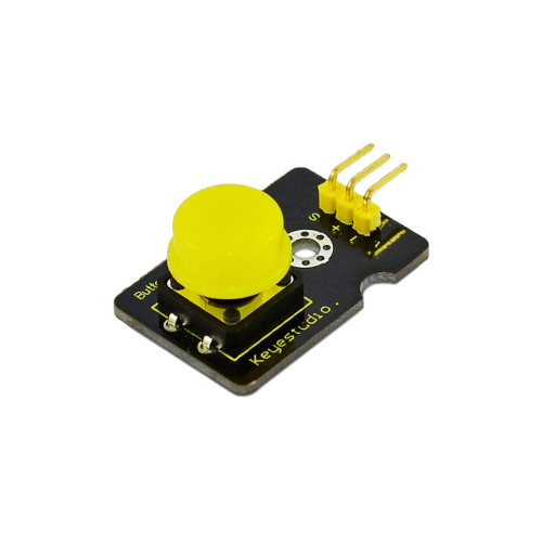
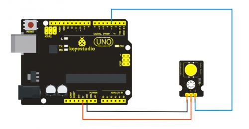
Project 11: Digital Push Button
Introduction:
This is a basic application module. You can simply plug it into an IO shield to have your first taste of Arduino.
Advantages:
Wide voltage range from 3.3V to 5V
Standard assembling structure (two 3mm diameter holes with multiple of 5mm as distance from center)
Easily recognizable interfaces of sensors ("A" for analog and "D" for digital)
Icons illustrate sensor function clearly
High quality connector
Immersion gold surface
Specification:
- Supply Voltage: 3.3V to 5V
- Easy to 'plug and operate'
- Large button keypad and high-quality first-class cap
- Achieve interesting and interactive work
- Interface: Digital
- Size: 30*20mm
- Weight: 4g
Sample Code:
*****************************************************************************
/* # When you push the digital button, the Led 13 on the board will turn on. Otherwise,the led turns off.
*/
int ledPin = 13;                // choose the pin for the LED
int inputPin = 3;               // Connect sensor to input pin 3
void setup() {
  pinMode(ledPin, OUTPUT);      // declare LED as output
  pinMode(inputPin, INPUT);     // declare pushbutton as input
}
void loop(){
  int val = digitalRead(inputPin);  // read input value
  if (val == HIGH) {            // check if the input is HIGH
    digitalWrite(ledPin, LOW);  // turn LED OFF
  } else {
    digitalWrite(ledPin, HIGH); // turn LED ON
  }
  }
*******************************************************************************
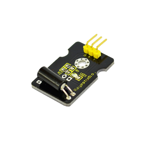
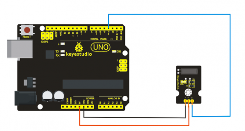
Project 12: Digital Tilt Sensor
Introduction:
Tilt Sensor is a digital tilt switch. It can be used as a simple tilt sensor. Simplly plug it to our IO/Sensor shield; you can make amazing interactive projects. With dedicated sensor shield and Arduino, you can achieve interesting and interactive work.
Specification:
- Supply Voltage: 3.3V to 5V
- Interface: Digital
- Size: 30*20mm
- Weight: 3g
Sample Code:
*****************************************************************************
int ledPin = 13;                // Connect LED to pin 13
int switcher = 3;                 // Connect Tilt sensor to Pin3

void setup()
{
  pinMode(ledPin, OUTPUT);      // Set digital pin 13 to output mode
  pinMode(switcher, INPUT);       // Set digital pin 3 to input mode
}
void loop()
{

   if(digitalRead(switcher)==HIGH) //Read sensor value
     {
        digitalWrite(ledPin, HIGH);   // Turn on LED when the sensor is tilted
     }
   else
     {
        digitalWrite(ledPin, LOW);    // Turn off LED when the sensor is not triggered
     }
}
*******************************************************************************
Project 13: Photo interrupter module
Introduction:
Upright part of this sensor is an infrared emitter and on the other side, it’s a shielded infrared detector. By emitting a beam of infrared light from one end to other end, the sensor can detect an object when it passes through the beam. It is used for many applications including optical limit switches, pellet dispensing, general object detection, etc.
Specification:
- Supply Voltage: 3.3V to 5V
- Interface: Digital
- Size: 30*20mm
- Weight: 3g
Sample Code:
*****************************************************************************
// photo interrupter module

int Led = 13 ;// define LED Interface
int buttonpin = 3; // define the photo interrupter sensor interface
int val ;// define numeric variables val
void setup ()
{
  pinMode (Led, OUTPUT) ;// define LED as output interface
  pinMode (buttonpin, INPUT) ;// define the photo interrupter sensor output interface
}
void loop ()
{
  val = digitalRead (buttonpin) ;// digital interface will be assigned a value of 3 to read val
  if (val == HIGH) // When the light sensor detects a signal is interrupted, LED flashes
  {
    digitalWrite (Led, HIGH);
  }
  else
  {
    digitalWrite (Led, LOW);
  }
}
*******************************************************************************
Project 14: Capacitive Touch Sensor
Introduction:
Are you tired of clicking mechanic button? Well, try our capacitive touch sensor. We can find touch sensors mostly on electronic device. So upgrade your Arduino project with our new version touch sensor and make it cool!!
This little sensor can "feel" people and metal touch and feedback a high/low voltage level. Even isolated by some cloth and paper, it can still feel the touch. Its sensetivity decrease as isolation layer gets thicker. For detail of usage, please check our wiki. To perfect user’s experience of our sensor module, we made following improvements.
Specification:
- Supply Voltage: 3.3V to 5V
- Interface: Digital
- Size: 30*20mm
- Weight: 3g
Sample Code:
*****************************************************************************
int ledPin = 13;                // Connect LED on pin 13, or use the onboard one
int KEY = 2;                 // Connect Touch sensor on Digital Pin 2

void setup(){
  pinMode(ledPin, OUTPUT);      // Set ledPin to output mode
  pinMode(KEY, INPUT);       //Set touch sensor pin to input mode
}

void loop(){
   if(digitalRead(KEY)==HIGH) {      //Read Touch sensor signal
        digitalWrite(ledPin, HIGH);   // if Touch sensor is HIGH, then turn on
     }
   else{
        digitalWrite(ledPin, LOW);    // if Touch sensor is LOW, then turn off the led
     }
}
*******************************************************************************
Project 15: Knock Sensor Module
Introduction:
This module is a knock sensor. When you knock it, it can send a momentary signal. We can combine it with Arduino to make some interesting experiment, e.g. electronic drum.
Specification:
- Working voltage: 5V
- Size: 30*20mm
- Weight: 3g
Sample Code:
*****************************************************************************
Sample Code
int Led=13;//define LED interface
int Shock=3//define knock sensor interface
;int val;//define digital variable val
void setup()
{
pinMode(Led,OUTPUT);//define LED to be output interface
pinMode(Shock,INPUT);//define knock sensor to be output interface
}
void loop()
{
val=digitalRead(Shock);//read the value of interface3 and evaluate it to val
if(val==HIGH)//when the knock sensor detect a signal, LED will be flashing
{
digitalWrite(Led,LOW);
}
else
{
digitalWrite(Led,HIGH);
}
}
*******************************************************************************
