Ks0069(72, 73) keyestudio Basic Starter Kit for Arduino Starters
keyestudio Basic Starter Kit for UNO and Mega
1. Kit Introduction
This is the basic Starter Kit, developed specially for those beginners who are interested in Arduino. You will have a set of Arduino's most common and useful electronic components. What's more. We will offer you a detailed tutorials including project introduction and their source codes.You may learn about Arduino through using these basic projects. This kit will help you control the physical world with sensors.
2.Kit Contents
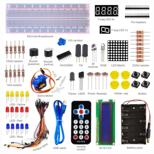
| Kit A for unoR3 | Kit B for 2560 R3 | Kit C Without board |
|---|---|---|
| UNO R3 | Mega 2560 | No controller board |
| 5x LED - Blue | 5x LED - Blue | 5x LED - Blue |
| 5x LED - Red | 5x LED - Red | 5x LED - Red |
| 5x LED - Yellow | 5x LED - Yellow | 5x LED - Yellow |
| 1x LED - RGB | 1x LED - RGB | 1x LED - RGB |
| 5x 10K Ω resistor | 5x 10K Ω resistor | 5x 10K Ω resistor |
| 5x 1K Ω resistor | 5x 1K Ω resistor | 5x 1K Ω resistor |
| 8x 220 Ω resistor | 8x 220 Ω resistor | 8x 220 Ω resistor |
| 1x 10K Ω Pot | 1x 10K Ω Pot | 1x 10K Ω Pot |
| 1x 7-seg LED 1x module | 1x 7-seg LED 1x module | 1x 7-seg LED 1x module |
| 1x 7-seg LED 4x module | 1x 7-seg LED 4x module | 1x 7-seg LED 4x module |
| 1x 8x8 LED Matrix | 1x 8x8 dot LED array | 1x 8x8 dot LED array |
| 1x Buzzer (active) | 1x Buzzer (active) | 1x Buzzer (active) |
| 1x Buzzer (passive) | 1x Buzzer (passive) | 1x Buzzer (passive) |
| 1x Flame sensor | 1x Flame sensor | 1x Flame sensor |
| 1x IR receiver | 1x IR receiver | 1x IR receiver |
| 1x IR remote control | 1x IR remote control | 1x IR remote control |
| 1x LM35 Temp Sensor | 1x LM35 Temp Sensor | 1x LM35 Temp Sensor |
| 2x Ball tilt sensor | 2x Ball tilt sensor | 2x Ball tilt sensor |
| 3x Photo Resistor | 3x Photo Resistor | 3x Photo Resistor |
| 4x Small button switch | 4x Small button switch | 4x Small button switch |
| 1x IC 74HC595N 16-pin DIP | 1x IC 74HC595N 16-pin DIP | 1x IC 74HC595N 16-pin DIP |
| 1x LCD1602 | 1x LCD1602 | 1x LCD1602 |
| 1x 9g servo | 1x 9g servo | 1x 9g servo |
| 830-pin Breadboard | 830-pin Breadboard | 830-pin Breadboard |
| Dupont connector wires | Dupont connector wires | Dupont connector wires |
| 1x 6-cell AA Battery pack | 1x 6-cell AA Battery pack | 1x 6-cell AA Battery pack |
| 1x USB cable | 1x USB cable | 1x USB cable |
3. Project List
1.Hello World
2.LED Blinking
3.PWM
4.Traffic Light
5.LED Chase Effect
6.Button-controlled LED
7.Active Buzzer
8.Passive Buzzer
9.RGB LED
10.Photo Resistor
11.Flame Sensor
12.LM35 Temperature Sensor
13.Tilt Switch
14.IR Remote Control
15.Analog Value Reading
16.74HC595
17.1-digit LED Segment Display
18.4-digit LED Segment Display
19.8*8 LED Matrix
20.1602 LCD
21.9g Servo Control
4. Project Details
Project 1: Hello World
Introduction:
As for starters, we will begin with something simple. In this project, you only need an Arduino and a USB cable to start the "Hello World!" experiment. This is a communication test of your Arduino and PC, also a primer project for you to have your first try of the Arduino world!
Hardware Required:
1. Arduino board x1
2. USB cable x1
Sample Code:
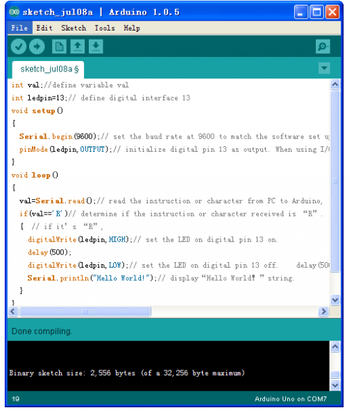
After installing driver for Arduino, let's open Arduino software and compile code that enables Arduino to print "Hello World!" under your instruction. Of course, you can compile code for Arduino to continuously echo "Hello World!" without instruction. A simple If () statement will do the instruction trick. With the onboard LED connected to pin 13, we can instruct the LED to blink first when Arduino gets an instruction and then print "Hello World!”.
int val;//define variable val
int ledpin=13;// define digital interface 13
void setup()
{
  Serial.begin(9600);// set the baud rate at 9600 to match the software set up. When connected to a specific device, (e.g. bluetooth), the baud rate needs to be the same with it.
  pinMode(ledpin,OUTPUT);// initialize digital pin 13 as output. When using I/O ports on an Arduino, this kind of set up is always needed.
}
void loop()
{
  val=Serial.read();// read the instruction or character from PC to Arduino, and assign them to Val.
  if(val=='R')// determine if the instruction or character received is “R”.
  {  // if it’s “R”,
    digitalWrite(ledpin,HIGH);// set the LED on digital pin 13 on.
    delay(500);
digitalWrite(ledpin,LOW);// set the LED on digital pin 13 off.    delay(500);

    Serial.println("Hello World!");// display“Hello World!”string.
}
Result:
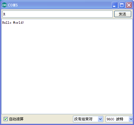
Screenshot
Click serial port monitor
Input R
LED 13 will blink once;
PC will receive information from Arduino: Hello World
After you choose the right port, the experiment should be easy for you!
Project 2: LED blinking
Introduction:
Blinking LED experiment is quite simple. In the "Hello World!" program, we have come across LED. This time, we are going to connect an LED to one of the digital pins rather than using LED13, which is soldered to the board. Except an Arduino and an USB cable, we will need extra parts as below:
Hardware Required:
1. Red M5 LED*1
2. 220Ω resistor*1
3. Breadboard*1
4. Breadboard jumper wires* several
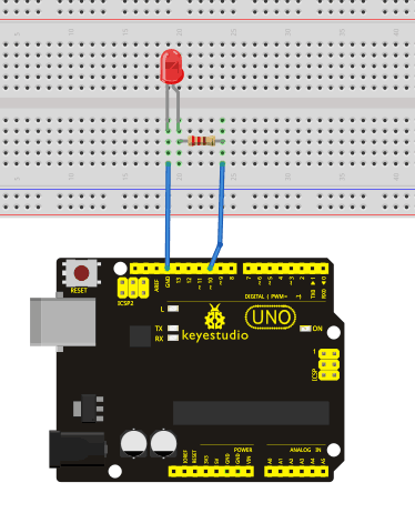
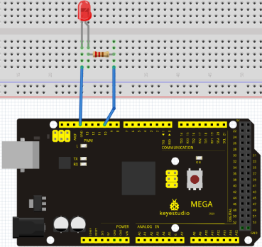
We follow below diagram from the experimental schematic link. Here we use digital pin 10. We connect LED to a 220 ohm resistor to avoid high current damaging the LED.
Sample Code:
int ledPin = 10; // define digital pin 10.
void setup()
{
pinMode(ledPin, OUTPUT);// define pin with LED connected as output.
}
void loop()
{
digitalWrite(ledPin, HIGH); // set the LED on.
delay(1000); // wait for a second.
digitalWrite(ledPin, LOW); // set the LED off.
delay(1000); // wait for a second
}
Result:
After downloading this program, in the experiment, you will see the LED connected to pin 10 turning on and off, with an interval approximately one second.
The blinking LED experiment is now completed. Thank you!
