Ks0198 keyestudio 4DOF Robot Mechanical Arm Kit for Arduino DIY
Kit Overview
How to DIY a robotic arm to complete multiple movements? Cool.With this keyestudio robotic arm kit, you are able to DIY your own controllable mechanical arm using ARDUINO microcontroller. It uses UNO R3 and 2 JoyStick modules to control the angle degree of 4 servos. When DIY this 4DOF robot arm kit, you could get everything needed for arm installation and debugging. There are 3 controlling methods are as follows: 1) Controlling through Wired JoyStick (included in the kit); 2) Phone Bluetooth Controlling (note: HC-06 Bluetooth module Not Included, only provide the test code for Bluetooth and APP for Android phone); 3) Wireless PS2 JoyStick Control (PS2 JoyStick module Not Included, we only provide the test code.) You are able to get all related information in the Arm kit. Take your brain on an inspiring journey through the world of programming. Get started now!
Kit Features
You can check out these features:
- Detailed installation instructions
- Detailed debugging methods, starting Arduino from entry.
- Three controlling methods: Wired JoyStick Control; Phone Bluetooth Control; Wireless PS2 JoyStick Control.
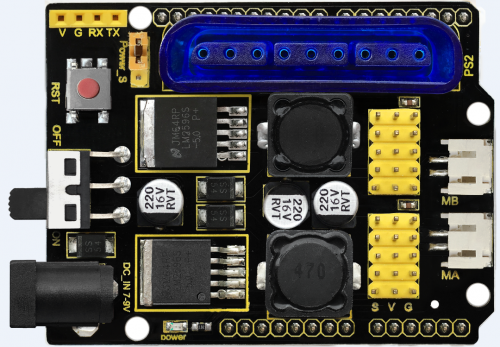
The parameters of keyestudio TB6612FNG motor/servo drive expansion board are as follows:
- VIN voltage: VIN = DC 7-15V
- VIN current: 5A
- Two-way 5V output: 5V/3A
- TB6612FNG: VIN input DC 7-15V; average drive current 1.2A; peak current 3.2A
- PS2 interface: compatible with Sony PS2 receiver, can be plugged directly into the expansion board.
- Dimensions: 73*53.34mm
Part List
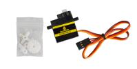
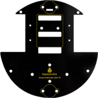
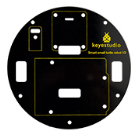
You can see a pretty beautiful packaging box for the arm kit, and inside the packaging you will find all the parts and screws listed below.
Assembly Guide
Follow the assembly steps below to build your own robot arm, believe you will be full of delight to experience the robot arm DIY. If still confused, you can refer to the assembly video.
Step1: Begin with the Baseplate Assembly
(1) Firstly, you should prepare the components as follows:
- M3*30+5MM single-pass copper pillar *4
- M3*6mm+6mm single-pass copper pillar *4
- M3 Hex Nut *8
- Black Acrylic plate *1
Then, screw the copper pillars with M3 hex nuts on the black Acrylic baseplate.
thumb
(2) Then install the control board, and prepare the components as follows:
- M3*6MM round-head screw *3
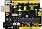
- Keyestudio UNO R3 board *1
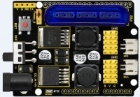
- keyestudio TB6612FNG motor shield *1
Firstly, screw the UNO R3 board on the pillar using three M3*6MM round-head screws.
thumb
Then stack the motor drive shield onto the UNO R3 board.
thumb
(3) Completed the above assembly, let's mount the Pivot Servo Plate onto the base.
- M3*12MM round-head screw *2
- M3 hex lock Nut *2
- Black 180° servo *1
- Acrylic plate * 4
Note: before install the servo, should set the servo angle to 80 degrees.
To set the servo angle, first connect the servo to A0 of motor shield, upload the code below to UNO R3 board, powered on, press the reset button, servo will rotate to 80°.
thumb
Code for 80° Servo:
int servopin=A0;//Define digital interface A0 to connect servo steering gear signal line
int myangle;     //Define angle variables
int pulsewidth; //Define pulse width variables
void setup()
{
pinMode(servopin,OUTPUT); //Set steering gear interface as Output
}
void servopulse(int servopin,int myangle) //Define Function
{
pulsewidth=(myangle*11)+500; //Converts the Angle to a pulse width value of 500 - 2480
digitalWrite(servopin,HIGH); //The steering gear interface level is high
delayMicroseconds(pulsewidth); //The microsecond number of the delay pulse width value
digitalWrite(servopin,LOW); //Turn the steering gear interface level to low
delay(20-pulsewidth/1000);
}
void loop()
{
servopulse(servopin,80); //Set steering gear Angle
}

//0 Degree Code:
//		servopulse(servopin,0);
//80 Degree Code:
//		servopulse(servopin,80);
//180 Degree Code:
//		servopulse(servopin,180);
Note:
Set well the servo angle and complete the below servo base plate assembly, power off the servo to avoid the angle error and make sure the servo can rotate freely. Don’t over-tighen the screws.
thumb
Adjusted well the servo motor, start to install the Servo Base Plate. Follow the marks.
thumb
Firstly mount the acrylic plate ② to the servo motor.
thumb
Then mount the two acrylic plates ④ to the servo using two M3*12MM round-head screws.
thumb
After that, screw the acrylic plate ⑤ to the servo using two M3 hex lock Nuts⑥.
thumb
You should get the detailed view shown below (pay close attention to red mark).
thumb
You should get the complete Servo Base Part.
thumb
(4) Now you should install the Servo Base part to the Base Plate:
- M3*6MM round-head hex screw *4
Install the Servo plate to the Base Plate using four M3*6MM round-head hex screws.
thumb
Step2: Assemble Arm Middle Parts
(1) In the following section, assemble the Left Arm Servo Plate. Prepare:
- M3*12MM round-head screw *2
- M3 hex lock nut *2
- M2x5MM Phillips tapping screw *1
- M2x8MM Phillips tapping screw *1
- Black 180° servo *1
- White servo mount *1
- Acrylic plate *5
Note: before install the servo plate, should set the servo angle to 180 degrees. The method is the same as 80° servo settings mentioned above. You just need to change the servopulse(servopin,80) into servopulse(servopin,180) in the code.
thumb
Now assemble the Left Arm Servo Plate as below.
(pay close attention to servo direction, rocker connected to servo and marked position)
thumb
Firstly mount the acrylic plate ② to the Left servo motor.
thumb
Second, mount the two acrylic plates ④ to the servo using two M3*12MM round-head screws③. You can get the Left servo plate shown below.
thumb
Then screw the Left servo plate to acrylic plate ⑤ using two M3 hex lock Nuts⑥. Get the Left servo base plate shown below.
thumb
After that, screw the acrylic plate joint and white servo mount ⑦ to the Left servo base plate using a M2x8MM tapping screw and a M2x5MM tapping screw⑧.
thumb
Finally you should get the complete Left Arm Servo Plate. Shown below.
thumb
(2) We will now attach a servo mount to the Arm Bottom Plate.
- M2x8MM Phillips tapping screw *2
- White servo mount *1
- Acrylic bottom plate *1
- Black Cylindrical holder *1
Fix the white servo mount and black Cylindrical holder on the acrylic plate using two M2x8MM Phillips tapping screws.
thumb
(3) Completed the above assembly, move on to the Right Arm Servo Plate.
- M3*12MM round-head screw *2
- M3 hex lock nut *2
- M2x5MM Phillips tapping screw *1
- M2x8MM Phillips tapping screw *1
- Black 180° servo *1
- White servo mount *1
- Black Acrylic plate *5
Note: before install the servo, should set the servo angle to 0 degrees.
The method is the same as 80° servo settings mentioned above.
You just need to change the servopulse(servopin,80) into servopulse(servopin,0) in the code.
thumb
Now assemble the Right Arm Servo Plate as below.
(pay close attention to servo direction, rocker connected to servo and marked position)
thumb
Firstly mount the acrylic plate ② to the Right servo motor.
Second, mount the two acrylic plates ④ to the servo using two M3*12MM round-head screws③.
Then screw the Right servo plate to acrylic plate ⑤ using two M3 hex lock Nuts⑥.
