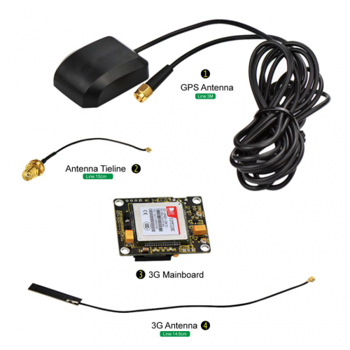
Ks0287 keyestudio SIM5320E 3G Module (Black)
keyestudio SIM5320E 3G Module (Black)
== Description ==
keyestudio SIM5320E 3G module is a mobile phone module, it can be used for GPRS data transmission, supporting both Mobile and Unicom. This module has the function of GPS positioning, with the features of powerful functions and less external circuits,etc. When registering the network and RF multi-slot sending,the current consumption peak may reach 2A, which will inevitably lead to voltage sags, so the power system generally requires more than 2A current supply capability.
==Interface Explanation ==
- Power Supply: DC 5V 2A or above.
- Communication Interface: a group of TTL-level serial port, compatible with 5V/3.3V microcontroller; with a USB interface, can be directly connected to the computer debugging.
- GPS Antenna Interface: a group of IPXmini antenna interface, the default connecting to active GPS antenna.
- GMS Antenna Interface: a group of IPXmini antenna interface, the default providing PCB antenna.
- SIM Card Interface: drawer type
- USB Interface: mini USB interface
- Voice Mike Interface: Lead out, the interface is a 2.54 * 4P single row pin form.
- Other Interfaces: a group of IIC interfaces, a group of interface can control the module’s opening and closing (the module default self-starting).
- Indicator LEDs: one LED is used to indicate the working status of the module; another 0603 LED is used to indicate the network status.
Preparation
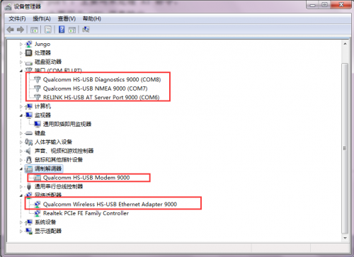
1、Insert the SIM card 2、J2: power supply DC 5V 2A 3、3G ANT interface: connecting 3G antenna 4、GPS ANT interface: connecting GPS antenna 5、Connecting to MICRO USB interface. Done drive installation, it will build communication between USB and system,5 ports will be mapped on the system as follows: USB Modem COM port:used to dial-up networking. AT command COM port:used to process AT command. NMEA COM port:used for GPS information output. Diagnostics COM port:used for debugging, grab the log information of module. Ethernet Adapter:not supporting.
1)Windows 7: 5 COM ports mapping shown in the below figure:
2)Linux: corresponding COM ports, such as:
      Device file simcom’s composite device;
      ttyUSB0 diag interface;
      ttyUSB1 nmea interface;
      ttyUSB2 at interface;
      ttyUSB3 modem interface;
      ttyUSB4 Wireless Ethernet Adapter interface.
3)Wince: corresponding COM ports, such as(only map out 3 com ports,ranging 1-9):
      "Index"=dword:X
      "FriendlyName"="SimTech HS-USB NMEA 9000"
      "Index"=dword:X
      "FriendlyName"="SimTech HS-USB ATCOM 9000"
      "Index"=dword:X
      "FriendlyName"="SimTech HS-USB Modem 9000"
COM Port Connection
1>. Send the AT command through the serial port on the J6 pin. Connect the RX pin of TTL level to STXD of module; TX is connected to SRXD; GND is connected to GND. Open the serial debugging software. Select the current port, set the baud rate to 115200. Specific as shown below:
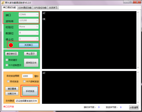
Set up well as the above figure, then open the serial port, in the string text field input AT, click Send, it will show AT OK. It means that the communication between the computer and the module is normal.
2>. Communicate with the computer via the serial port on the USB interface. The settings are the same as the above figure except the COM port. The specific AT command port as follows: ![]()
GPS Testing
Before using the GPS function, you should first check whether the GPS function is enabled by using the AT command, or directly open the GPS function. Use AT + CGPS =1, getting feedback OK, as shown below, you can view the corresponding information through GPS software.
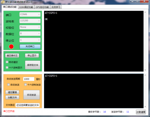
Select COM port like ![]() , set baud rate to 115200.
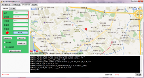
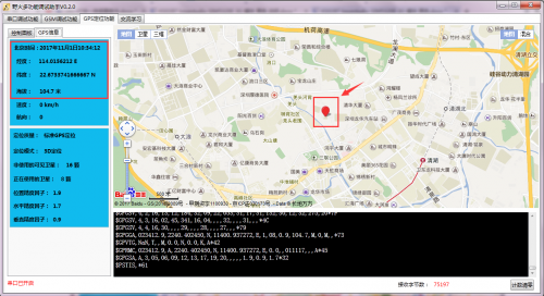
Setting well, open the serial port, you can see the related information about current positioning, including latitude, longitude, elevation and other information, as shown below.
, set baud rate to 115200.
Setting well, open the serial port, you can see the related information about current positioning, including latitude, longitude, elevation and other information, as shown below.
Calling Function
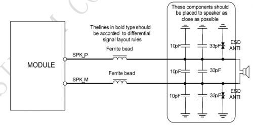
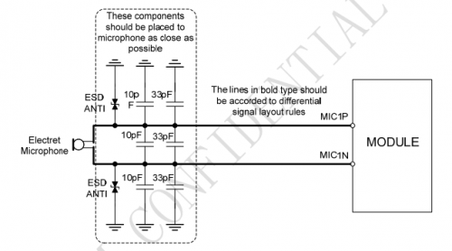
1、First,on the J9 of module, connect speakers to SPKM and SPKP, connect MIC to MICN and MICP.
Please refer to the corresponding circuit file like
