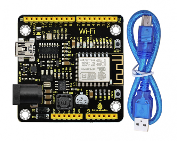
Ks0354 Keyestudio ESP8266 WI-FI Development Board
Description
This keyestudio ESP8266 WI-FI development board is based on the ESP8266-12FWIFI module developed by Ai-Thinker. The processor ESP8266 integrates the industry-leading Tensilica L106 ultra-low-power 32-bit micro MCU in a smaller package, with 16-bit Lite mode. The main frequency supports 80MHz and 160 MHz. It supports RTOS, integrated with Wi-Fi MAC/BB/RF/PA/LNA. Onboard comes with curved antenna. This development board is a standalone network controller, which can add networking function to those existing devices. It has 11 I/O ports (4 of which can be used as PWM output), and all I/O ports operate at 3.3V. It also comes with an AD input interface, supporting the voltage range of 0-3.3V. The board can be powered via the USB port, or with an external power supply (DC 7-12V), or powered by the female headers Vin/GND (DC 7-12V).
Technical Details
- Microcontroller: ESP8266-12F
- Operating Voltage: 3V3
- Input Voltage (recommended): DC 7-12V
- Digital I/O Pins: 8
(GPIO2, GPIO4, GPIO5, GPIO12, GPIO13, GPIO14, GPIO15, GPIO16)
- Analog Input Pins: 1 (A0)
- IO output maximum current: 12 mA
- Main frequency supports 80 MHz and 160 MHz
- LED_BUILTIN: GPIO 14
- Comes with an external power jack (DC 7-12V)
- Dimensions: 54mm*56mm*15mm
Element and Interfaces
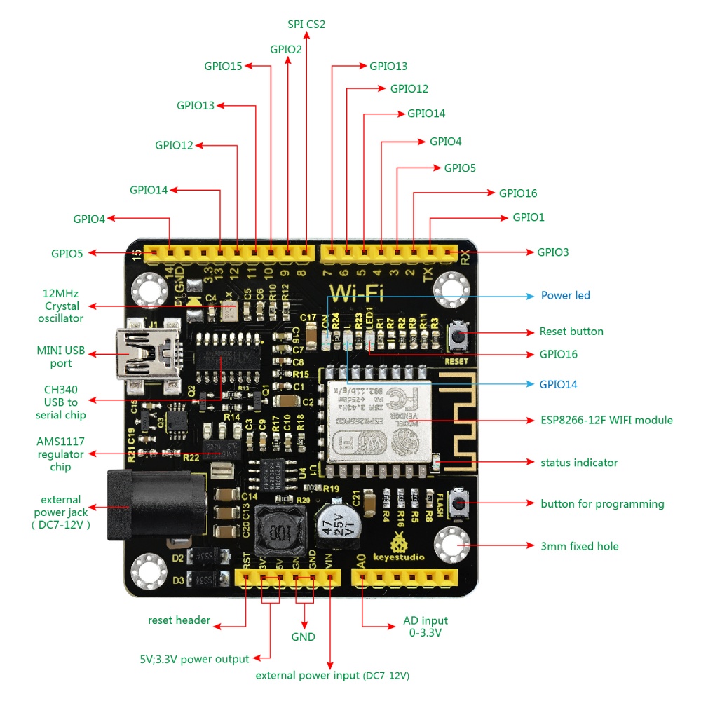
Here is an explanation of what every element and interface of the board does:

Specialized Functions of Some Pins
- Serial communication: GPIO3 (RX) and GPIO1 (TX).
- PWM Interfaces (Pulse-Width Modulation): GPIO 4, GPIO 12, GPIO 14, GPIO 15.
- SPI communication: GPIO6(CLK), GPIO7(MISO), GPIO8(MOSI), GPIO9 (HD), GPIO10(WP), GPIO1(CS1), GPIO0(CS2)
- IIC communication: GPIO2(SDA); GPIO14(SCL)
- IR Remote Control Interface: GPIO5(IR RX); GPIO14(IR TX)
Detailed Using Method as follows
Step1| Install the Arduino IDE
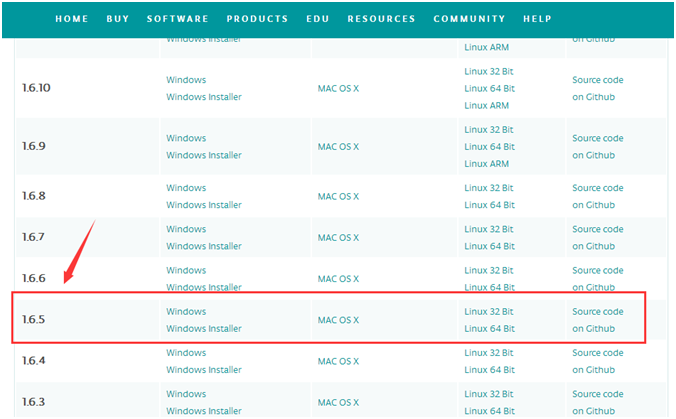
When programming the control board, first you should install the Arduinosoftware and driver. You can download the different versions for different systems from the link below: https://www.arduino.cc/en/Main/OldSoftwareReleases#1.5.x
NOTE: this control board is only compatible with Arduino 1.6.5 version or latest.
In the following, we will download the Arduino 1.6.5 version.

In this Windows system page, there are two options. One is Windows version, the other is Windows Installer.
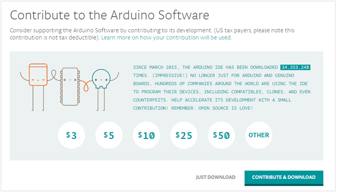
For Windows Installer, you can download the installation file, this way you need to install the arduino IDE.

For simple Windows version, you can download the software directly, do not need to install, just directly use the software after unzip the file.


