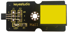
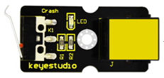
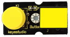
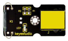
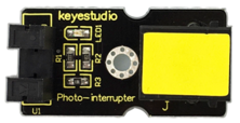
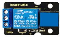
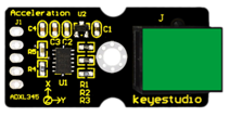
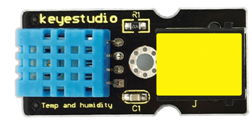
Ks0397 keyestudio EASY plug Super Starter Kit for Arduino STEM EDU
Kit Description
The keyestudio EASY PLUG super starter kit is based on Mixly blocks coding, very easy to use and flexible. This kit includes everything you need to complete Mixly projects that will teach you how to control and read external sensors and displays, control matrix, learn Mixly Blocks programming, and much more. Although you have a few or even no electronics related knowledge, you can use this kit to realize your creative ideas as long as you want to. After using this kit you’ll have the know-how to start creating your own amazing experiments. Share your own creative works with your intimate family, friends or classmates. Let’s get started right now!
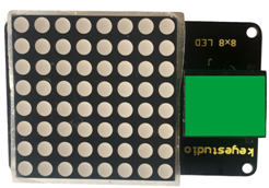
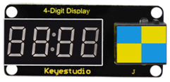
Kit List
Getting Started with Mixly
Introduction for Mixly
Mixly is a free open-source graphical Arduino programming software, based on Google’s Blockly graphical programming framework, and developed by Mixly Team@ BNU. It is a free open-source graphical programming tool for creative electronic development; a complete support ecosystem for creative e-education; a stage for maker educators to realize their dreams. Although there is an Ardublock graphical programming software launched by Arduino official, Ardublock is not perfect enough, and many common functions cannot be realized.
Interface Functions of Mixly
System Functions
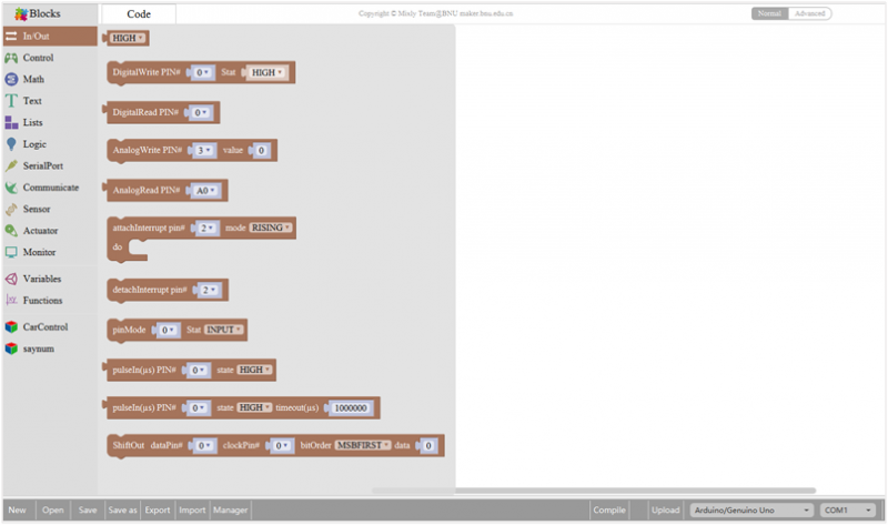
Look at the main interface of Mixly, it includes five parts, that is, Blocks selection, code edit, text code (hidden), system function and message prompt area. Shown below.
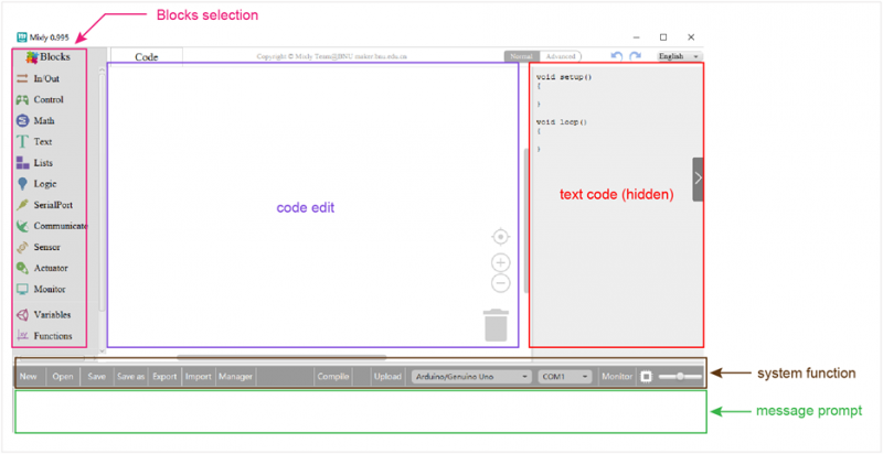
Some common functions:
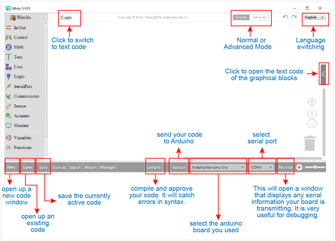
Through this interface, you can complete the code compile、upload、save and manage. It support four remove methods: drag it left out code window, or drag to Recycle Bin, delete key, or right-click to delete block. It supports four languages: English、Español (Spanish)、中文简体(Chinese Simplified)、中文繁体(Chinese Traditional).
In/Out Block
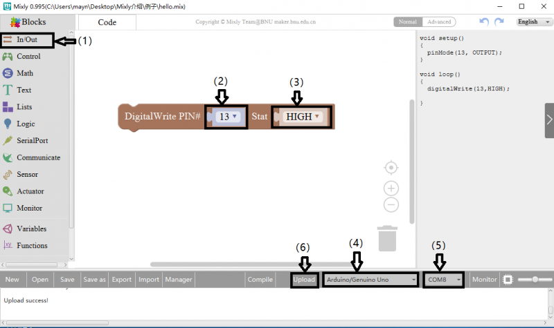
For example:
Connect your Arduino Uno board, then follow the steps below to light the Pin13 led on Arduino UNO.
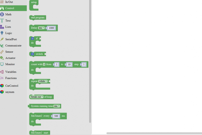
Control Block
| No. | BLOCK ICON | DEFINITION |
|---|---|---|
| 1 | 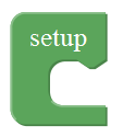 |
Initialization (run only once) |
| 2 |  |
End the program, means the program will stop running when use this block. |
| 3 |  |
Delay function, click to select ms or us (pause the program for the amount of time (in milliseconds) specified as parameter. There are 1000 milliseconds in a second.) |
| 4 | 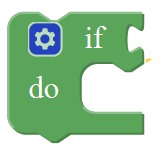 |
if_do function (first evaluate a value be true or false, if a value is true, then do some statement. You can click the blue gear icon to select the else if block or else block.) |
| 5 |  |
switch function. You can click the blue gear icon to select the case block or default block. (used to evaluate several programs then execute the corresponding function matched with program.) |
| 6 |  |
Equal to for statement. |
| 7 | 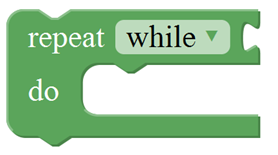 |
A while loop statement. |
| 8 |  |
break function, used to exit from the containing loop. |
| 9 |  |
millis() function, returns the system running time since the program started.
(The unit can be ms (milliseconds) or μs(microsecond)). |
| 10 | 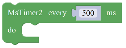 |
Timer interrupt function, that is, set a trigger interrupt for the amount of time (in milliseconds) specified as parameter. |
| 11 |  |
Timer interrupt start block |
| 12 |  |
Timer interrupt stop block |
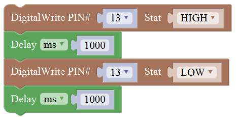
For example:
Compile and upload the program below to your Arduino board, you should see Pin13 LED on Arduino UNO continue to flash.(with an interval of 1s, equal to 1000ms)
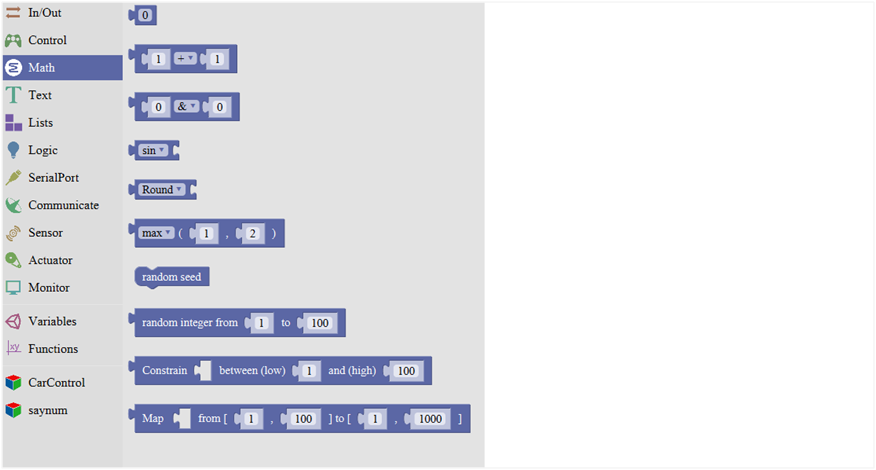
Math Block
| No. | BLOCK ICON | DEFINITION |
|---|---|---|
| 1 |  |
A number |
| 2 |  |
Click to select the Arithmetic Operators: +(addition);
-(subtraction);
x (Multiplication); ÷(division); %(remainder);
^(bitwise xor) |
| 3 |  |
Click to select the & (bitwise end); l (bitwise or); << (bitshift left); >> (bitshift right) |
| 4 |  |
Click to select the sin; cos; tan; asin; acos; atan; ln; log10; e^; 10^; ++ (increment) ; |
| 5 |  |
Click to select the Round; Ceil; Floor; abs; sq; sqrt Round: Returns the integer part a number using around. |
| 6 |  |
If select the max, returns the larger number; if select the min, returns the smaller number. |
| 7 |  |
Initialize the random seed |
| 8 |  |
Return a random integer between the two specified limits, inclusive. |
| 9 | Constrain a number to be between the specified limits (inclusive). (generally used to constrain an analog value read from sensor) | |
| 10 | Map a number from the first interval to the second interval. (For instance, potentiometer-controlled servo, map the range of potentiometer (0, 1023) to the angle of servo (0, 180)). |
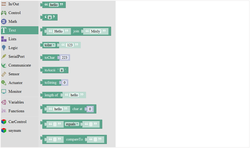
Text Block
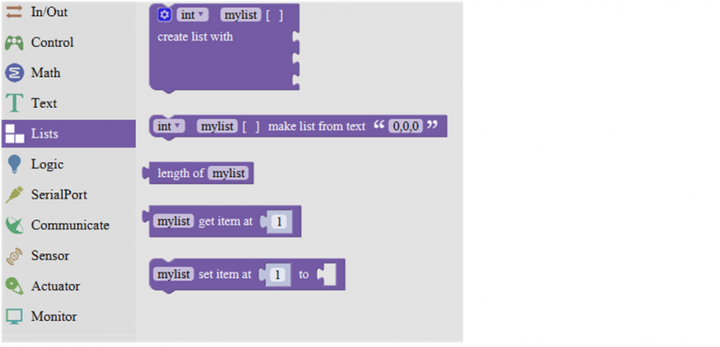
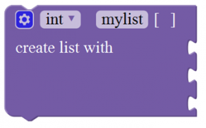
List Block
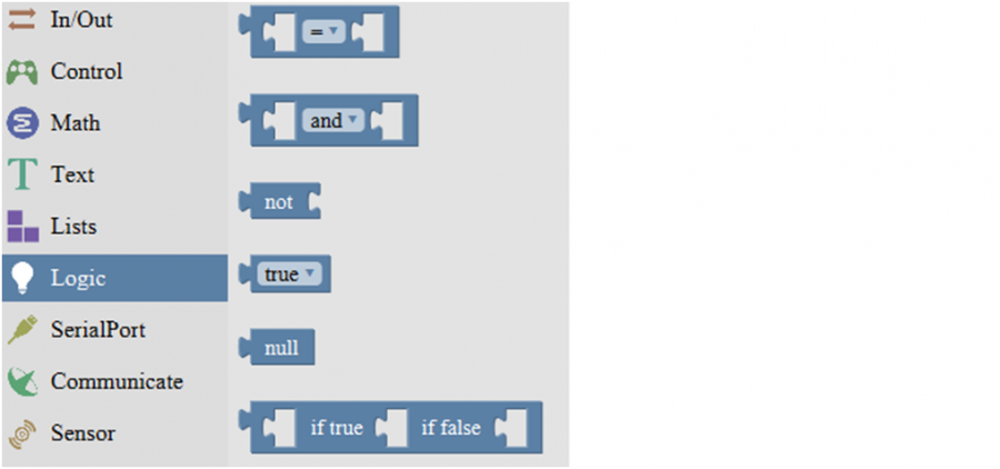
Logic Block
Variable Block
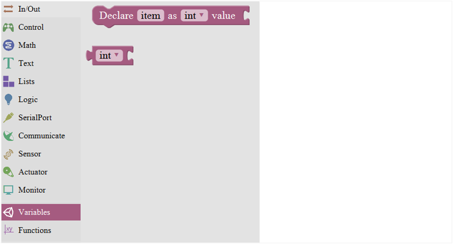
| No. | BLOCK ICON | DEFINITION |
|---|---|---|
| 1 |  |
Declare and initialize a variable. |
| 2 |  |
Define the data types |
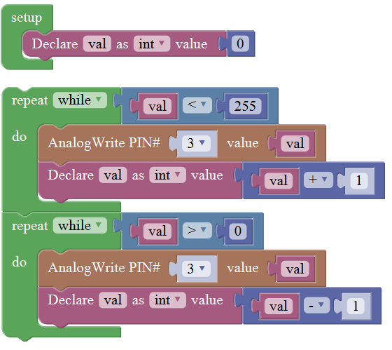
For example: LED breath
You need an Arduino Uno and one LED module. Connect the control pin of LED module to Pin 3 of Uno board (or other pins with “~”,that is, those pins can output PWM signal). LED will gradually light then gradually dim, repeatedly.
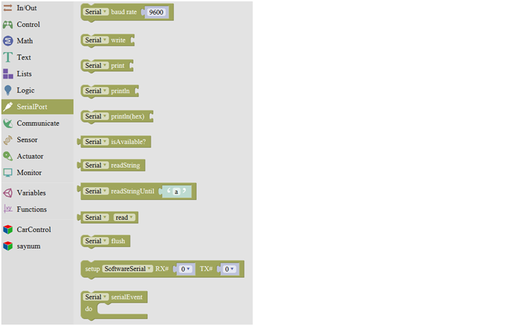
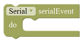
SerialPort Block
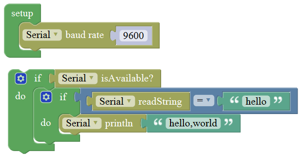
For example: serial communication
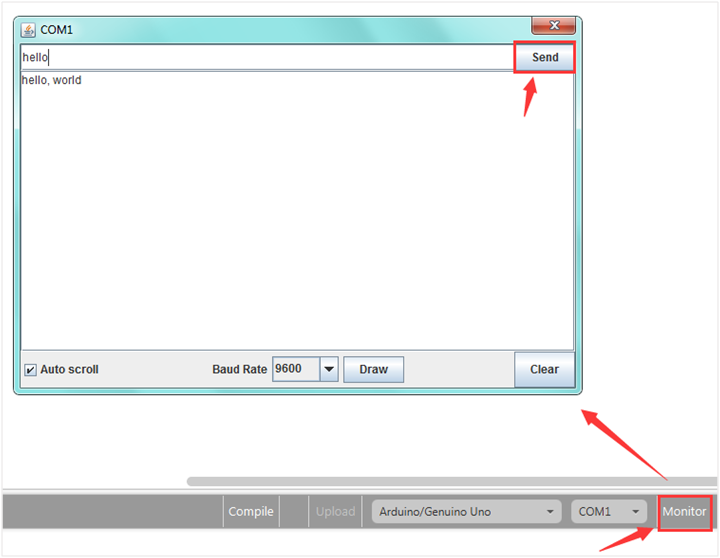
Done uploading the code, open the Arduino monitor, then enter a “hello” on the top bar, and click Send, it will print out “hello,world”.
Communicate Block
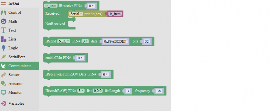
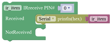
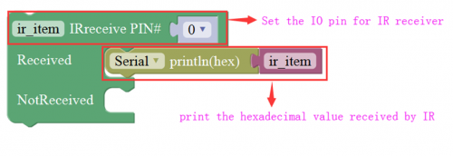
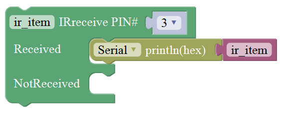
For example:
You need an Arduino Uno board, an IR receiver module and an IR remote control.
Connect the signal pin of IR receiver to Digital pin 3 of Uno board, then upload the code and open the monitor. If send a signal to an IR receiver module using an IR remote control, you should see the monitor show the corresponding signal data.
Sensor Block
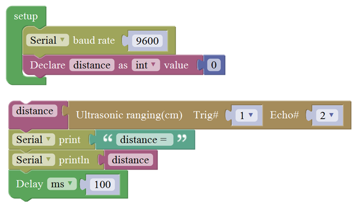
For example: ultrasonic ranging
Connect the Trig pin of ultrasonic sensor to Digital 1 of Uno, Echo pin to D2, then upload the code and open the monitor, you should see the distance value, updating once per 100ms.
Actuator Block
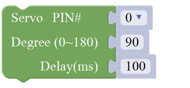
For example:
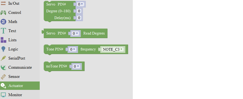
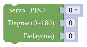
Connect the signal end of servo to Digital 0 of Uno, then upload the code below, servo will rotate 90 degrees.
Note: Delay 100ms is the time required for servo to move.
Monitor Block
For example: serial communication
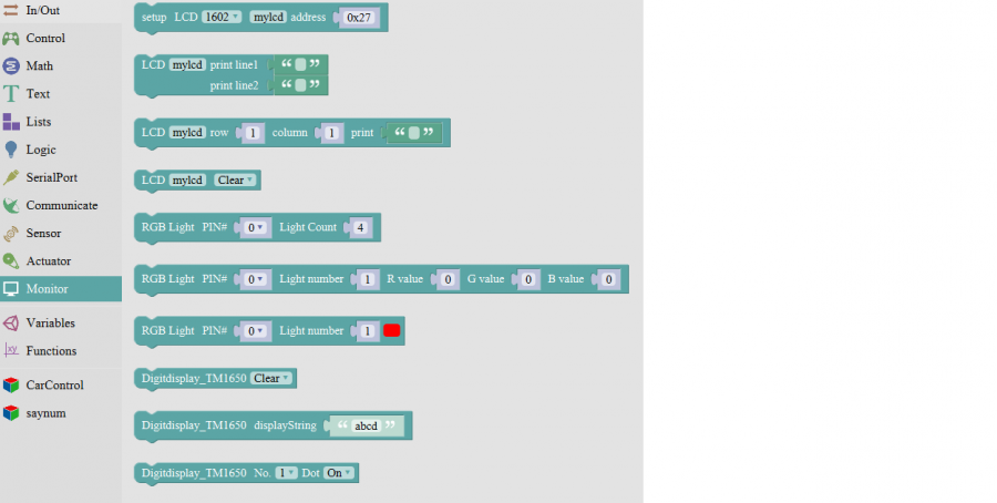
Separately connect the SDA (A4) and SCL (A5) of Arduino Uno to SDA and SCL pins of IIC LCD1602, then set the address of your LCD1602 screen, the LCD address we used here is 0x27. Then upload the code, LCD screen has two lines, you should see the line 1 print HELLO, and line 2 print 123456789.
Functions Block
For example: ultrasonic ranging
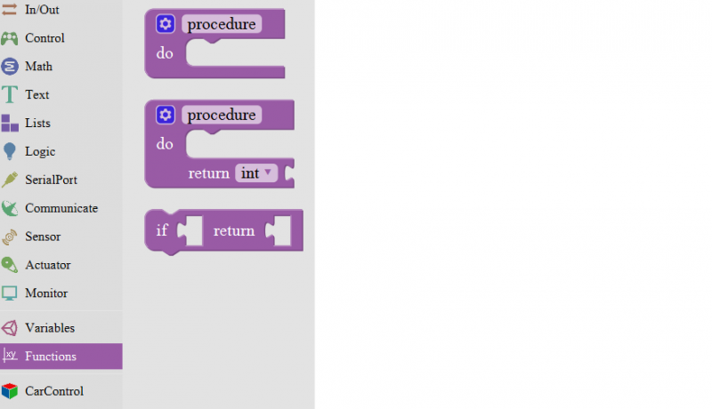
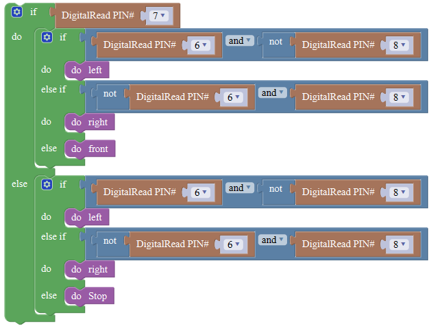
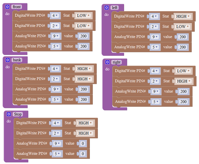
Below is an example code for line tracking car. We use three tracking modules (left to D6, middle to D7, right to D8). of course you need a tracking car to test it. First edit the forward, backward, turn left, turn right and stop into functions block. Then compile and upload the code below.
Installing Arduino Software
When you get the control board, first you should install the Arduino software and driver. We usually use the software Arduino 1.5.6 version.
You can download it from the link below:
https://www.arduino.cc/en/Main/OldSoftwareReleases#1.5.x
Or you can browse the ARDUINO website to download the latest version from this link, https://www.arduino.cc, pop up the following interface.
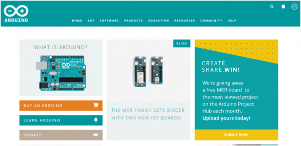
Then click the SOFTWARE on the browse bar, you will have two options ONLINE TOOLS and DOWNLOADS.
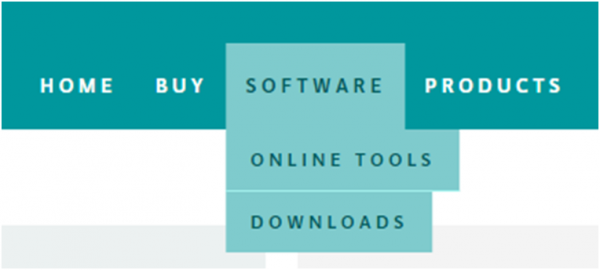
Click DOWNLOADS, it will appear the latest software version of ARDUINO 1.8.5 shown as below.
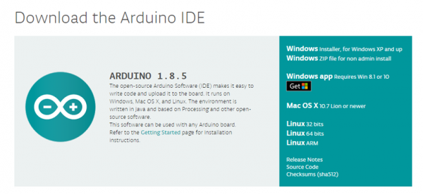
In this software page, on the right side you can see the version of development software for different operating systems. ARDUINO has a powerful compatibility. You should download the software that is compatible with the operating system of your computer.
We will take WINDOWS system as an example here. There are also two options under Windows system, one is installed version, the other is non-installed version.
For simple installed version, first click Windows Installer, you will get the following page.
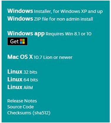

This way you just need to click JUST DOWNLOAD, then click the downloaded file to install it.
For non-installed version, first click Windows ZIP file, you will also get the pop-up interface as the above figure.
Click JUST DOWNLOAD, and when the ZIP file is downloaded well to your computer, you can directly unzip the file and click the icon of ARDUINO software to start it.
Installing Arduino (Windows)
Install Arduino with the exe. Installation package downloaded well.
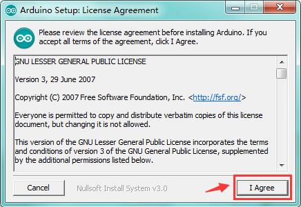
Click“I Agree”to see the following interface.
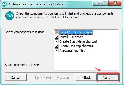
Click “Next”. Pop up the interface below.
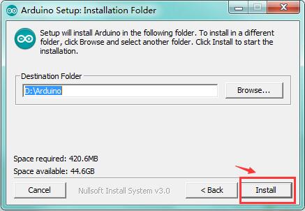
You can press Browse… to choose an installation path or directly type in the directory you want.
Then click “Install” to initiate installation.
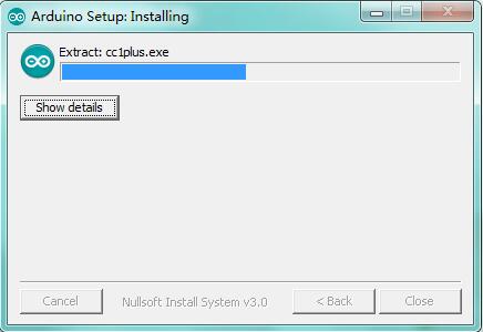
Wait for the installing process, if appear the interface of Window Security, just continue to click Install to finish the installation.
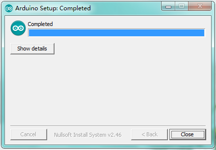
Installing Driver
Next, we will introduce the driver installation of UNO R3 development board. The driver installation may have slight differences in different computer systems. So in the following let’s move on to the driver installation in the WIN 7 system.
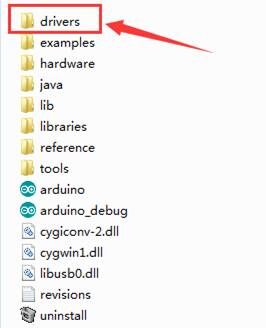
The Arduino folder contains both the Arduino program itself and the drivers that allow the Arduino to be connected to your computer by a USB cable. Before we launch the Arduino software, you are going to install the USB drivers.
Plug one end of your USB cable into the Arduino and the other into a USB socket on your computer.
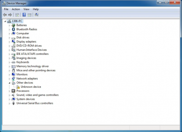
When you connect UNO board to your computer at the first time, right click the icon of your “Computer” —>for “Properties”—> click the “Device manager”, under “Other Devices”, you should see an icon for “Unknown device” with a little yellow warning triangle next to it. This is your Arduino.
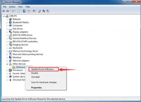
Then right-click on the device and select the top menu option (Update Driver Software...) shown as the figure below..
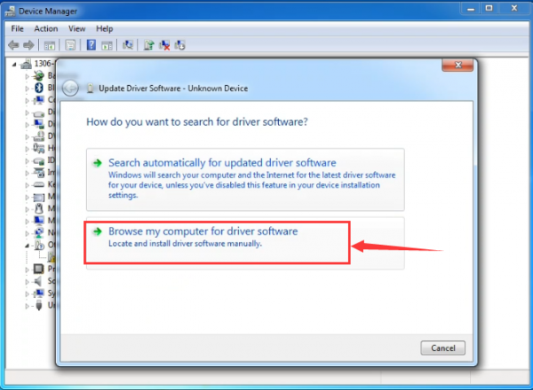
It will then be prompted to either “Search Automatically for updated driversoftware” or “Browse my computer for driver software”. Shown as below. In this page, select “Browse my computer for driver software”.
After that, select the option to browseand navigate to the “drivers” folder of Arduino installation.
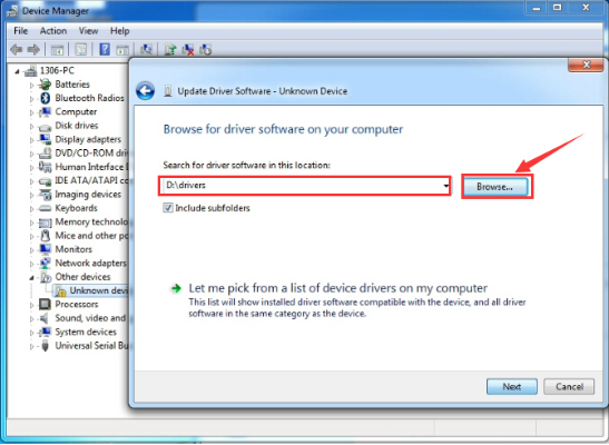
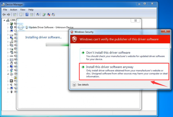
Click “Next” and you may get a security warning, if so, allow the software to be installed. Shown as below.
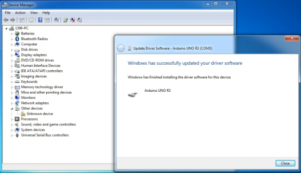
Once the software has been installed, you will get a confirmation message. Installation completed, click “Close”.
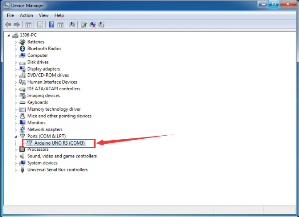
Up to now, the driver is installed well. Then you can right click “Computer” —>“Properties”—>“Device manager”, you should see the device as the figure shown below.
Let’s Get Started With Your Projects
Project 1: Hello World
Overview This project is very simple. You can use only a main board and a USB cable to display the “Hello World!”. It is a communication experiment between the EASY Plug control board and PC. This is an entry experiment for you to enter the Arduino programming world. Note that need to use a serial communication software, Arduino IDE. In the above part, you can check the detailed use of Arduino IDE.
Component Required:
- EASY plug control board*1
- USB cable*1
Component Introduction:
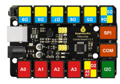
The processor used in keyestudio EASY plug control board V2.0 is ATmega328. It has 5 single Digital ports labeled D5 to D9 (of which 3 can be used as PWM outputs), 1 dual-digital interface (D3-D4), 4 analog inputs (A0-A3), a Joystick socket (D2-A6-A7), a SPI, a serial port and an IIC communication interface. Also with a USB connection, a power jack, two ICSP headers and a reset button. It breaks out the IO ports with RJ11 6P6C plug.
Connect It Up
Connect the control board to your computer via a micro USB cable.
Upload the Code
Below is an example code for displaying the Hello World!
int val;
int ledpin=13;
void setup()
{
Serial.begin(9600);
pinMode(ledpin,OUTPUT);
}
void loop()
{
val=Serial.read();
if(val=='R')
{
digitalWrite(ledpin,HIGH);
delay(500);
digitalWrite(ledpin,LOW);
delay(500);
Serial.println("Hello World!");
}
}
Select the Arduino Board
Open the Arduino IDE, you’ll need to click the “Tools”, then select the Board that corresponds to your Arduino.

Select your serial port
Select the serial device of the Arduino board from the Tools | Serial Port menu.
Note: to avoid errors, the COM Port should keep the same as the Ports shown on Device Manager.
