Ks0399(400, 401) keyestudio 37 in 1 Sensor V2.0 Kit for Arduino: Difference between revisions
Keyestudio (talk | contribs) No edit summary |
Keyestudio (talk | contribs) |
||
| Line 551: | Line 551: | ||
'''Sample Code''' | '''Sample Code''' | ||
<pre> | |||
Copy and paste the below code to Arduino software. | Copy and paste the below code to Arduino software. | ||
int redled =5; // initialize digital pin 5. | int redled =5; // initialize digital pin 5. | ||
int yellowled =4; // initialize digital pin 4. | int yellowled =4; // initialize digital pin 4. | ||
| Line 579: | Line 579: | ||
digitalWrite(redled, LOW);// turn off red LED | digitalWrite(redled, LOW);// turn off red LED | ||
} | } | ||
</pre> | |||
'''Experiment Result''' | '''Experiment Result''' | ||
Done uploading the code, powered up, three LEDs on the module will automatically simulate the traffic light on and off, alternatively. | Done uploading the code, powered up, three LEDs on the module will automatically simulate the traffic light on and off, alternatively. | ||
<br>[[Image:ks0399 Result3.png|600px|frameless]]<br> | <br>[[Image:ks0399 Result3.png|600px|frameless]]<br> | ||
===Project 4: Push Button=== | ===Project 4: Push Button=== | ||
Revision as of 11:31, 12 February 2019
-Sensor kit for Arduino
-Based on open-source hardware
-37 kinds of sensors in one box
-For you to make interesting projects
Kit Introduction
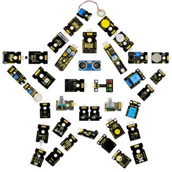
This is an Arduino 37 in 1 sensor learning kit developed by Keyestudio. You will have a set of Arduino's most common and useful electronic sensors and modules.
Inside this box, there are digital and analog sensors, and also some special modules such as ultrasonic, Joystick, relay, acceleration modules, etc.
For each module, there is clear connection diagram and sample code. So even if you are totally new at this, you can get started easily.
The sample codes for this sensor kit are based on ARDUINO because it's open source and easy. And if you are good at this, you can also apply this kit to other MCU development platform, such as 51, STM32, Raspberries Pi. The working principle is pretty much the same.
You may learn about Arduino from basic projects to more complex projects. Now, let us embrace this fascinating world of ARDUINO and learn together!
Kit List
Note: KS0399 kit with no board; KS0401 kit with UNO R3; KS0402 with 2560 MEGA R3
| No. | Product Name | Quantity | Picture |
|---|---|---|---|
| 1 | White LED module | 1 |  |
| 2 | RGB LED module | 1 | 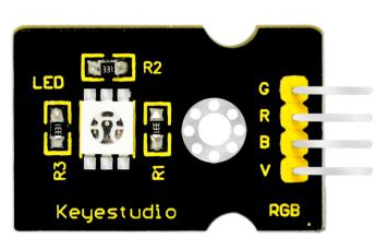 |
| 3 | Traffic light module | 1 | 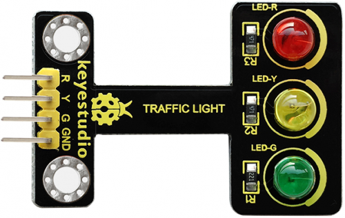 |
| 4 | Button switch module | 1 | 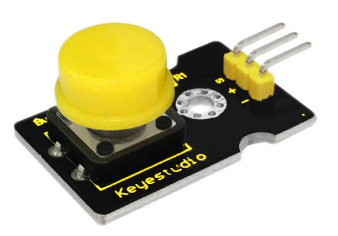 |
| 5 | Passive buzzer module | 1 | 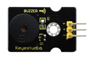 |
| 6 | Capacitive touch module | 1 | 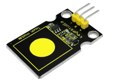 |
| 7 | Crash sensor | 1 | 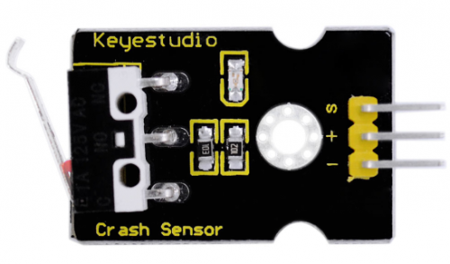 |
| 8 | Knock sensor | 1 | 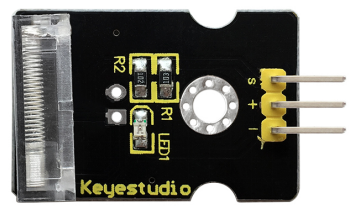 |
| 9 | Photo interrupter module | 1 | 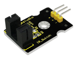 |
| 10 | Ball Tilt switch sensor | 1 | 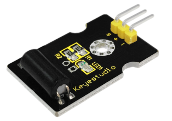 |
| 11 | PIR motion sensor | 1 | 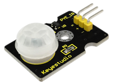 |
| 12 | Reed switch module | 1 | 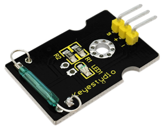 |
| 13 | Hall magnetic sensor | 1 | 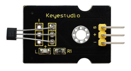 |
| 14 | Line tracking sensor | 1 | 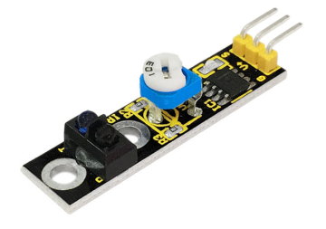 |
| 15 | Flame Sensor | 1 | 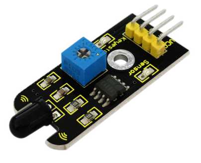 |
| 16 | Obstacle avoidance sensor | 1 | 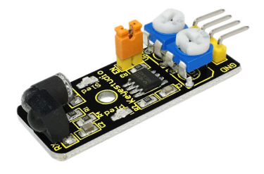 |
| 17 | Photo-resistor sensor | 1 | 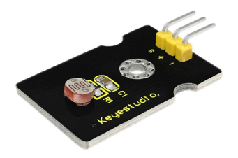 |
| 18 | Microphone sound sensor | 1 | 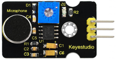 |
| 19 | Rotary encoder sensor | 1 | 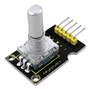 |
| 20 | MQ2 gas sensor | 1 | 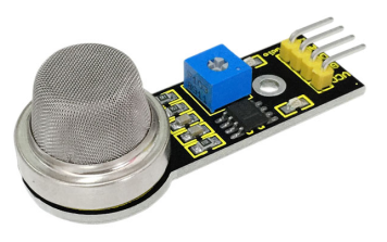 |
| 21 | Steam sensor | 1 | thumb |
| 22 | TEMT 6000 sensor | 1 | 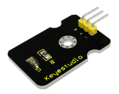 |
| 23 | LM35 temperature sensor | 1 | 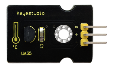 |
| 24 | DHT11 Temperature and Humidity Sensor | 1 | 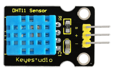 |
| 25 | EASY plug 2812 2x2 full-color RGB Module | 1 | 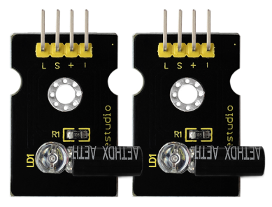 |
| 26 | IR receiver module | 1 | thumb |
| 27 | IR transmitter module | 1 | thumb |
| 28 | Ceramic vibration sensor | 1 | thumb |
| 29 | GUVA-S12SD 3528 Ultraviolet Sensor | 1 | 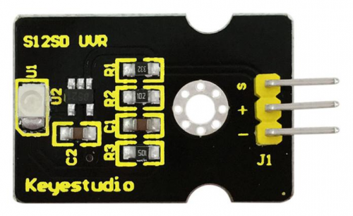 |
| 30 | MMA8452Q Module Acceleration Tilt Sensor | 1 | 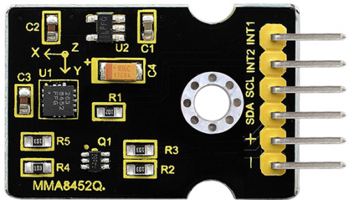 |
| 31 | TMD27713 sensor
ALS Infrared LED Optical Proximity Detection Module |
1 | 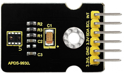 |
| 32 | APDS-9930 Attitude Sensor Module | 1 | 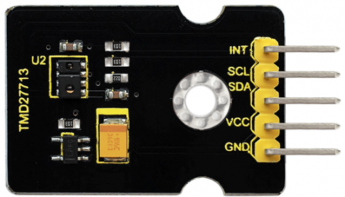 |
| 33 | Potentiometer sensor | 1 | 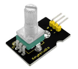 |
| 34 | DS3231 Clock module | 1 | 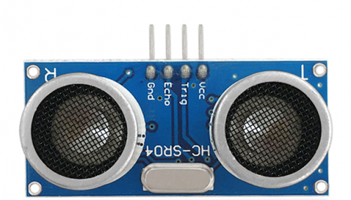 |
| 35 | Joystick module | 1 | thumb |
| 36 | Single relay module | 1 | thumb |
| 37 | HC-SR04 ultrasonic sensor | 1 | thumb |
Getting Started with Arduino
Installing Arduino Software
When you get the UNO development board, first you should install the Arduino software and driver.
We usually use the Windows software Arduino 1.5.6 version. You can download it from the link below:
https://www.arduino.cc/en/Main/OldSoftwareReleases#1.5.x
Or you can browse the ARDUINO website to download the latest version from this link, https://www.arduino.cc, pop up the following interface.
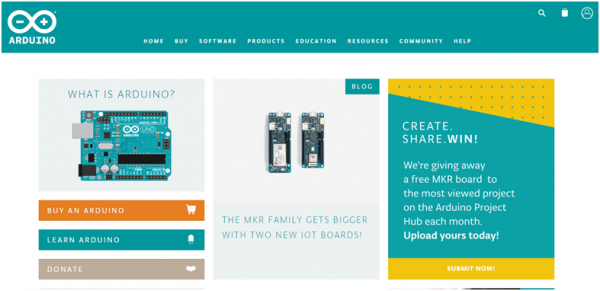
Then click the SOFTWARE on the browse bar, you will have two options ONLINE TOOLS and DOWNLOADS.

Click DOWNLOADS, it will appear the latest software version of ARDUINO 1.8.5 shown as below.
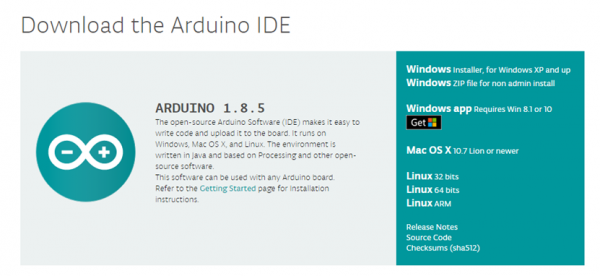
In this software page, on the right side you can see the version of development software for different operating systems. ARDUINO has a powerful compatibility. You should download the software that is compatible with the operating system of your computer.
We will take WINDOWS system as an example here. There are also two options under Windows system, one is installed version, the other is non-installed version.
For simple installed version, first click Windows Installer, you will get the following page.
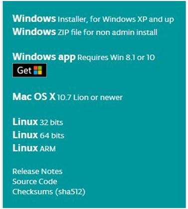

This way you just need to click JUST DOWNLOAD, then click the downloaded file to install it.
For non-installed version, first click Windows ZIP file, you will also get the pop-up interface as the above figure.
Click JUST DOWNLOAD, and when the ZIP file is downloaded well to your computer, you can directly unzip the file and click the icon of ARDUINO software to start it.
Installing Arduino (Windows)
Install Arduino with the exe. Installation package. Here we provide you with Arduino-1.5.6-r2-windows package, you can directly click the icon to install it.

Click“I Agree”to see the following interface.
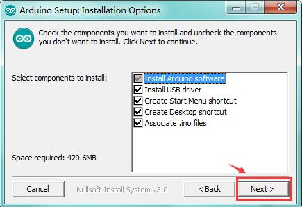
Click “Next”. Pop up the interface below.
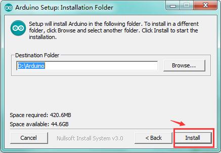
You can press Browse… to choose an installation path or directly type in the directory you want.
Then click “Install” to initiate installation.
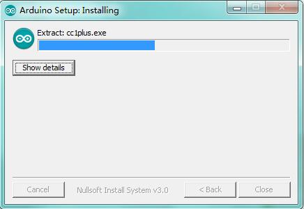
Wait for the installing process, if appear the interface of Window Security, just continue to click Install to finish the installation.
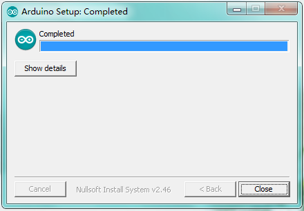
All right, up to now, you have completed the Arduino setup! The following icon will appear on your PC desktop.
Double-click the icon of Arduino to enter the desired development environment shown as below.
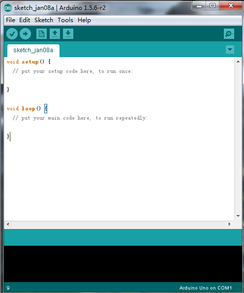
The functions of each button on the Toolbar are listed below:
![]()
Installing Driver
Next, we will introduce the driver installation for development board. The driver installation may have slight differences in different computer systems. So in the following let’s move on to the driver installation in the WIN 7 system.
The Arduino folder contains both the Arduino program itself and the drivers that allow the Arduino to be connected to your computer by a USB cable. Before we launch the Arduino software, you are going to install the USB drivers.
Plug one end of your USB cable into the Arduino and the other into a USB socket on your computer.
When you connect the UNO board to your computer at the first time, right click the icon of your “Computer” —>for “Properties”—> click “Device manager”, under “Other Devices”, you should see an icon for “Unknown device” with a little yellow warning triangle next to it. This is your Arduino.
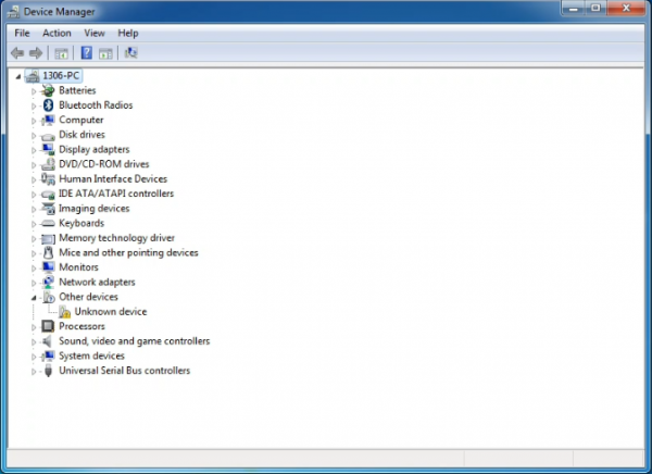
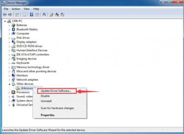
Then right-click on the device and select the top menu option (Update Driver Software...) shown as the figure below..
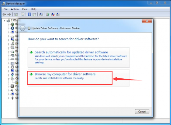
It will then be prompted to either “Search Automatically for updated driversoftware” or “Browse my computer for driver software”. Shown as below. In this page, select “Browse my computer for driver software”.
After that, select the option to browseand navigate to the “drivers” folder of Arduino installation.
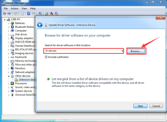
Click “Next” and you may get a security warning, if so, allow the software to be installed. Shown as below.

Once the software has been installed, you will get a confirmation message. Installation completed, click “Close”.

Up to now, the driver is installed well. Then you can right click “Computer” —>“Properties”—>“Device manager”, you should see the device as the figure shown below.
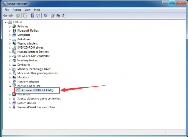
Example Use: Displaying Hello World
Overview
It is very simple. You can use only a main board and a USB cable to display the “Hello World!”. It is a communication experiment between the control board and PC. This is an entry experiment for you to enter the Arduino programming world.
Note that need to use a serial communication software, Arduino IDE.
In the above part, you can check the detailed use of Arduino IDE.
Component Required
- UNO R3 control board*1
- USB cable*1
Component Introduction
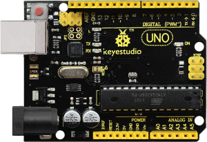
Keyestudio UNO R3 development board is a microcontroller board based on the ATmega328P (datasheet), fully compatible with ARDUINO UNO REV3. It has 14 digital input/output pins (of which 6 can be used as PWM outputs), 6 analog inputs, a 16 MHz quartz crystal, a USB connection, a power jack, 2 ICSP headers and a reset button.
It contains everything needed to support the microcontroller; simply connect it to a computer with a USB cable or power it with a AC-to-DC adapter or battery to get started.
Connect It Up
Connect the UNO board to your computer using the USB cable. The green power LED should go on.
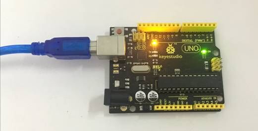
Upload the Code
Below is an example code for displaying the Hello World!
int val;
int ledpin=13;
void setup()
{
Serial.begin(9600);
pinMode(ledpin,OUTPUT);
}
void loop()
{
val=Serial.read();
if(val=='R')
{
digitalWrite(ledpin,HIGH);
delay(500);
digitalWrite(ledpin,LOW);
delay(500);
Serial.println("Hello World!");
}
}
Select the Arduino Board
Open the Arduino IDE, you’ll need to click the “Tools”, then select the Board that corresponds to your Arduino.
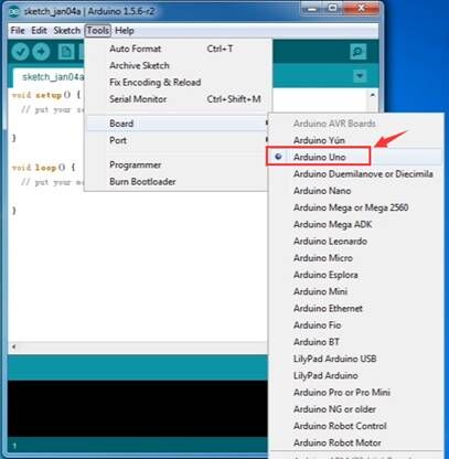
Select your serial port
Select the serial device of the Arduino board from the Tools | Serial Port menu.
Note: to avoid errors, the COM Port should keep the same as the Ports shown on Device Manager.
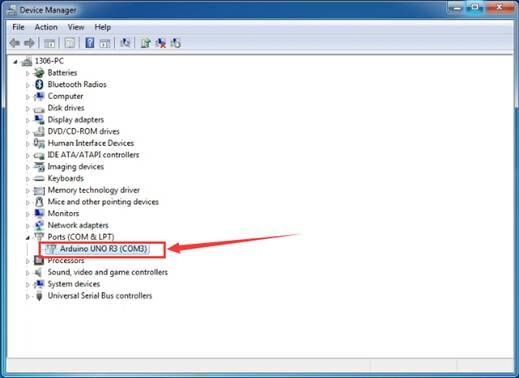

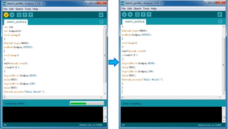
Then click verify button to check the errors. If compiling successfully, the message "Done compiling." will appear in the status bar.
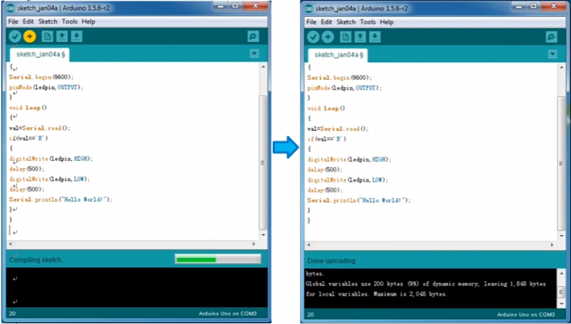
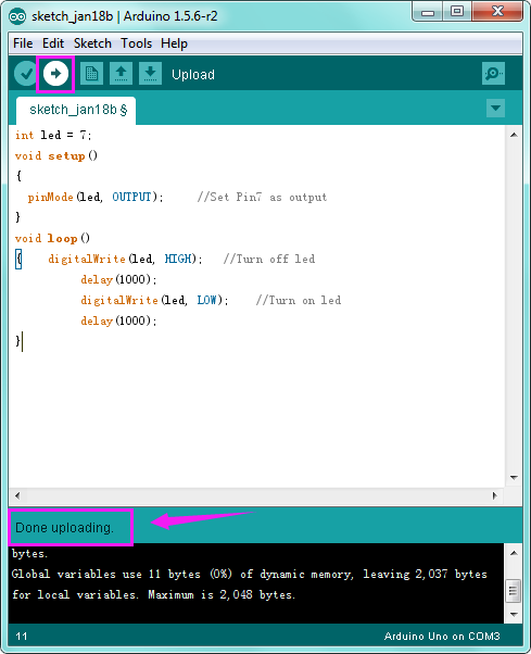
After that, click the “Upload” button to upload the code. Wait a few seconds - you should see the RX and TX leds on the board flashing. If the upload is successful, the message "Done uploading." will appear in the status bar.
(Note: If you have an Arduino Mini, NG, or other board, you'll need to physically present the reset button on the board immediately before pressing the upload button.)
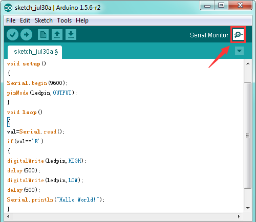
Open the Serial Monitor
After that, click the serial monitor button to open the serial monitor.
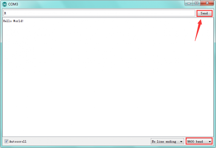
Then set the baud rate as 9600, enter an “R” and click Send, you should see the RX led on the board blink once, and then D13 led blink once, finally "Hello World!" is showed on the monitor, and TX led blink once.
Congrats! Your first simple program is complete.
Project Details
Project 1: LED Flash
Introduction LED has wide applications. Most signal lights we saw in our daily life use LED as its major light source. In today’s experiment, we are going to use Arduino to make LED module flashing.
Components list
- Arduino UNO * 1
- LED module * 1
- Jumper wire *3
Components Introduction
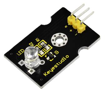
This is a special LED module. When you connect it to ARDUINO development board, after program, it can emit beautiful light. Of course, you can also control it using PWM. It will be like fireflies at night. Isn’t cool? We can also combine it with other sensors to do interesting interactive experiments.
Specifications
- Control interface: Digital
- Operating voltage: DC 3.3-5V
- Pin pitch:2.54mm
- Emitting color: white
Hardware Connection
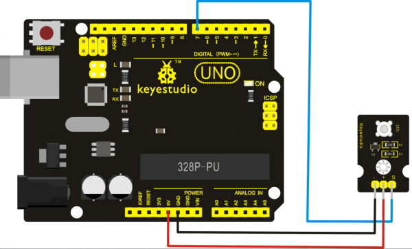
Connect the negative pin of LED module to GND, positive pin to VCC (3.3-5V), Signal pin to digital pin 7.
Sample Code
int led = 7;
void setup()
{
  pinMode(led, OUTPUT);     //Set Pin7 as output
}
void loop()
{    digitalWrite(led, HIGH);   //Turn off led
          delay(1000);
          digitalWrite(led, LOW);    //Turn on led
          delay(1000);
}
Experiment Result
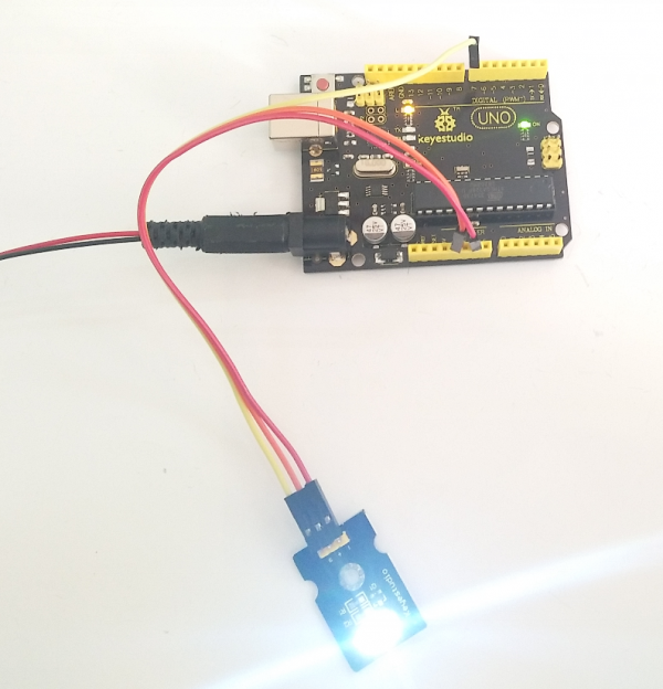
Done uploading the code, you can see the LED on the module flashing for one second then off for one second, repeatedly.
If it is not, go back and check your operations.
Project 2: RGB LED
Introduction This is a full-color LED module, which contains 3 basic colors-red, green and blue. They can be seen as separate LED lights. After program, we can turn them on and off by sequence. We can also use PWM analog output to mix the three colors to generate different colors.
Specification
- Color: red, green and blue
- Brightness: High
- Voltage: 5V
- Input: digital level
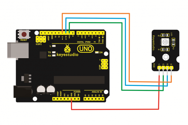
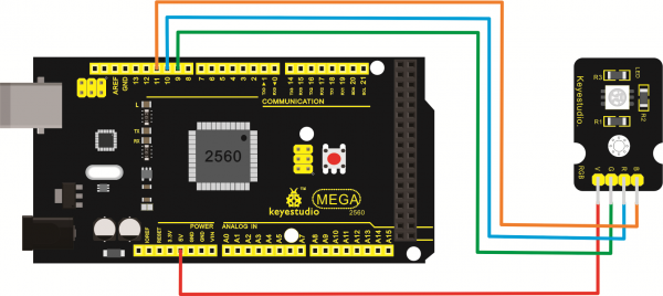
Hardware Connection To begin with, you need to prepare the following parts before connection:
- Arduino Board*1
- RGB LED module *1
- USB Cable*1
- Jumper Wire*4
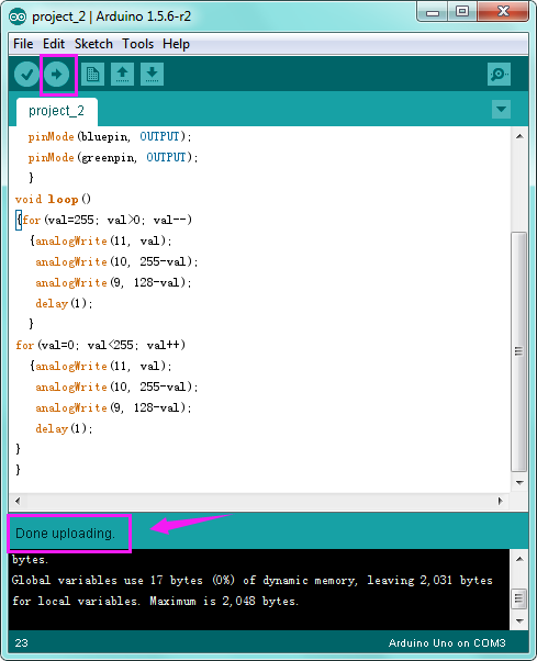
Sample Code
int redpin = 11; //select the pin for the red LED
int bluepin =10; // select the pin for the blue LED
int greenpin =9;// select the pin for the green LED
int val;
void setup() {
  pinMode(redpin, OUTPUT);
  pinMode(bluepin, OUTPUT);
  pinMode(greenpin, OUTPUT);
  }
void loop()
{for(val=255; val>0; val--)
  {analogWrite(11, val);
   analogWrite(10, 255-val);
   analogWrite(9, 128-val);
   delay(1);
  }
for(val=0; val<255; val++)
  {analogWrite(11, val);
   analogWrite(10, 255-val);
   analogWrite(9, 128-val);
   delay(1);
}
}
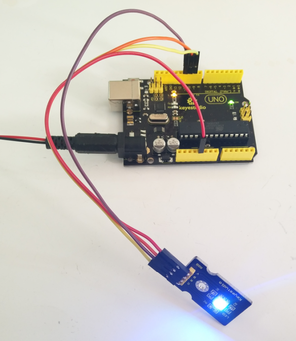
Experiment Result
You can see the RGB LED flashing in various colors.
Project 3: Traffic Light
Description When learning the microcontroller, you may usually use three LEDs, namely red, green and yellow lights to simulate the traffic light blinking via external connection. This time we specially design this module which is very convenient for wiring, and on the module you can see the red, yellow and green LED. This traffic light module is fully compatible with Arduino microcontroller and Raspberry Pi system.
Specifications
- Working Voltage: 3.3-5V
- Interface Type: digital
- Pin Pitch: 2.54mm
Hardware Connection First, you need to prepare the following parts before connection:
- Arduino Board*1
- Traffic light module *1
- USB Cable*1
- Jumper Wire*4
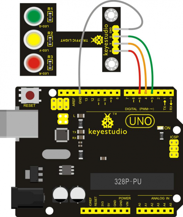
Connect the R pin of module to Digital 5 of UNO board, connect the Y pin to Digital 4, G pin to Digital 3, GND pin to ground port.
Sample Code
Copy and paste the below code to Arduino software.
int redled =5; // initialize digital pin 5.
int yellowled =4; // initialize digital pin 4.
int greenled =3; // initialize digital pin 3.
void setup()
{
pinMode(redled, OUTPUT);// set the pin with red LED as “output”
pinMode(yellowled, OUTPUT); // set the pin with yellow LED as “output”
pinMode(greenled, OUTPUT); // set the pin with green LED as “output”
}
void loop()
{
digitalWrite(greenled, HIGH);//// turn on green LED
delay(5000);// wait 5 seconds
digitalWrite(greenled, LOW); // turn off green LED
for(int i=0;i<3;i++)// blinks for 3 times
{
delay(500);// wait 0.5 seconds
digitalWrite(yellowled, HIGH);// turn on yellow LED
delay(500);// wait 0.5 seconds
digitalWrite(yellowled, LOW);// turn off yellow LED
}
delay(500);// wait 0.5 seconds
digitalWrite(redled, HIGH);// turn on red LED
delay(5000);// wait 5 seconds
digitalWrite(redled, LOW);// turn off red LED
}
Experiment Result
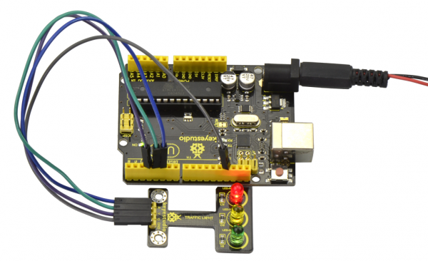
Done uploading the code, powered up, three LEDs on the module will automatically simulate the traffic light on and off, alternatively.
Project 4: Push Button
Introduction This is a basic application module integrated with a push button. You can simply plug it into an IO shield to have your first taste of Arduino.
Advantages
- Wide voltage range from 3.3V to 5V
- Interface: Digital
- Standard assembling structure
- Icons illustrate sensor function clearly
- High quality pin
- Easy to plug and operate
- Large button keypad and high-quality button cap
- Achieve interesting and interactive work
Components Introduction
Momentary Push button Switch
This is a common component for controlling electronic devices. It is mostly used to connect or cut off control circuit so that it can achieve motor or other electronic equipment control.
Momentary Pushbutton Switch usually stays open. When it is pressed down, circuit connected; when it is released, it will bounce back to the status of disconnection.
Momentary Pushbutton Switch has 4 footers which can be divided into 2 groups: footer 1 short connected with footer 2, footer 3 short connected with footer 4.
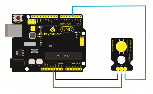
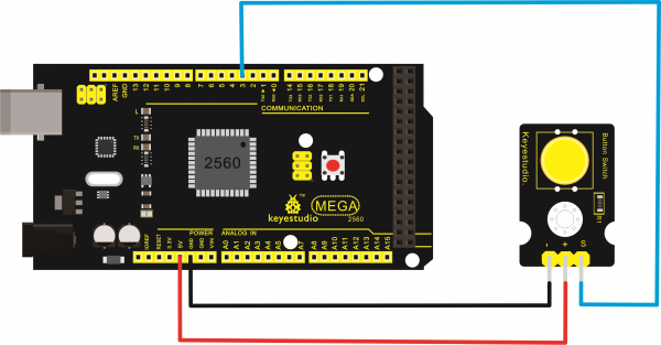
Hardware Connection
To begin with, you need to prepare the following parts:
- Arduino Board *1
- Button module *1
- USB Cable *1
- Jumper Wire *3
Sample Code
/* # When you push the digital button, the Led 13 will turn on. Otherwise, the led turns off.
*/
int ledPin = 13;                // choose the pin for the LED
int inputPin = 3;               // Connect sensor to input pin 3
void setup() {
  pinMode(ledPin, OUTPUT);      // declare LED as output
  pinMode(inputPin, INPUT);     // declare pushbutton as input
}
void loop(){
  int val = digitalRead(inputPin);  // read input value
  if (val == HIGH) {            // check if the input is HIGH
    digitalWrite(ledPin, LOW);  // turn LED OFF
  } else {
    digitalWrite(ledPin, HIGH); // turn LED ON
  }
}
Experiment Result
Done uploading the code, powered up, when you push the digital button, the Led 13 on UNO board will be on. When release the button, the led is off. Shown as below.
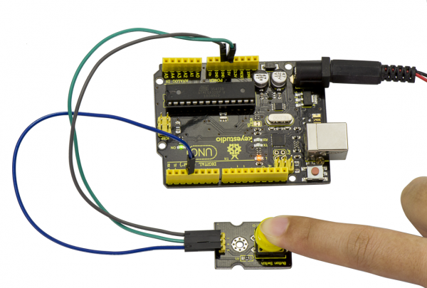
Think: '
If we want to connect more an LED module, light an LED when press down the button, and turn off LED when release the button, then how to program? You can have a try.
Project 5: Passive Buzzer
Introduction
We can use Arduino to make many interactive works of which the most commonly used is acoustic-optic display.
All the previous experiment has something to do with LED. However, the circuit in this experiment can produce sound. Normally, the experiment is done with a buzzer or a speaker while buzzer is simpler and easier to use.
The buzzer we introduced here is a passive buzzer. It cannot be actuated by itself, but by external pulse frequencies. Different frequencies produce different sounds. We can use Arduino to code the melody of a song, which is quite fun and simple.
Specification
- Working voltage: 3.3-5v
- Interface type: digital
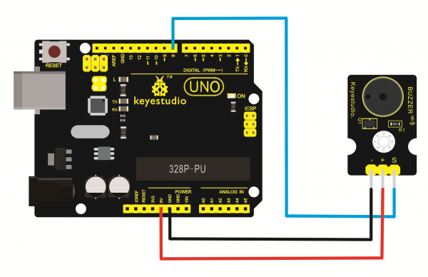
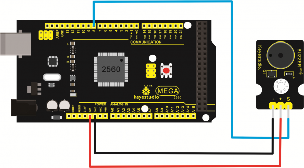
Hardware Connection
To begin with, you need to prepare the following parts:
- Arduino Board *1
- Passive buzzer module *1
- USB Cable *1
- Jumper Wire *3
Sample Code
int buzzer=3;//set digital IO pin of the buzzer
void setup()
{
pinMode(buzzer,OUTPUT);// set digital IO pin pattern, OUTPUT to be output
}
void loop()
{ unsigned char i,j;//define variable
while(1)
{ for(i=0;i<80;i++)// output a frequency sound
{ digitalWrite(buzzer,HIGH);// sound
delay(1);//delay1ms
digitalWrite(buzzer,LOW);//not sound
delay(1);//ms delay
}
for(i=0;i<100;i++)// output a frequency sound
{
digitalWrite(buzzer,HIGH);// sound
digitalWrite(buzzer,LOW);//not sound
delay(2);//2ms delay
}
}
}
Experiment Result
After downloading the program, buzzer experiment is complete. You should hear the buzzer ringing.
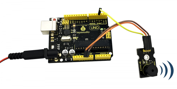
Project 6: Capacitive Touch
Introduction Are you tired of clicking mechanic button? Well, try our capacitive touch sensor. We can find touch sensors mostly on electronic device. So upgrade your Arduino Project with our new version touch sensor and make it cool!! This little sensor can "feel" people and metal touch and feedback a high/low voltage level. Even isolated by some cloth and paper, it can still feel the touch. Its sensitivity decrease as isolation layer gets thicker.
Specification
- Supply Voltage: 3.3V to 5V
- Interface: Digital
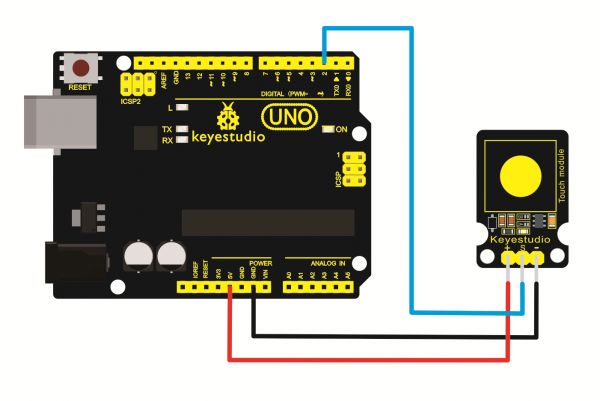
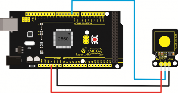
Hardware Connection
To begin with, you need to prepare the following parts:
- Arduino Board *1
- Capacitive touch sensor module *1
- USB Cable *1
- Jumper Wire *3
Sample Code
/* # When you push the digital button, the Led 13 will turn on. Otherwise, the led turns off.
*/
int ledPin = 13;                // choose the pin for the LED
int inputPin = 3;               // Connect sensor to input pin 3
void setup() {
  pinMode(ledPin, OUTPUT);      // declare LED as output
  pinMode(inputPin, INPUT);     // declare pushbutton as input
}
void loop(){
  int val = digitalRead(inputPin);  // read input value
  if (val == HIGH) {            // check if the input is HIGH
    digitalWrite(ledPin, LOW);  // turn LED OFF
  } else {
    digitalWrite(ledPin, HIGH); // turn LED ON
  }
}
Experiment Result
Done uploading the code, powered up, when you push the digital button, the Led 13 on UNO board will be on. When release the button, the led is off. Shown as below.
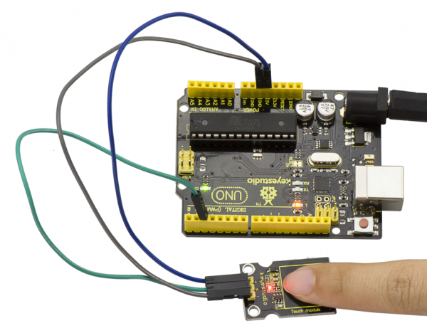
Think: '
If we want to connect more an LED module, light an LED when press down the button, and turn off LED when release the button, then how to program? You can have a try.
Project 7: Passive Buzzer
Introduction
Crash sensor, also known as electronic switch, is a digital on-off input module necessary for elementary electronic learning. By programming, it can realize to control over light, sound device, key choice function of LCD display, etc.
You can install the sensor to 4WD mobile robot platform to realize crash detection function. It is indeed convenient and efficient.
Details 1. If collision happens upfront of where collision module is installed, module outputs low level signal; no collision, outputs high level signal. 2. Module reserves M3 mounting hole, convenient for fixation on a car. 4. With switch indicator light, if there is collision, light is on; no collision, light is off.
Pins definition
- Positive pin (+): connect to 3v-12v power supply
- Negative pin (-): connect to GND
- Signal pin (S): connect to High-Low level output
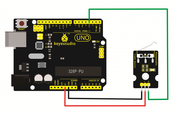
Hardware Connection To begin with, you need to prepare the following parts:
- Arduino Board *1
- Crash module *1
- USB Cable *1
- Jumper Wire *3
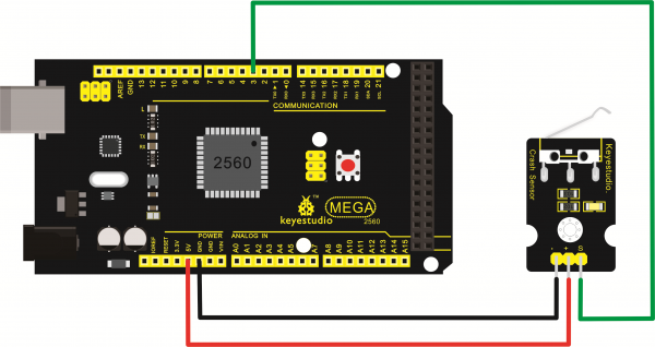
Note: 'You can make a collision flasher using collision module and built-in LED on interface 13. Connect the collision sensor to Digital pin 3. When the crash sensor senses a collision signal, the LEDs on both Arduino board and crash sensor will light up simultaneously.
Sample Code
Copy and paste the below code to Arduino software.
int Led=13;// set pin for LED
int Shock=3// set pin for collision sensor
;int val;// set digital variable val
void setup()
{
pinMode(Led,OUTPUT);// set pin LED as output
pinMode(Shock,INPUT);// set collision sensor as input
}
void loop()
{
val=digitalRead(Shock);// read value on pin 3 and assign it to val
if(val==HIGH)// when collision sensor detects a signal, LED turns on.
{
digitalWrite(Led,LOW);
} else
{
digitalWrite(Led,HIGH);
}
}
Experiment Result
Upload the code to the board.
When an object crashes the switch of sensor, both the led on the sensor and led 13 on the UNO board are turned on.
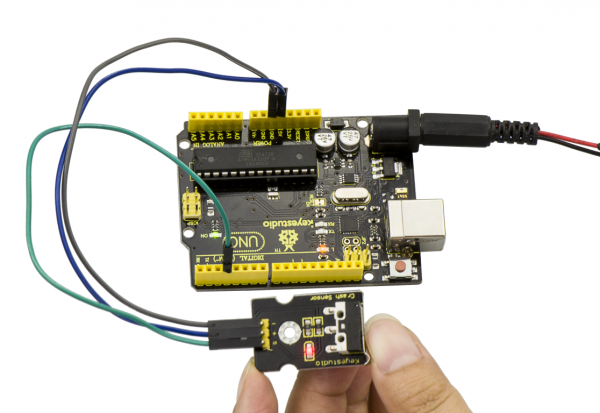
Project 8: Knock Sensor
Introduction This is a knock sensor module. When you knock it, it can send a momentary signal. We can combine it with Arduino to make some interesting experiment, e.g. electronic drum. Note: the working voltage of this module is 5V.
Hardware Connection To begin with, you need to prepare the following parts:
- Arduino Board *1
- Knock sensor module *1
- USB Cable *1
- Jumper Wire *3
Connect the S pin to digital 3, negative pin to GND port, positive pin to 5V port.
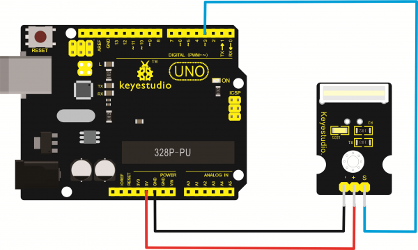
For 2560 R3 connection:
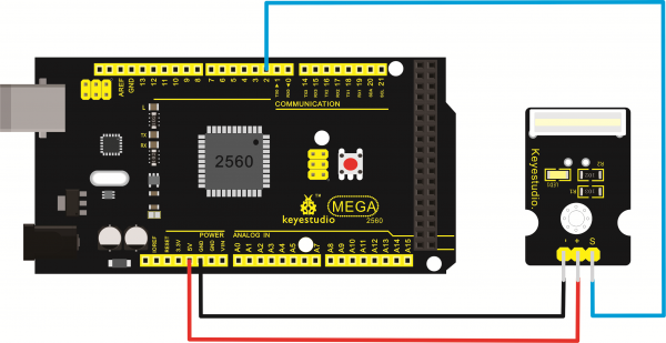
Sample Code
Copy and paste the below code to Arduino software.
int Led=13;//define LED interface
int Shock=3;//define knock sensor interface
int val;//define digital variable val
void setup()
{
pinMode(Led,OUTPUT);//define LED to be output interface
pinMode(Shock,INPUT);//define knock sensor to be output interface
}
void loop()
{
val=digitalRead(Shock);//read the value of interface3 and evaluate it to val
if(val==HIGH)//when the knock sensor detect a signal, LED will be flashing
{
digitalWrite(Led,LOW);
}
else
{
digitalWrite(Led,HIGH);
}
}
Experiment Result
Upload the code to the board.
When the sensor detects a knock signal, both the led on the sensor and led 13 on the UNO board are turned on.
Think: '
If not easy to see the test result, you can connect an external LED module. Light an LED when knock the sensor, then how to program? Think about it.
Project 9: Photo Interrupter
Introduction Upright part of this sensor is an infrared emitter and on the other side, it’s a shielded infrared detector. By emitting a beam of infrared light from one end to other end, the sensor can detect an object when it passes through the beam. It is used for many applications including optical limit switches, pellet dispensing, general object detection, etc.
Specification
- Supply Voltage: 3.3V to 5V
- Interface: Digital
Hardware Connection To begin with, you need to prepare the following parts:
- Arduino Board *1
- Photo Interrupter module *1
- USB Cable *1
- Jumper Wire *3
Connect the S pin to digital 3, negative pin to GND port, positive pin to 5V port.
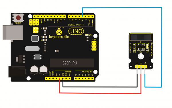
For 2560 R3 connection:
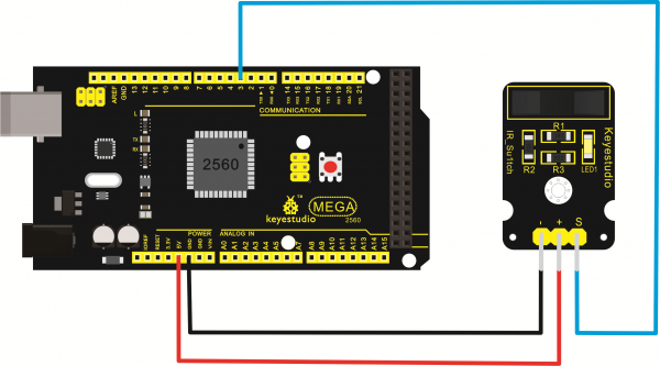
Sample Code
Copy and paste the below code to Arduino software.
// photo interrupter module
int Led = 13 ;// define LED Interface
int buttonpin = 3; // define the photo interrupter sensor interface
int val ;// define numeric variables val
void setup ()
{
  pinMode (Led, OUTPUT) ;// define LED as output interface
  pinMode (buttonpin, INPUT) ;// define the photo interrupter sensor output interface
}
void loop ()
{
  val = digitalRead (buttonpin) ;// digital interface will be assigned a value of 3 to read val
  if (val == HIGH) // When the light sensor detects a signal is interrupted, LED flashes
  {
    digitalWrite (Led, HIGH);
  }
  else
  {
    digitalWrite (Led, LOW);
  }
}
Experiment Result
Upload the code to the board. When an object passes through the groove joint of photo interrupter module, the signal is interrupted, led will flash.
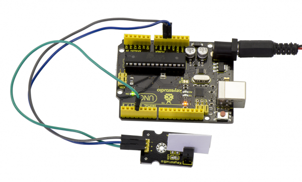
Think: '
If not easy to see the built-in led status, you can connect an external LED module, then how to program? Think about it.
Project 10: Digital Tilt Sensor
Introduction Tilt Sensor is a simple digital tilt switch. Simply plug it to our IO/Sensor shield or Arduino board, you can make interesting and interactive projects.
Tilt sensors (tilt ball switch) allow you to detect orientation or inclination. They are small, inexpensive, low-power and easy-to-use. If used properly, they will not wear out. Their simplicity makes them popular for toys, gadgets and appliances.
Sometimes, they are referred to as "mercury switches", "tilt switches" or "rolling ball sensors" for obvious reasons. They are usually made up of a cavity of some sort (cylindrical is popular, although not always) with a conductive free mass inside, such as a blob of mercury or rolling ball. One end of the cavity has two conductive elements (poles). When the sensor is oriented so that that end is downwards, the mass rolls onto the poles and shorts them, acting as a switch throw. While not as precise or flexible as a full accelerometer, tilt switches can detect motion or orientation. Another benefit is that the big ones can switch power on their own. Accelerometer, on the other hand, output digital or analog voltage that must then be analyzed using extra circuitry.
Specification
- Supply Voltage: 3.3V to 5V
- Interface: Digital
Hardware Connection To begin with, you need to prepare the following parts:
- Arduino Board *1
- Tilt ball switch module *1
- USB Cable *1
- Jumper Wire *3
Connect the S pin to digital 3, negative pin to GND port, positive pin to 5V port.
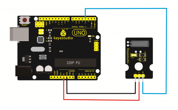
For 2560 R3 connection:
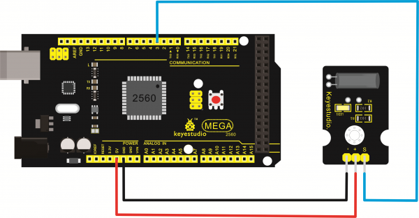
Sample Code
Copy and paste the below code to Arduino software.
int ledPin = 13;                // Connect LED to pin 13
int switcher = 3;                 // Connect Tilt sensor to Pin3
void setup()
{
  pinMode(ledPin, OUTPUT);      // Set digital pin 13 to output mode
  pinMode(switcher, INPUT);       // Set digital pin 3 to input mode
}
void loop()
{
   if(digitalRead(switcher)==HIGH) //Read sensor value
     {
        digitalWrite(ledPin, HIGH);   // Turn on LED when the sensor is tilted
     }
   else
     {
        digitalWrite(ledPin, LOW);    // Turn off LED when the sensor is not triggered
     }
}
Experiment Result
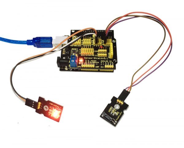
Upload the code to the board. Then tilt the sensor, you will see the led on the sensor is turned on. Shown as below.
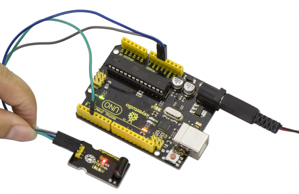
Think: '
Or you can connect more an external LED module, then how to program? Think about it. The LED will turn on when tilt the sensor, and the LED will turn off when the sensor is not tilted.
For example:
Project 11: PIR Motion Sensing
Introduction Pyroelectric infrared motion sensor can detect infrared signals from a moving person or moving animal, and output switching signals. It can be applied to a variety of occasions to detect the movement of human body. Conventional pyroelectric infrared sensors require body pyroelectric infrared detector, professional chip, complex peripheral circuit, so the size is bigger, with complex circuit, and lower reliability. Now we launch this new pyroelectric infrared motion sensor, specially designed for Arduino. It uses an integrated digital body pyroelectric infrared sensor, has smaller size, higher reliability, lower power consumption and simple peripheral circuit.
Specification
- Input Voltage: 3.3 ~ 5V, 6V Maximum
- Working Current: 15uA
- Working Temperature: -20 ~ 85 ℃
- Output Voltage: High 3V, low 0V
- Detection angle: 100 °
- Detection distance: 7 meters
- Output Indicator LED (When output HIGH, it will be ON)
- Pin limit current: 100mA
Hardware Connection
To begin with, you need to prepare the following parts:
- Arduino Board *1
- PIR motion sensor*1
- USB Cable *1
- Jumper Wire *3
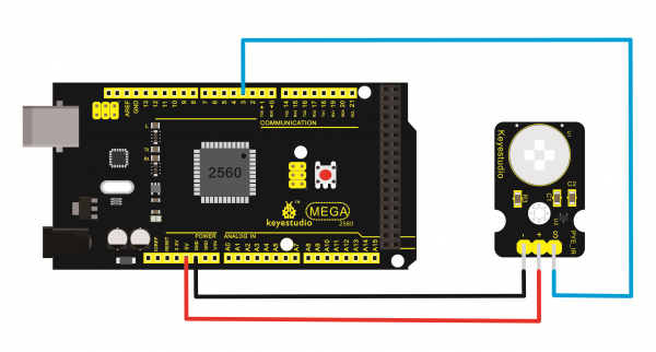
Connect the S pin to digital 3, negative pin to GND port, positive pin to 5V port.
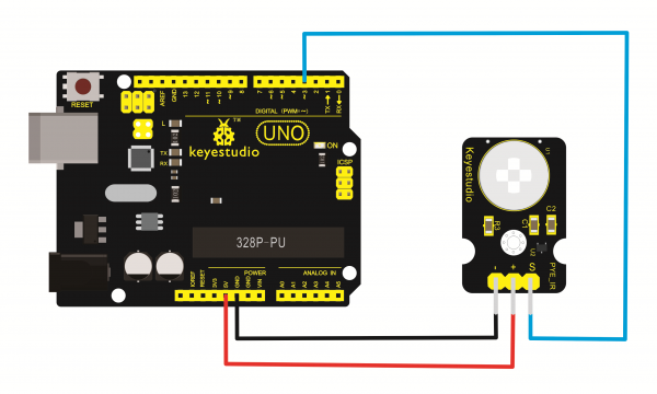
For 2560 R3 connection:
Sample Code
Copy and paste the below code to Arduino software.
byte sensorPin = 3;
byte indicator = 13;
void setup()
{
  pinMode(sensorPin,INPUT);
  pinMode(indicator,OUTPUT);
  Serial.begin(9600);
}
void loop()
{
  byte state = digitalRead(sensorPin);
  digitalWrite(indicator,state);
  if(state == 1)Serial.println("Somebody is in this area!");
  else if(state == 0)Serial.println("No one!");
  delay(500);
}
Experiment Result
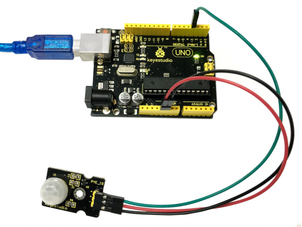
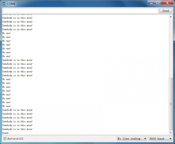
Done wiring and powered up, upload well the code, if the sensor detects someone moving nearby, D13 indicator on UNO board will light up, and "Somebody is in this area!" is displayed on the serial monitor.
If no detecting the movement, D13 indicator will turn off, and "No one!" is displayed on the serial monitor.
Project 12: Reed Switch
Description Reed Switch is a special switch and a main component for reed relay and proximity switch. Reed switch is usually comprised of two soft magnetic materials and metal reed contacts which will disconnect itself when there is no magnetic.
In addition, some reed switches are also equipped with another reed acting as the third normally-closed contact. These reed contacts are encapsulated in a glass tube fulled of inert gases(such as nitrogen and helium) or in a vacuum glass tube. The reeds encapsulated in the glass tube are placed in parallel with ends overlapped. Certain amount of space or mutual contact will be reserved to constitute the normally-open or normally-closed contacts of the switch.
Reed switch can be used as for count, limit or other purposes. For instance, a kind of bike-kilometer is constituted by sticking magnetic to the tire and mounting reed switch aside. You can also mount reed switch on the door for alarming purpose or as switches. Reed switch has been widely applied in household appliances, cars, communication, industry, healthcare and security areas. Furthermore, it can also be applied to other sensors and electric devices such as liquidometer, door magnet, reed relay, oil level sensor and proximity sensor(magnetic sensor). It can be used under high-risk environment.
Specification
- Working voltage: DC 3.3V-5V
- Working current: ≥20mA
- Working temperature: -10℃ to+50℃
- Detection distance: ≤10mm
- IO Interface: 3Pin (-/+/S)
Hardware Connection To begin with, you need to prepare the following parts:
- Arduino Board *1
- Reed switch sensor*1
- USB Cable *1
- Jumper Wire *3
Connect the S pin to digital 3, negative pin to GND port, positive pin to 5V port.

For 2560 R3 connection:

Sample Code
Copy and paste the below code to Arduino software.
int Led=13;//define LED interface
int buttonpin=3; //define magnetic ring sensor interface
int val;//define digital variable val
void setup()
{
pinMode(Led,OUTPUT);//define LED as output interface
pinMode(buttonpin,INPUT);//define magnetic ring sensor as output interface
 }
void loop()
{
val=digitalRead(buttonpin);// read and assign the value of digital interface 3 to val
if(val==HIGH)//When a signal is detected by magnetic ring sensor, LED will flash
{
digitalWrite(Led,HIGH);
}
else
{
digitalWrite(Led,LOW);
}
}
Experiment Result
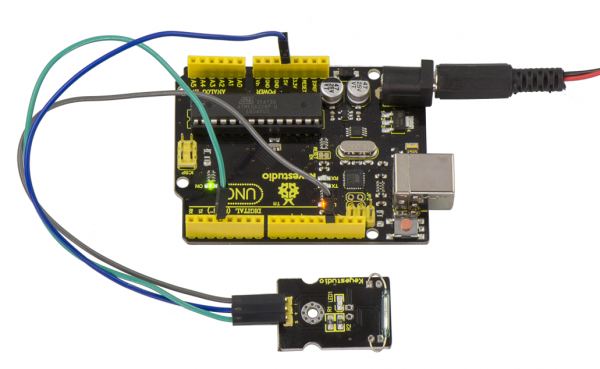
Done wiring and powered up, upload well the code to the board. You can see the D13 led on UNO board is on.
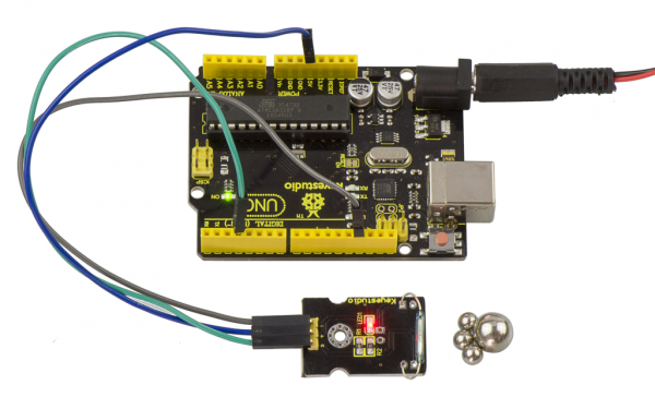
Then we put some magnetic balls close to the sensor. When the sensor detects the magnetic field signal, the led on the sensor will be turned on but D13 led will be turned off.
Project 13: Hall Magnetic Sensor
Introduction This is a Magnetic Induction Sensor. It senses the magnetic materials within a detection range up to 3cm. The detection range and the strength of the magnetic field are proportional. The output is digital on/off. This sensor uses the SFE Reed Switch - Magnetic Field Sensor.
Specification
- Sensing magnetic materials
- Detection range: up to 3cm
- Output: digital on/off
- Detection range and magnetic field strength are proportional
Hardware Connection To begin with, you need to prepare the following parts:
- Arduino Board *1
- Hall Magnetic sensor*1
- USB Cable *1
- Jumper Wire *3
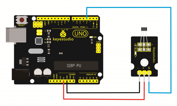
Connect the S pin to digital 3, negative pin to GND port, positive pin to 5V port.
For 2560 R3 connection:
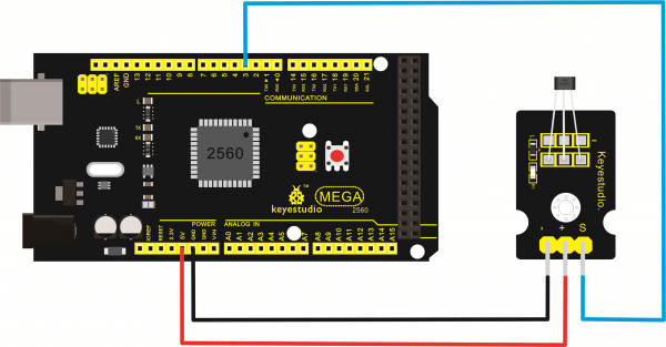
Sample Code
int ledPin = 13;                // choose the pin for the LED
int inputPin = 3;               // Connect sensor to input pin 3
int val = 0;                    // variable for reading the pin status

void setup() {
  pinMode(ledPin, OUTPUT);      // declare LED as output
  pinMode(inputPin, INPUT);     // declare pushbutton as input
}

void loop(){
  val = digitalRead(inputPin);  // read input value
  if (val == HIGH) {            // check if the input is HIGH
    digitalWrite(ledPin, LOW);  // turn LED OFF
  } else {
    digitalWrite(ledPin, HIGH); // turn LED ON
  }
}
Experiment Result
Wire it up and upload well the code to board, you will see that D13 indicator on UNO board is off, and led on the module is also off.
But if put a magnetic ball close to the hall module, you will see the D13 indicator on UNO board is turned on, and led on the module is also turned on.

Project 14: Line Tracking
Introduction This Line Tracking Sensor can detect white line in black and black line in white. The single line-tracking signal provides a stable output signal TTL for a more accurate and more stable line. Multi-channel option can be easily achieved by installing required line-tracking robot sensors.
Specification
- Power supply: +5V
- Operating current: <10mA
- Operating temperature range: 0°C ~ + 50°C
- Output interface: 3Pin interface (1 - signal, 2 - power, 3 - power supply negative)
- Output Level: TTL level
Hardware Connection To begin with, you need to prepare the following parts:
- Arduino Board *1
- Line tracking sensor*1
- USB Cable *1
- Jumper Wire *3
Connect the S pin to digital 3, negative pin to GND port, positive pin to 5V port.
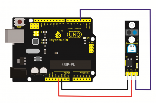
For 2560 R3 connection:
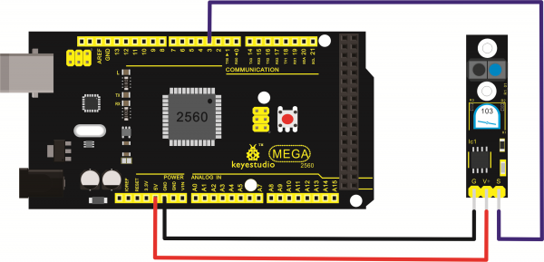
Sample Code
///Arduino Sample Code
void setup()
{
  Serial.begin(9600);
}
void loop()
{
  Serial.println(digitalRead(3)); // print the data from the sensor
  delay(500);
}
Experiment Result
Done uploading the code to board, open the serial monitor and set the baud rate to 9600, then you can see the data from the sensor. Shown below.

Project 15: Flame Sensor
Introduction This flame sensor can be used to detect fire or other lights whose wavelength stands at 760nm ~ 1100nm. In the fire-fighting robot game, the flame plays an important role in the probe, which can be used as the robot's eyes to find fire source.
Specification
- Supply Voltage: 3.3V to 5V
- Detection range: 20cm (4.8V) ~ 100cm (1V)
- Rang of Spectral Bandwidth: 760nm to 1100nm
- Operating temperature: -25℃ to 85℃
- Interface: digital
Hardware Connection To begin with, you need to prepare the following parts:
- Arduino Board *1
- Flame sensor*1
- USB Cable *1
- Jumper Wire *3
Connect the S pin to digital 2, negative pin to GND port, positive pin to 5V port.
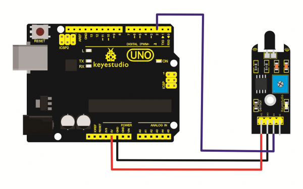
For 2560 R3 connection:
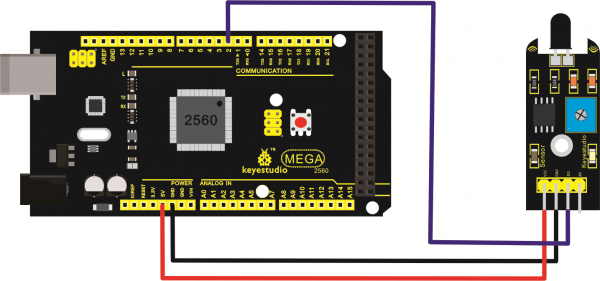
Sample Code
const int flamePin = 2;     // the number of the flame pin
const int ledPin =  13;      // the number of the LED pin
// variables will change:
int State = 0;         // variable for reading status
void setup() {
  // initialize the LED pin as an output:
  pinMode(ledPin, OUTPUT);
  // initialize the pushbutton pin as an input:
  pinMode(flamePin, INPUT);
}
void loop(){
  // read the state of the value:
State = digitalRead(flamePin);
  if (State == HIGH) {

    // turn LED on:
    digitalWrite(ledPin, HIGH);
  }
  else {
    // turn LED off:
    digitalWrite(ledPin, LOW);
  }
}
Experiment Result
Done wiring and powered up, upload well the code to the board.
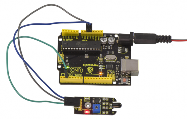
Then if you put a lighter close to the sensor, when the sensor detects the flame, another led on the sensor is turned on.
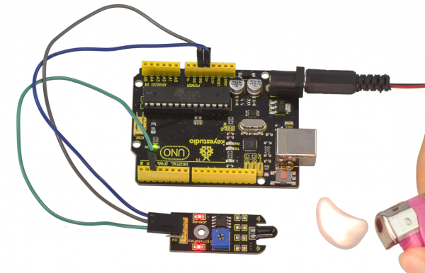
Project 16: Infrared Obstacle Avoidance
Introduction Infrared obstacle avoidance sensor is equipped with distance adjustment function and is especially designed for wheeled robots. This sensor has strong adaptability to ambient light and is of high precision. It has a pair of infrared transmitting and receiving tube. When infrared ray launched by the transmitting tube encounters an obstacle (its reflector), the infrared ray is reflected to the receiving tube, and the indicator will light up; the signal output interface outputs digital signal.
We can adjust the detection distance through the potentiometer knob (effective distance: 2~40cm, working Voltage: 3.3V-5V ). Thanks to a wide voltage range, this sensor can work steadily even under fluctuating power supply voltage and is suitable for the use of various micro-controllers, Arduino controllers and BS2 controllers. A robot mounted with the sensor can sense changes in the environment.
Specification
- Working voltage: DC 3.3V-5V
- Working current: ≥20mA
- Working temperature: -10℃—+50℃
- Detection distance: 2-40cm
- IO Interface: 4 wire interface (-/+/S/EN)
- Output signal: TTL voltage
- Accommodation mode: Multi-circle resistance regulation
- Effective Angle: 35°
Hardware Connection To begin with, you need to prepare the following parts:
- Arduino Board *1
- Infrared obstacle avoidance sensor*1
- USB Cable *1
- Jumper Wire *3
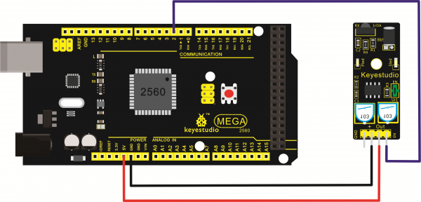
Connect the S pin to digital 2, negative pin to GND port, positive pin to 5V port.
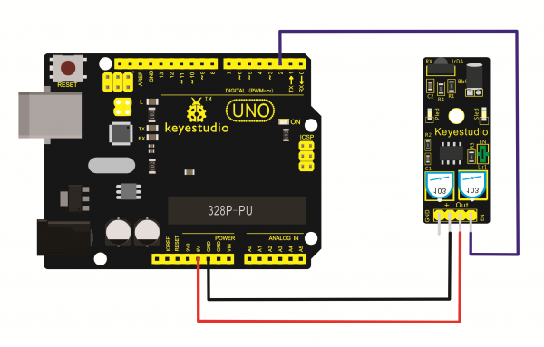
For 2560 R3 connection:
Sample Code
const int sensorPin = 2;     // the number of the sensor pin
const int ledPin =  13;      // the number of the LED pin
int sensorState = 0;         // variable for reading the sensor status
void setup() {
  pinMode(ledPin, OUTPUT);
  pinMode(sensorPin, INPUT); }
void loop(){
  // read the state of the sensor value:
  sensorState = digitalRead(sensorPin);
  // if it is, the sensorState is HIGH:
  if (sensorState == HIGH) {
     digitalWrite(ledPin, HIGH);
  }
  else {

       digitalWrite(ledPin, LOW);
  }
}
Experiment Result
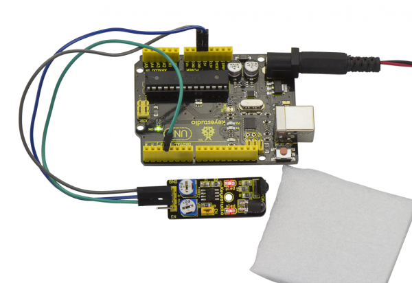
Done uploading the code to board, if we put a foam block in front of the sensor, this time when sensor detects the obstacle, sled on the sensor will be turned on.
Project 17 : Photocell sensor
Introduction Photocell is commonly seen in our daily life and is mainly used in intelligent switch, also in common electronic design. To make it easier and more effective, we supply corresponding modules. Photocell is a semiconductor. It has features of high sensitivity, quick response, spectral characteristic, and R-value consistence, maintaining high stability and reliability in environment extremes such as high temperature, high humidity.
It’s widely used in automatic control switch fields like cameras, garden solar lights, lawn lamps, money detectors, quartz clocks, music cups, gift boxes, mini night lights, sound and light control switches, etc.
Specification
- Interface type: analog
- Working voltage: 5V
Hardware Connection To begin with, you need to prepare the following parts:
- Arduino Board *1
- Photocell sensor*1
- USB Cable *1
- Jumper Wire *3
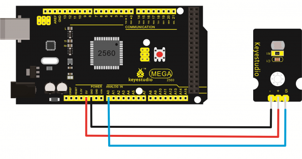
Connect the S pin to analog A0, negative pin to GND port, positive pin to 5V port.
Connect the S pin to digital 2, negative pin to GND port, positive pin to 5V port.
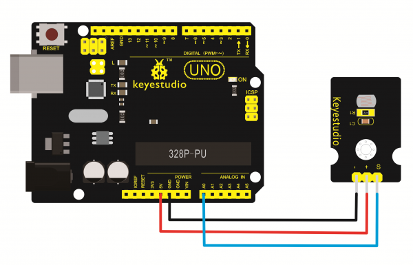
For 2560 R3 connection:
Sample Code
int sensorPin =A0 ;
int value = 0;
void setup()
{
 Serial.begin(9600); }
void loop()
{
 value = analogRead(sensorPin);
Serial.println(value, DEC);
delay(50); }
Experiment Result
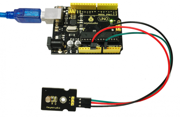
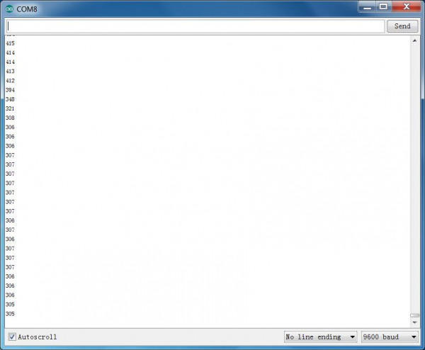
Done wiring and powered up, upload well the code, then open the serial monitor; if cover the photocell on the sensor with your hand, you will see the analog value decrease.
