Ks0495 keyestudio Micro bit Honeycomb Vibration & Tilt Module: Difference between revisions
Keyestudio (talk | contribs) No edit summary |
Keyestudio (talk | contribs) No edit summary |
||
| Line 1: | Line 1: | ||
[[image: | [[image:0495.png|thumb|450px|right|keyestudio Micro bit Honeycomb Vibration & Tilt Module ]] | ||
== Description == | == Description == | ||
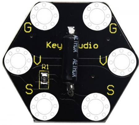
keyestudio micro bit honeycomb vibration tilt module is fully compatible with micro bit control board. | |||
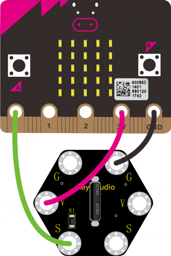
In the experiment, we connect it with the micro: bit by a crocodile clip. There are 6 sockets on it, 2 G, 2 V and 2 S are connected. Additionally, G is GND, VV is VCC, and S is the signal end of the module. | |||
The | Its function is to detect vibration and tilt. The SW-200D vibration switch element adopted on this module is a ball type tilt induction unidirectional trigger switch, one end of which is gold-plated(trigger end), another one is silver-plated (conductive end). | ||
When the module is in the horizontal position or inclined to the conductive end (silver-plated), the switch element is in OFF state and the signal end outputs the high level; when the module is tilted to the trigger terminal (gold-plated), the switch element is ON state, and the signal terminal outputs the low level. When the angle of the conductive end (silver-plated)is lower than 10 ° horizontally and the module is shaken by external force, so the trigger end (gold-plated) will be a short-time ON state; which makes the module detect vibration.<br> | |||
== Parameters == | == Parameters == | ||
* Working voltage: DC 3. | * Working voltage: DC 3.3-5V | ||
* Working current: 60mA | * Working current: 60mA | ||
* Maximum power: 300mW | * Maximum power: 300mW | ||
* Working temperature: -25 ℃ --65 ℃ | * Working temperature: -25 ℃ --65 ℃ | ||
* | * Size: 30mm * 27mm * 5mm | ||
* Weight: 2.0g | * Weight: 2.0g | ||
* Environmental attributes: ROHS | * Environmental attributes: ROHS | ||
== Connection Diagram == | == Connection Diagram == | ||
<br>[[image: | <br>[[image:0495-1.png|350px|frameless|thumb]]<br> | ||
== Test Code == | == Test Code == | ||
<br>[[File: | <br>[[File:0495-2.png|450px|frameless|thumb]]<br> | ||
== Test Result == | == Test Result == | ||
Wire according to connection diagram, upload the code successfully, open the serial monitor software( | Wire according to connection diagram, upload the test code successfully. | ||
After connecting the computer to power on with USB cable, open the serial monitor software (such as Arduino IDE) and set the baud rate to 115200. The value of S end will be shown on the monitor. When module tilts towards trigger end(gold-plated), the value is 0 at the signal S end, LED dot matrix of micro bit displays the pattern [[File:0495-3.png|300px|frameless|thumb]]; otherwise, when module tilts towards conductive end(silver-plated), the value is 1 at the signal S end, LED dot matrix of micro bit displays the pattern[[File:0495-4.png|300px|frameless|thumb]],as shown below. | |||
<br>[[File:0495-5.png|500px|frameless|thumb]]<br> | |||
When the angle of the conductive end (silver-plated) is lower than 10 °, the trigger end (gold-plated) will be a transitory ON state when the module is shaken. The value is 0 at the signal end S, LED dot matrix displays the pattern[[File:0495-3.png|300px|frameless|thumb]]。 | |||
Revision as of 09:26, 18 March 2020
Description
keyestudio micro bit honeycomb vibration tilt module is fully compatible with micro bit control board.
In the experiment, we connect it with the micro: bit by a crocodile clip. There are 6 sockets on it, 2 G, 2 V and 2 S are connected. Additionally, G is GND, VV is VCC, and S is the signal end of the module.
Its function is to detect vibration and tilt. The SW-200D vibration switch element adopted on this module is a ball type tilt induction unidirectional trigger switch, one end of which is gold-plated(trigger end), another one is silver-plated (conductive end).
When the module is in the horizontal position or inclined to the conductive end (silver-plated), the switch element is in OFF state and the signal end outputs the high level; when the module is tilted to the trigger terminal (gold-plated), the switch element is ON state, and the signal terminal outputs the low level. When the angle of the conductive end (silver-plated)is lower than 10 ° horizontally and the module is shaken by external force, so the trigger end (gold-plated) will be a short-time ON state; which makes the module detect vibration.
Parameters
- Working voltage: DC 3.3-5V
- Working current: 60mA
- Maximum power: 300mW
- Working temperature: -25 ℃ --65 ℃
- Size: 30mm * 27mm * 5mm
- Weight: 2.0g
- Environmental attributes: ROHS
Connection Diagram
Test Code
Test Result
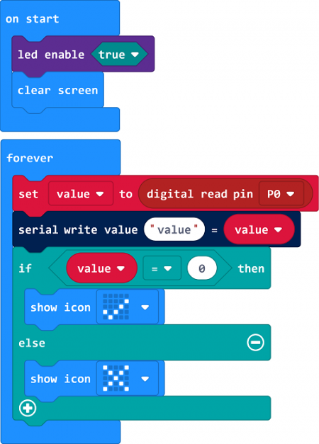
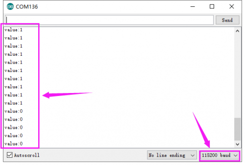
Wire according to connection diagram, upload the test code successfully. After connecting the computer to power on with USB cable, open the serial monitor software (such as Arduino IDE) and set the baud rate to 115200. The value of S end will be shown on the monitor. When module tilts towards trigger end(gold-plated), the value is 0 at the signal S end, LED dot matrix of micro bit displays the pattern thumb; otherwise, when module tilts towards conductive end(silver-plated), the value is 1 at the signal S end, LED dot matrix of micro bit displays the patternthumb,as shown below.
When the angle of the conductive end (silver-plated) is lower than 10 °, the trigger end (gold-plated) will be a transitory ON state when the module is shaken. The value is 0 at the signal end S, LED dot matrix displays the patternthumb。
Resources
- Download relevant code: https://drive.google.com/open?id=1xTBgf9FYeqNgDf9FpLOa8GBLGhSp0Pvu


