KS0095 KEYESTUDIO CNC Kit V3.0
Introduction
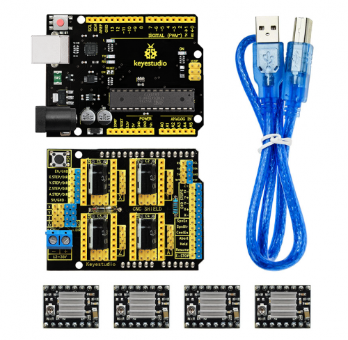
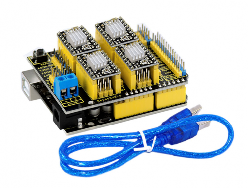
Keyestudio CNC Shield V3.0 can be used as driver expansion board for engraving machines . It has in total 4 channel slots for A4988 stepper motor driver modules (not included) for driving 4 channel of stepper motors. Each channel of stepper motor only needs 2 IO ports, which means 6 IO ports is sufficient to manage 3 stepper motors. This shield can make quick work for managing stepper motors in your project.
Specification
- Latest Keyestudio CNC Shield Version 3.0
- GRBL 0.8c compatible. (Open source firmware that runs on a keyestudio V4.0 board that turns G-code commands into stepper signals)
- 4-Axis support (X, Y, Z , A-Can duplicate X,Y,Z or do a full 4th axis with custom firmware using pins D12 and D13)
- 2 x End stops for each axis (6 in total)
- Spindle enable and direction
- Coolant enable
- Uses removable Pololu A4988 compatible stepper drivers. (A4988, DRV8825 and others)
- Jumpers to set the Micro-Stepping for the stepper drivers. (Some drivers like the DRV8825 can do up to 1/32 micro-stepping )
- Compact design.
- Stepper Motors can be connected with 4 pin molex connectors or soldered in place.
- Runs on 12V DC.
Kit List
- 1x Keyestudio CNC Shield V3.0
- 1x keyestudio V4.0 Board
- 4x A4988 Driver
- 1x USB Cable
Connection Diagram
Install Software and Development board driver
Download software
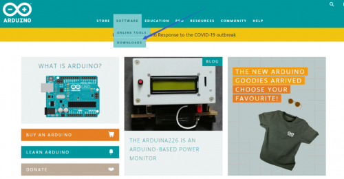
When we get control board, we need to download Arduino IDE and driver firstly. You could download Arduino IDE from the official website: https://www.arduino.cc/, click the SOFTWARE on the browse bar, click “DOWNLOADS” to enter download page, as shown below:
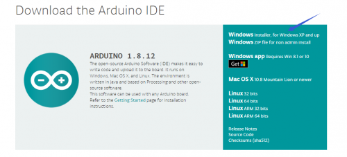
There are various versions for Arduino, just download a suitable version for your system, we will take WINDOWS system as an example to show you how to download and install.
There are two versions for WINDOWS system, one is installed version, another one is download version, you just need to download file to computer directly and unzip it. These two versions can be used normally. Choose one and download on your computer.
You just need to click JUST DOWNLOAD, then click the downloaded file to install it. And when the ZIP file is downloaded, you can directly unzip and start it.
Keyestudio V4.0 Development Board
We need to know keyestudio V4.0 development board, as a core of this smart car.
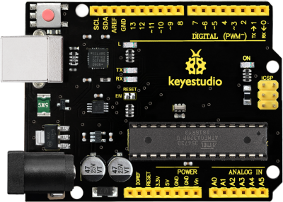
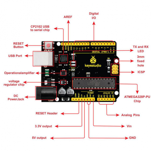
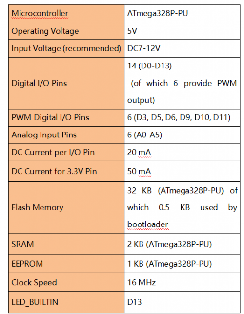
keyestudio V4.0 development board is an Arduino uno-compatible board, which is based on ATmega328P MCU, and with a cp2102 Chip as a UART-to-USB converter.
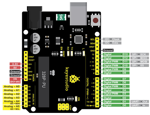
It has 14 digital input/output pins (of which 6 can be used as PWM outputs), 6 analog inputs, a 16 MHz quartz crystal, a USB connection, a power jack, 2 ICSP headers and a reset button.
It contains everything needed to support the microcontroller; simply connect it to a computer with a USB cable or power it via an external DC power jack (DC 7-12V) or via female headers Vin/ GND(DC 7-12V) to get started.
Installing driver
Let’s install the driver of keyestudio PLUS control board. The USB-TTL chip on PLUS board adopts CP2102 serial chip. The driver program of this chip is included in Arduino 1.8 version and above, which is convenient. Plug on USB port of board, the computer can recognize the hardware and automatically install the driver of CP2102.
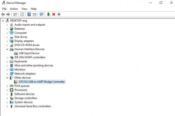
If install unsuccessfully, or you intend to install manually, open the device manager of computer. Right click Computer----- Properties----- Device Manager.
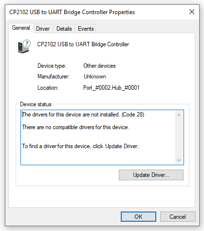
There is a yellow exclamation mark on the page, which implies installing the driver of CP2102 unsuccessfully. Then we double click the hardware and update the driver.
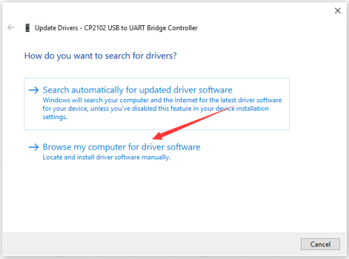
Click “OK” to enter the following page, click “browse my computer for updated driver software”, find out the installed or downloaded ARDUINO software. As shown below:
There is a DRIVERS folder in Arduino software installed package(![]() ), open driver folder and you can see the driver of CP210X series chips.
), open driver folder and you can see the driver of CP210X series chips.
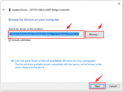
We click “Browse”, then find out the driver folder, or you could enter “driver” to search in rectangular box, then click “next”, the driver will be installed successfully. (I place Arduino software folder on the desktop, you could follow my way)
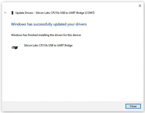
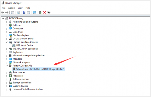
Open device manager, we will find the yellow exclamation mark disappear. The driver of CP2102 is installed successfully.
Arduino IDE Setting
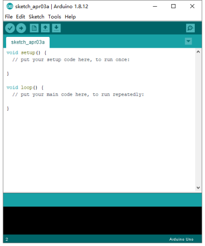
To avoid the errors when uploading the program to the board, you need to select the correct Arduino board that matches the board connected to your computer.
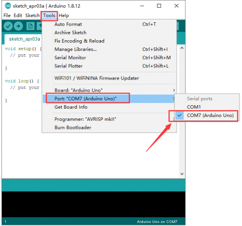
Then come back to the Arduino software, you should click Tools→Board, select the board. (as shown below)
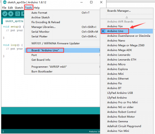
Then select the correct COM port (you can see the corresponding COM port after the driver is successfully installed)
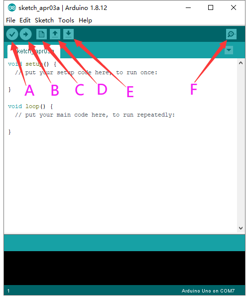
Before uploading the program to the board, let’s demonstrate the function of each symbol in the Arduino IDE toolbar.
A- Used to verify whether there is any compiling mistakes or not.
B- Used to upload the sketch to your Arduino board.
C- Used to create shortcut window of a new sketch.
D- Used to directly open an example sketch.
E- Used to save the sketch.
F- Used to send the serial data received from board to the serial monitor.
Using Method
(1)Test Main Board
First, write below code in IDE to test whether main board, shield and three motors work normally.
Explanation
1.If you properly reduce the value 800 in delayMicroseconds(800) to increase the frequency of input PWM signal, you can increase the rotation speed of stepper motor. The change of value cannot be too much or the motor will stop moving.
2. Rotate the knob on A4988, you can adjust the output current of the motors to change the torque.
Code:
*****************************************************************
#define EN        8       // stepper motor enable, low level effective
#define X_DIR     5       //X axis, stepper motor direction control
#define Y_DIR     6       //y axis, stepper motor direction control
#define Z_DIR     7       //zaxis, stepper motor direction control
#define X_STP     2       //x axis, stepper motor control
#define Y_STP     3       //y axis, stepper motor control
#define Z_STP     4       //z axis, stepper motor control
/*
// Function: step   -control the direction and number of steps of the stepper motor
// Parameter: dir  -direction control, dirPin corresponds to DIR pin, stepperPin corresponds to


step pin, steps is the number of steps.
// no return value
*/
void step(boolean dir, byte dirPin, byte stepperPin, int steps)
{
  digitalWrite(dirPin, dir);
  delay(50);
  for (int i = 0; i < steps; i++) {
    digitalWrite(stepperPin, HIGH);
    delayMicroseconds(800);
    digitalWrite(stepperPin, LOW);
    delayMicroseconds(800);
  }
}
void setup(){// set the IO pins for the stepper motors as output
  pinMode(X_DIR, OUTPUT); pinMode(X_STP, OUTPUT);
  pinMode(Y_DIR, OUTPUT); pinMode(Y_STP, OUTPUT);
  pinMode(Z_DIR, OUTPUT); pinMode(Z_STP, OUTPUT);
  pinMode(EN, OUTPUT);
  digitalWrite(EN, LOW);
}
void loop(){
  step(false, X_DIR, X_STP, 200); // x axis motor rotates CCW for 1 circle, as in 200 steps
  step(false, Y_DIR, Y_STP, 200); // y axis motor rotates CCW for 1 circle, as in 200 steps
  step(false, Z_DIR, Z_STP, 200); // z axis motor rotates CCW for 1 circle, as in 200 steps
  delay(1000);
  step(true, X_DIR, X_STP, 200); // X axis motor rotates CW for 1 circle, as in 200 steps
  step(true, Y_DIR, Y_STP, 200); // y axis motor rotates CW for 1 circle, as in 200 steps
  step(true, Z_DIR, Z_STP, 200); // z axis motor rotates CW for 1 circle, as in 200 steps
  delay(1000);
}
*****************************************************************

(2)Install Firmware and Grbl Controller
a. Write test program to keyestudio V4.0 board
copy the folder GRBL_ Arduino_Library_keyes in the data packet  and paste it to the folder libraries in your Arduino IDE document installation.

Code:
***********************************************
#include <grblmain.h>
void setup(){
startGrbl();
}
void loop(){}
//Burn the code above to keyestudio V4.0 board
***********************************************
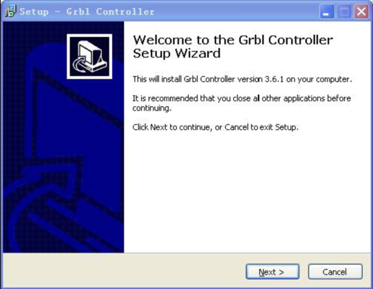
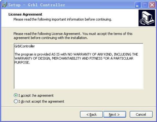
b. Install GrblController361 Software Grbl Controller software is used to send GCode to CNC Machines. Run Grbl Controller361 Setup in your installation packet, the interface below will come out:
Click Next to continue.
For a license agreement, please check I accept the agreement and click Next.
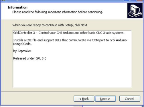
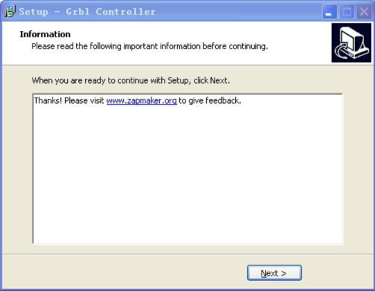
When you are ready to continue with Setup, click Next.
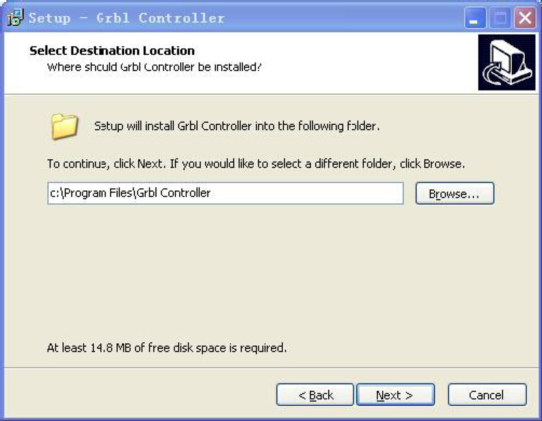
To continue, click Next. If you would like to select a different folder to install, click Browse.
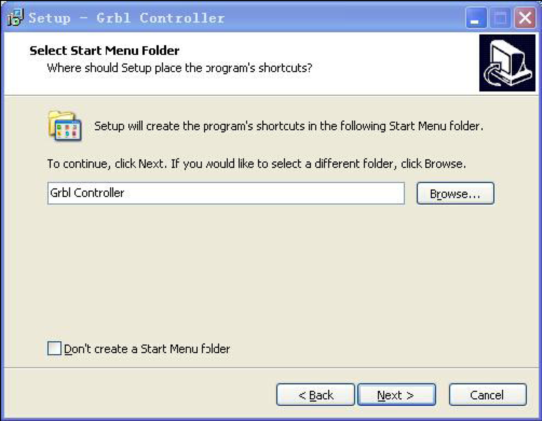
To continue, click Next. If you would like to select a different folder to place program’s shortcuts, click Browse.
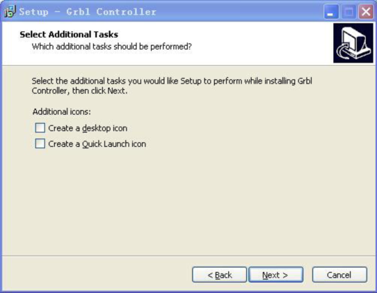
Select the additional tasks you would like Setup to perform while installing Grbl Controller, then click Next.
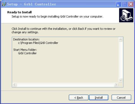
Click Install to continue with the installation.
Click Next.
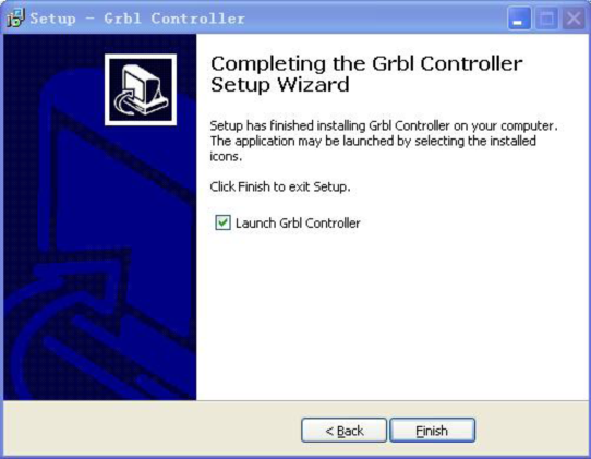
At last, click “Finish” to finish the installation.
c. Test G-Code on Grbl Controller
Power the main board using a USB cable and connect correctly all your external devices, then run Grbl Controller.
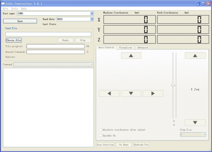
Choose Port name the same as IDE COM port and click “Open” to open the serial port, connecting CNC Machines with computer.
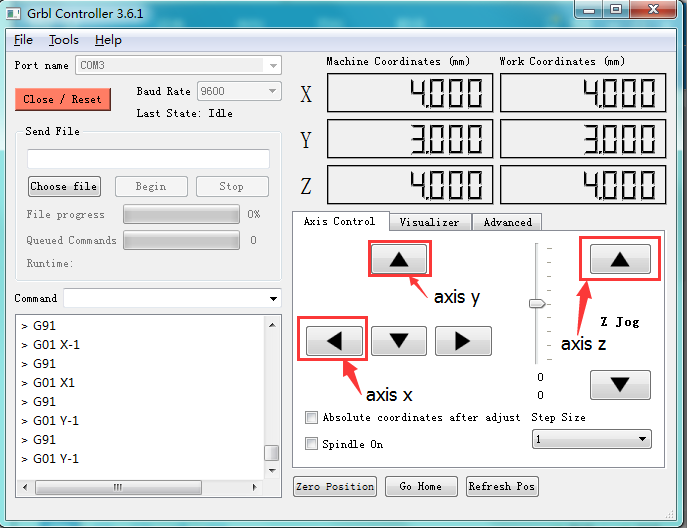
After opening the series port, the “Open” button change into “Close/Reset” and get red! At this time you can click the X axis、Y axis、Z axis as shown in below diagram to adjust the motion direction of motors.
Notes: after adjusting the axies, before beginning G-Code file, you must close and open again.
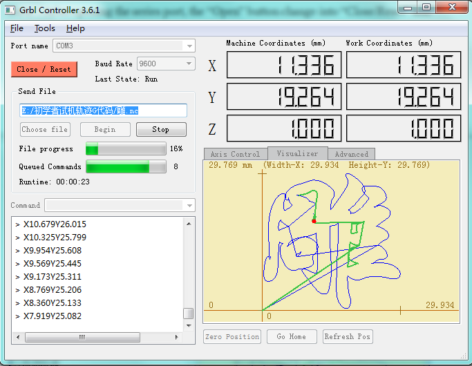
Now, it is time to have a try! Click ”Choose file” to choose one G-Code file named cn. to test in the data packet for a beginner, and the interface will come out:
Click “Begin” , and you can see how the motors move on coordinates.
Reference
All information download:
https://1drv.ms/u/s!ArhgRvK6-RyJhHZJBfgHK7DsVWYE?e=TWdriq
Arduino IDE Download:
https://www.arduino.cc/en/Main/OldSoftwareReleases#1.5.x
Download GRBL_Arduino_Library, Driver, G-Code and Grbl Controller361 setup:
