KS0320 Keyestudio Electromagnet Module (Black and Environmental-friendly)
Description
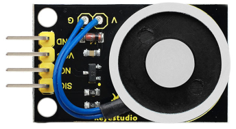
This module mainly contains an electromagnet. A magnet that generates a magnetic field from an electric current.
It uses the principle of electro-magnetic. With a straight metal wire passing through the current, the space around the wire will produce a circular magnetic field. In order to concentrate the magnetic field, the coil inside the electromagnet is wound into a coil, and many lines are arranged side by side, so that all the magnetic fields of the coil pass through the center of the coil, forming a strong magnetic field there, which can make it absorb a 1kg ferromagnetic.
When using this module, you can control the electromagnet on and off by controlling the High or Low level on its Signal end.
When using, we can connect the module to the arduino MCU. After using 5V power supply, connect the SIG pin of the module to the PWM port of the arduino board, set the PWM value, and adjust the magnetic field of the module. The larger the PWM value, the larger the magnetic field.
Features
- Small electromagnet induction, with high strength suction.
- Electromagnet built-in pure copper coil, strong conductivity, low power consumption.
- Electromagnet electric iron shell, less remanence, integrated molding, strong magnetic conductivity.
Parameters
- Working Voltage: DC 5V
- Working current: 0.3A (maximum)
- Maximum power: 3W
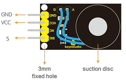
- Interface Type: 3PIN (pin pitch of 2.54mm)
PINOUTS
Connection Diagram
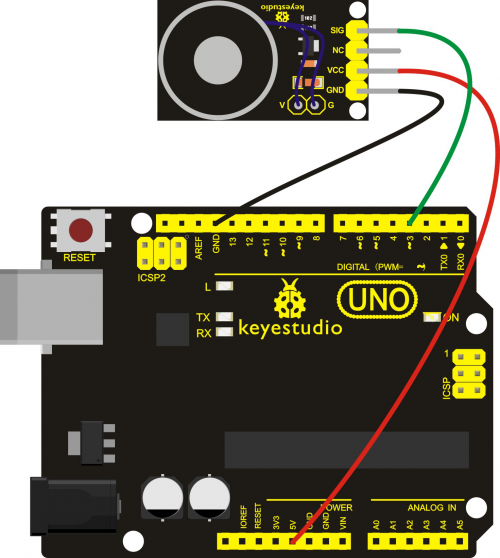
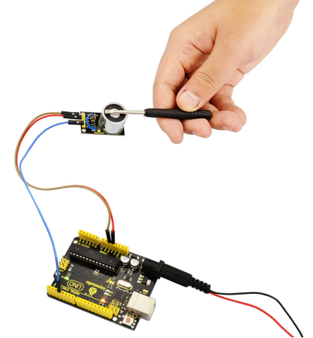
Connect up this module and UNO board like this: SIG pin to Digital port 3, VCC pin to 5V, GND pin to the ground port. Shown as below.
Example Code 1
Now, open up the Arduino IDE and type in the following code:
int Solenoid = 3;    //define digital port 3
 void setup()
 {
  pinMode(Solenoid, OUTPUT);  //set Solenoid as OUTPUT
}
 void loop()
{
  digitalWrite(Solenoid, HIGH);// Solenoid is effective
  delay(2000); // delay 2S
  digitalWrite(Solenoid, LOW);  // Solenoid is non-effective
  delay(2000);  //delay 2S
}
Example Code 2
int Solenoid = 3;    //define digital port3
 void setup()
 {
  pinMode(Solenoid, OUTPUT);  //set Solenoid as OUTPUT
}
 void loop()
{
  analogWrite(Solenoid, 250);
  delay(2000); //delay 2S
  analogWrite(Solenoid, 10);
  delay(2000); //delay 2S
  analogWrite(Solenoid, 150);
  delay(2000);  //delay 2S
  analogWrite(Solenoid, 50);
  delay(2000); //delay 2S
}
Example Result 1
After wiring, upload the above code to the board, if put an iron screwdriver close to the electromagnet module, they should be available to attract together for two seconds, then lose its magnetic attraction for two seconds, circularly.
Example Result 2
After uploading code 2, the magnetic field strength of the electromagnet on the module changes continuously and circulates alternately.
Resources
