KS0388 Keyestudio USB to ESP-01S Wifi Module Serial Port Shield
Introduction
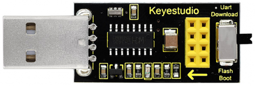
This is an expansion board for the ESP-01S WiFi module. The shield comes with a USB to Serial port chip CH340G.
Installed the driver, push the shield’s button to Flash Boot, and plug into computer’s USB port. You can use Serial debugging tool to test the AT command.
Push the shield’s button to Download, and plug into computer’s USB port, ESP-01 module is at download mode. You can download the firmware to ESP-01 module using firmware software.
Technical Parameters
- Working voltage: DC 5V
- Working current: minimum 500mA
- Communication voltage: 3.3V
- Environmental attributes: ROHS
- Dimensions: 55mm*18mm*12mm
- Weight: 5.6g
Driver Installation
The USB to serial port chip of this control board is CH340G. So you need to install the chip driver. You can click the driver file here usb_ch341_3.1.2009.06 to download.
https://drive.google.com/open?id=1E-KGJpTfksqAw174uTVVSDSPknfW6r0N
In different systems, the driver installation is similar. Here we start to install the driver on the Win7 system.
Plug one end of your USB cable into the Keyestudio ESP-01S WI-FI board and the other into a USB socket on your computer.
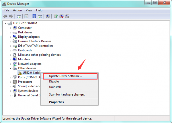
When you connect the WI-FI board to your computer at the first time, right click your “Computer” —>for “Properties”—> click the “Device manager”, under Other devices, you should see the “USB2.0-Serial”.
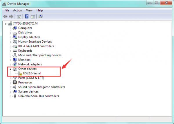
Then right-click on the “USB2.0-Serial” and select the top menu option (Update Driver Software...) shown as the figure below.
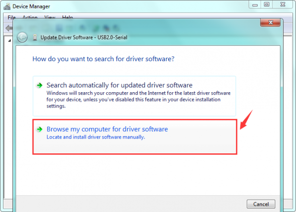
Then it will be prompted to either “Search Automatically for updated driver software” or “Browse my computer for driver software”. Shown as below.
In this page, select “Browse my computer for driver software”.
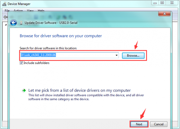
After that, select the option to browse and navigate to the “drivers” folder of usb-ch341 installation.
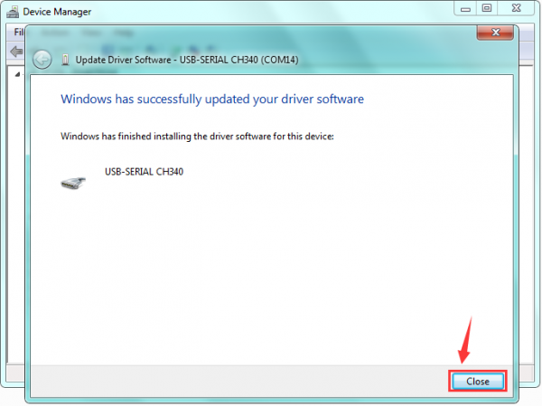
Once the software has been installed, you will get a confirmation message.
Installation completed, click “Close”.
Finally, the driver is installed well. You can right click “Computer” —>“Properties”—>“Device manager”, check out the CH340 device as the figure shown below.
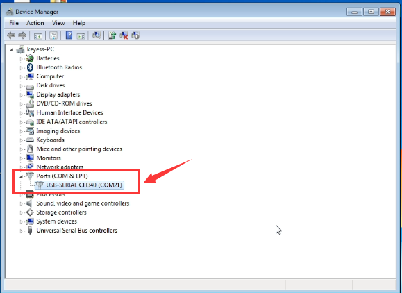
Here you can check out the Port COM21.
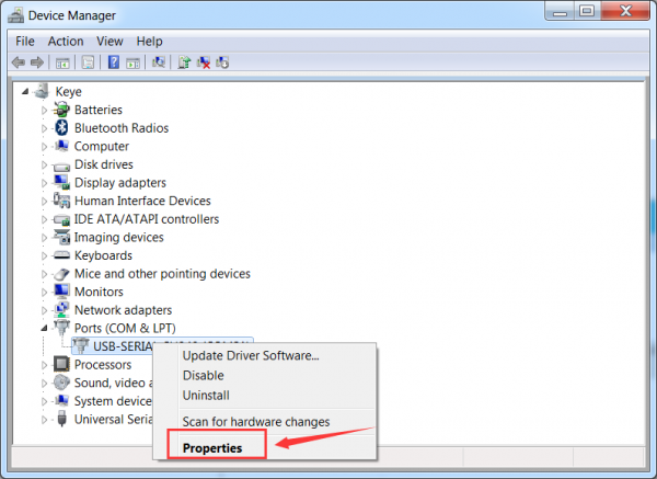
If you want to modify the COM Port. Follow the methods below.
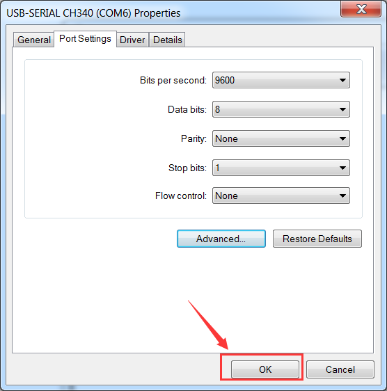
Right click the USB-SERIAL CH340 (COM21), then select Properties.
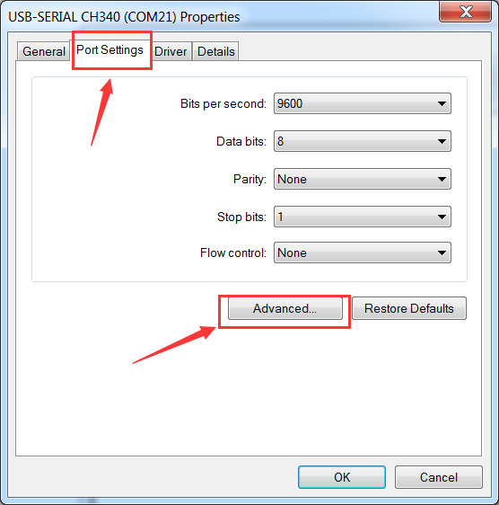
Pop up the following window, click Port Settings and Advanced.
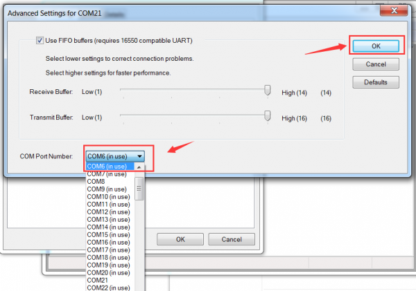
Then you can choose any COM ports as you like.
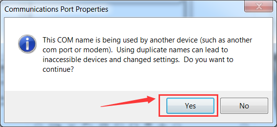
Here we select COM6, and click OK.
It will pop up the prompt window. Click Yes.
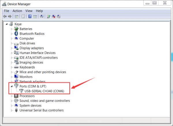
Now, set well the COM6. Shown below.
Use Method
1) AT Command Settings
When setting the AT command, you need to use an ESP8266 WIFI module.
Plug the ESP8266 WIFI onto the shield, and then connect them to your computer’s USB port using a mini USB cable. Then push the shield’s button to Flash Boot end.

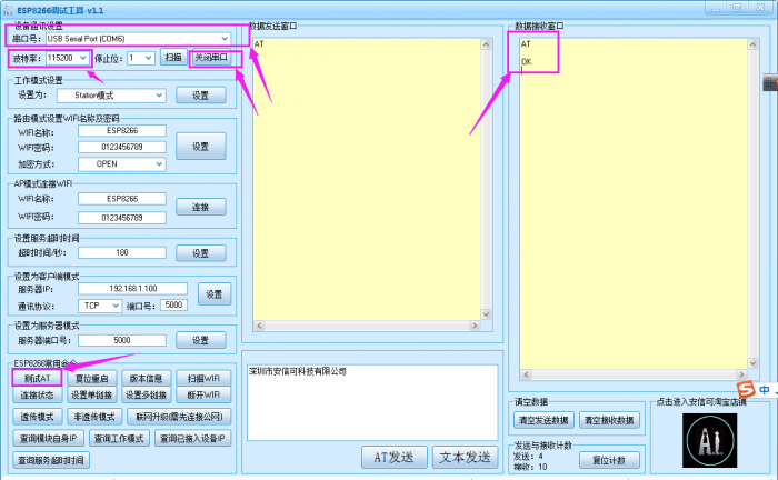
Connected successfully, open the ESP8266 debugging tool, set the baud rate to 115200, click to open the Serial Port, and click Test the AT.
You should see the data received window will print out AT OK.
To set other AT commands, the method is similar.
You can download the ESP8266 debugging tool from the link below:
https://drive.google.com/open?id=1TS56giNcC3Jd98Rg1mNyWyq13ePnZeyQ
2) Firmware Programming
When setting the AT command, you need to use an ESP8266 WIFI module.
Plug the ESP8266 WIFI onto the shield, and then connect them to your computer’s USB port using a mini USB cable. Then push the shield’s button to Download end.

Then open flash_download_tools_v3.6.5software, click to open.
![]()
You can download the flash download tools v3.6.5 from the link:
https://drive.google.com/open?id=1Zjg-lg7ySsmN4C3A0Oz9UJCdXqtkdf_R
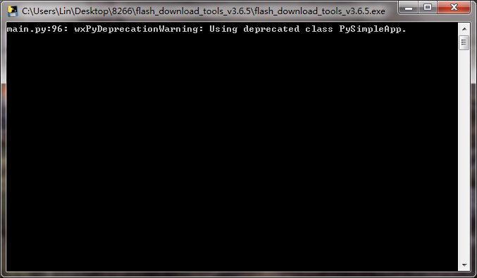
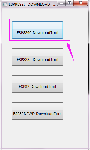
Wait for a minute, pop up the below interface, click the ESP8266 Download Tool.
Enter the interface to set the firmware burning. This is the address of firmware burning.
![]()
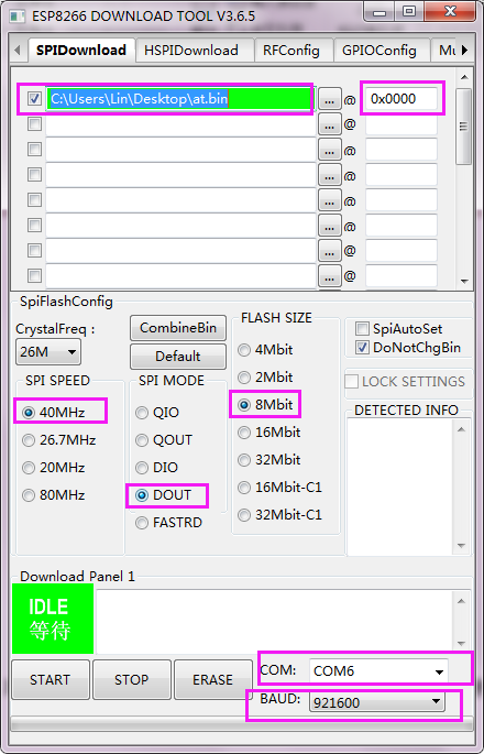
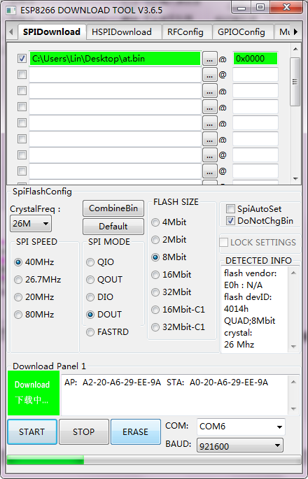
Hold the FLASH button on the shield, and Tap START button, then press RST button on the shield, release the FLASH button.
The module will enter the download mode. Shown below.
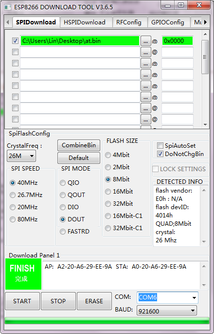
Firmware download completed, can enter the corresponding software to set the AT command.
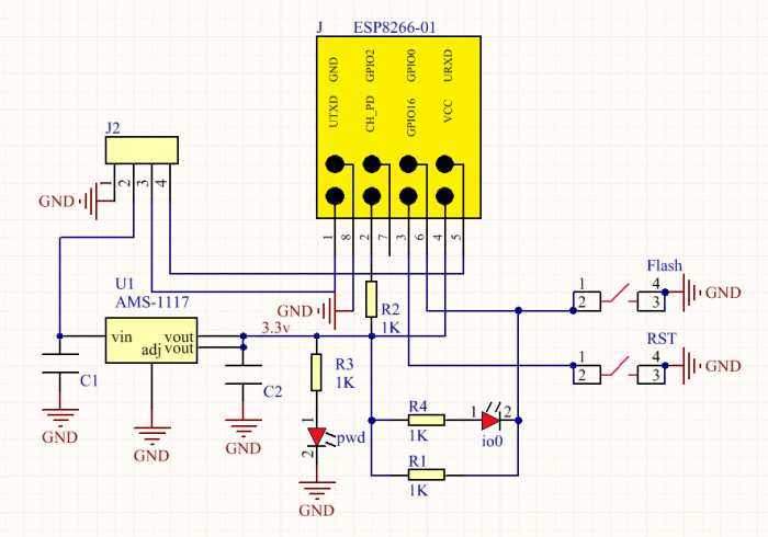
Schematic Diagram
Resources Download
- Download files:
https://fs.keyestudio.com/KS0388
Get One Now
