KS0521 Keyestudio Solar Charger Shield (Black and Eco-friendly)
Description
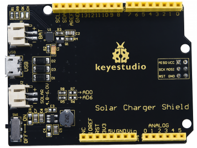
Keyestudio solar charger shield is home to energy collector, power management and charging, a stacked shield compatible with UNO R3 control board.
On this shield, BAT interface could output 5V when connected 3.0V-4.2V rechargeable batteries. At same time, the solar charger shield can be supplied power via the USB interface and SOL AR port. Yet, when the DIP is dialed to ON end, either external batteries or USB port supplies power to UNO R3 board.
Moreover, CH LED(red) will be on when charging the external batteries; and OK LED indicator will be on if they are fully charged.
Specification
- Output disconnect (dip switch control)
- Short circuit protection
- 5V output when battery is connected
- Continuous charging current up to 900mA
- Battery status indicator (red: charging, green: fully charged )
- Micro-USB connector
Parameters
- Battery input voltage: DC 3.0-4.5V
- USB input voltage: DC 4.75-5.25V
- Solar input voltage: DC 4.8-6V
- Maximum output power (with battery): 3W (600mA@5V)
- Ripple voltage: <100mV @ 500mA
- Size: 73*51mm
- Weight: 19.2g
Charging by the solar panel
- 1.The solar panel can charge the batteries by the sunlight and incandescent lamps. It can generate electricity from ultraviolet or infrared radiation.
- 2.When the solar panel is away from incandescent light less than 20 cm, the charging efficiency is low
- 3.Adjust the angle of solar panel to receive the light mostly
- 4.Excessive contact with water or water vapor may oxidize solar panels and reduce conversion efficiency.
- 5.Tear the plastic protection film covered on solar panel please before using it.
- 6. Take care of the solar panel and avoid scratches and collisions.
How to get started with solar panel
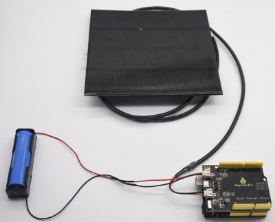
1.Connect the batteries and solar panel to the corresponding ports.
2.Place solar panel as follows
3.Ensure the red indicator turn on, as shown below:
4.Green indicator will be on if battery panel is fully charged.
5.After charging, install charger board on the V 4.0 control board, then it will supply power for V 4.0 board when dialing the dip switch to ON end.
Note: Solar board and battery are not included.
Test Method
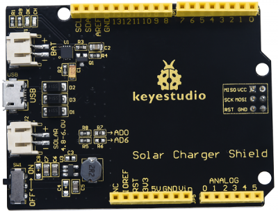
Connect the VBAT pin to A0 so that we can read the data from the A0 pin. Besides, we need to solder a 0Ω resistor at R7, as shown below.
Test Code
/*
 Solar charger shield voltage measurement example. Connect VBAT pin to analog pin A0.

 The pin measures 2.0 V when not under direct exposre to sunlight and 5V when exposed to sunlight.

 This example code is in the public domain.
 */
// These constants won't change.  They're used to give names
// to the pins used:
const int analogInPin = A0;  // Analog input pin that the VBAT pin is attached to

int BatteryValue = 0;        // value read from the VBAT pin
float outputValue = 0;        // variable for voltage calculation

void setup() {
    // initialize serial communications at 9600 bps:
    Serial.begin(9600);
}

void loop() {
    // read the analog in value:
    BatteryValue = analogRead(analogInPin);
    // Calculate the battery voltage value
    outputValue = (float(BatteryValue)*5)/1023*2;
    // print the results to the serial monitor:
    Serial.print("Analog value = " );
    Serial.print(BatteryValue);
    Serial.print("\t voltage = ");
    Serial.print(outputValue);
    Serial.println("V ");
    // wait 100 milliseconds before the next loop
    // for the analog-to-digital converter to settle
    // after the last reading:
    delay(100);
}
Test Result
An external 3.0-4.2V rechargeable battery is attached to the expansion board, and the DIP switch is dialed to the OFF end.
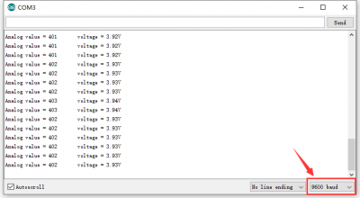
Upload the code, and stack the solar charger shield on the V 4.0 control board. After plugging in power by USB cable, open the serial monitor and set the baud rate to 9600.
The serial monitor displays the corresponding analog value and the voltage of rechargeable battery, as shown below.


