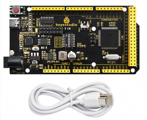
KS5014 Keyestudio 2560 WIFI PLUS Main Board
Introduction
Keyestudio 2560 WIFI PLUS Main Control Board adopts two MCU including ATmega 2560 and esp8266, containing all functions of Arduino Mega 2560and ESP8266 development board.
The two MCU combination is suitable for the development of the Internet of Things, networking functions, and independent wireless network construction.
The download function of the serial port is controlled by the toggle switch, and the codes of the two MCU can be burned separately by using a USB interface so that two development boards can be used alone or combined. It is very convenient when using.
Parameters
| Working Voltage | USB/5V; DC/7-16V advice DC9V(Esp8266/3.3V; ATmega 2560/5V) |
| Working Current | Maximum output 3.3V/800mA or 5V/1.6A |
| Maximum Power | 8W |
| Working Temperature Range | -10~50 °C |
| Dimensions | 103*53.5*13mm |
| Environmental Attributes | ROHS |
| ATmega 2560 Digital I/O | 54 pin (15 for PWM output; D20,D21 as regular I2C) |
| ATmega 2560 PWM Digital I/O | 15 pin |
| ATmega 2560 Analog Input Pin | 16 pin |
| DC of each ATmega 2560 I/O Pin | 20mA |
| ATmega 2560 flash | 256KB(8KB used for bootloader) |
| ATmega 2560 SRAM | 8KB |
| ATmega 2560 EEPROM | 4KB |
| ATmega 2560 Clock Speed | 16MHZ |
| Esp8266 Digital I/O | 9 on-board pin |
| Esp8266 PWM Digital I/O | 4 pin (IO4,IO12,IO14,IO15) |
| DC of each Esp8266 I/O Pin | 20mA |
| Esp8266 flash | 2MB |
| Esp8266 SRAM | 50kb |
| Esp8266 Clock Speed | 26MHZ |
| Esp8266 Radio Frequency | 2.4GHZ Receiver and Transmitter |
| Wifi | ESP8266EX supports TCP/IP protocol and 802.11 b/g/n WLAN MAC protocol. Supports Basic Service Set (BSS) STA and SoftAP operation under Distributed Control Function (DCF). Enables optimization of active hours by minimizing host interaction for power management. |
Interfaces and Components Description
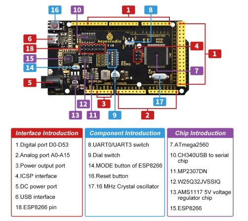
Special Function Interface
| Serial Communication | Port 0 D0(RX) and D1(TX) Port 1 D19(RX) and D18(TX) Port 2 D17(RX) and D16(TX) Port 3 D15(RX) and D14(TX) |
| External Interrupt | D2(Interrupt 0), D3(Interrupt1), D18(Interrupt5), D19(Interrupt4), D20(Interrupt3) and D21(Interrupt2) |
| PWM Interface | D2-D13 and D44-D46 |
| SPI Communication | D53(SS), D51(MOSI), D50(MISO), D52(SCK) |
| IIC Communication | D20(SDA), D21(SCL) |
| ICSP Interface | ATMEGA2560-16AU Interface for burning firmware |
| USB Interface | downloading programs and serial port debugging |
| DC Power Interface | able to connect to DC7V-16V,advice DC9V |
| Power Output Interface | 3.3V/5V output, often used for external power supply or common ground processing |
| Analog Interface | A0-A15 |
ESP8266 pin
(Logo of the board as the positive direction, pin attributes from left to right)
| VCC | RST | CH-PD | TX0 | GPIO5 | GPIO4 | GPIO12 |
| RX0 | GPIO0 | GPIO2 | GND | GPIO16 | TOUT | GND |
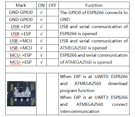
DIP Switch Description (ON/OFF)
Projects
Arduino 2560 Burn Test Program
Connect PLUS main control board to computer with USB cable.
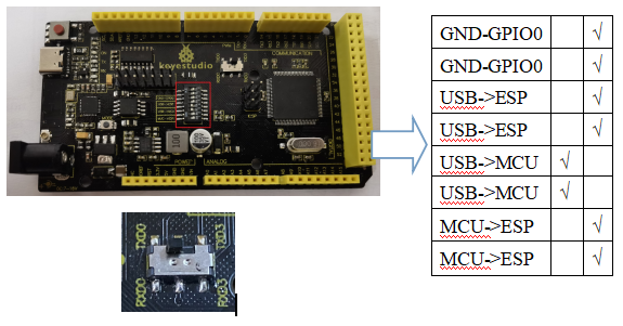
Taking Keyestudio LOGO as a reference, toggle the switch to the left for on and right for off.
The positions of the 16-pin DIP switch and the 6-pin DIP switch are shown below:
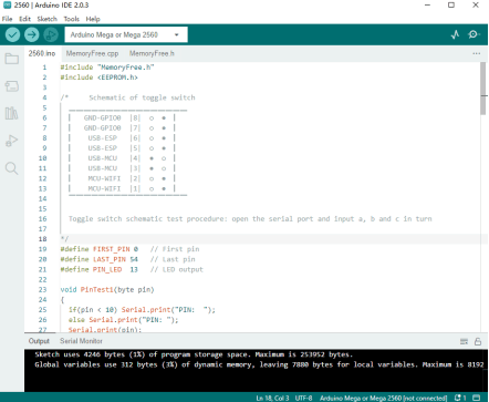
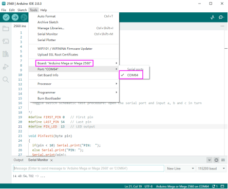
Choose the development board "Arduino Mega or Mega 2560" and port.
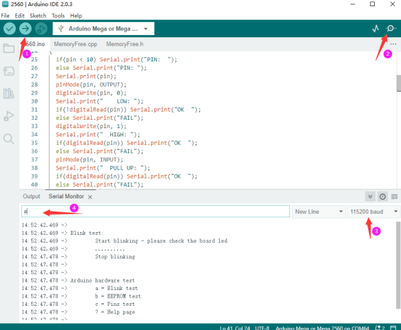
Click ![]() to upload the program to PLUS main control board, and wait for a prompt of successful uploading in the lower left corner.
to upload the program to PLUS main control board, and wait for a prompt of successful uploading in the lower left corner.
Then click ![]() to open the watch window and set baud rate at 115200; send sequentially:
to open the watch window and set baud rate at 115200; send sequentially:
a: lighting test (D13)
b: memory test
c: pin test
ESP8266 Burn Test Program
Connect PLUS main control board to computer with USB cable.
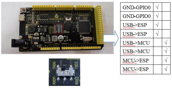
Taking Keyestudio LOGO as a reference, toggle the switch to the left for on and right for off.
The positions of the 16-pin DIP switch and the 6-pin DIP switch (toggle to serial port 1) are shown below:
Open ![]() under code\esp8266, and turn on the WIFI network sharing of the mobile phone or computer and set the name and password to be consistent with those in the program.
under code\esp8266, and turn on the WIFI network sharing of the mobile phone or computer and set the name and password to be consistent with those in the program.
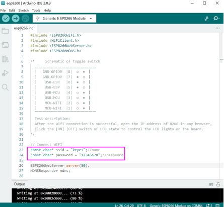
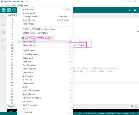
Choose the development board "Generic ESP8266 Module" and port.
Click ![]() to upload the program to PLUS main control board, and wait for a prompt of successful uploading in the lower left corner.
to upload the program to PLUS main control board, and wait for a prompt of successful uploading in the lower left corner.
If the upload fails, unplug the USB cable and reconnect it before uploading.
NOTE: Before each programming of esp8266, the switch must be toggled at GND-GPIO0, and it can be used as a normal IO port if turn it off after programming.
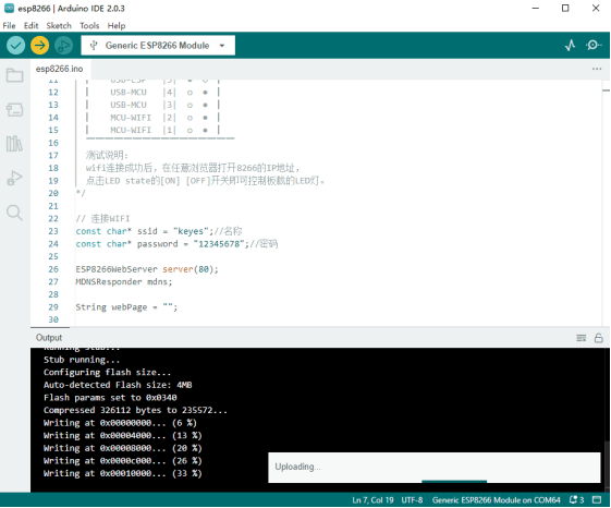
Test result:
The positions of 16-pin and 6-pin DIP switch are shown below:
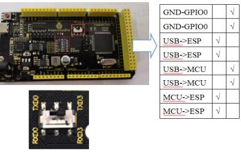
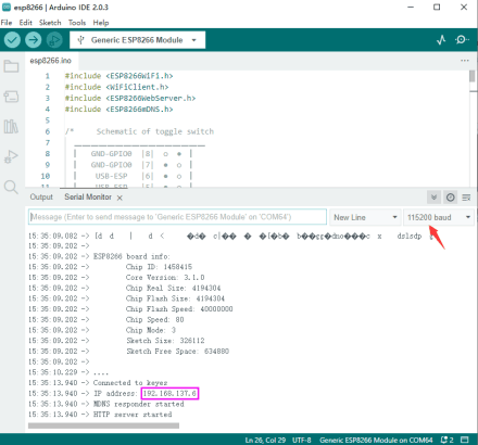
Click ![]() to open the watch window and set baud rate at 115200. After the ESP8266 of the main control board is connected to WIFI, the IP address is printed out on the monitoring serial port (Press RESERT button if not).
to open the watch window and set baud rate at 115200. After the ESP8266 of the main control board is connected to WIFI, the IP address is printed out on the monitoring serial port (Press RESERT button if not).
TEST_MEGA-ESP Remote Control
Upload the project on Chapter 7.2, and choose the development board when uploading.
Upload code "TEST_MEGA-ESP.ino" to the main control board and choose the development board "Arduino Mega or Mega 2560".
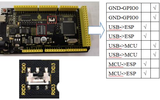
After successful uploading. Toggle the switch to the position shown below:
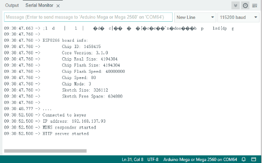
Open Hotpot and connect ESP8266 to WIFI network.
And open the serial port after successful connecting, IP address will be displayed.
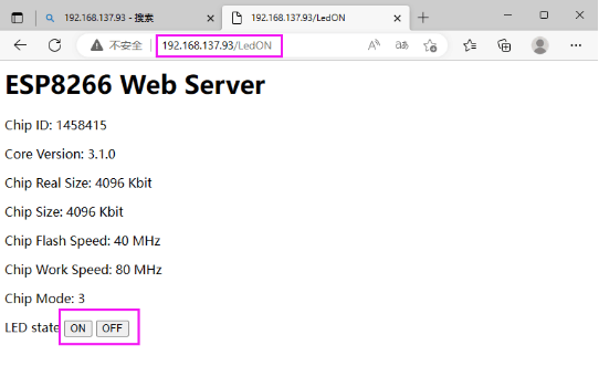
Open this address of 8266 on any browser, the [ON] [OFF] of LED state will control the onboard LED on 2560 and ESP8266.
Resources
For more details, please refer to:
https://fs.keyestudio.com/KS5014
