Ks0190 keyestudio Environment Monitoring Kit
keyestudio Environment Monitoring Kit
Kit Introduction
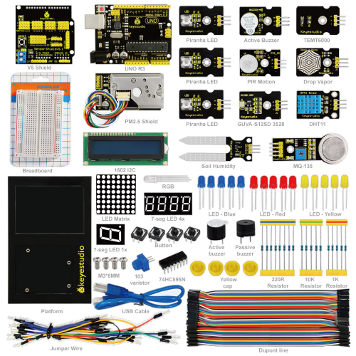
keyestudio Environment Monitoring Kit,the latest environmental study kit, greatly lowers the difficulty in program learning for enthusiasts. All computer language and professional grammars of a program can be simplified into blocks. Compiling is as easy as block building. Interactive with Arduino development board, they can achieve exciting works.
The open source feature of Arduino makes it extremely popular. You can find a many learning communities on the Internet. Ardublock is a programming environment, just like blocks building, which greatly lowers the learning difficulty for starters. As long as you love it, everyone can play with Arduino without professional knowledge or relevant background. As for parents who stress on the education of next generation, this will be one of your best way to interact with your children.
Project List
Project 1: Hello World!
Project 2: LED Blinking
Project 3: PWM Light Control
Project 4: Traffic Light
Project 5: LED Chasing Effect
Project 6: Button-controlled LED
Project 7: Responder
Project 8: Active Buzzer
Project 9: Passive Buzzer
Project 10: RGB LED
Project 11: Analog Value Reading
Project 12: 74HC595
Project 13: 1-digit LED Segment Display
Project 14: 4-digit LED Segment Display
Project 15: 8*8 LED Dot Matrix
Projects of Modules
Project 1 LED Blinking
Project 2 Active Buzzer Module
Project 3 Soil Module
Project 4 Steam Sensor
Project 5 MQ 135 Gas Sensor
Project 6 PIR Motion Sensor
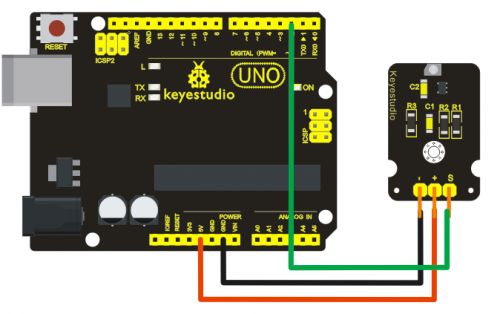
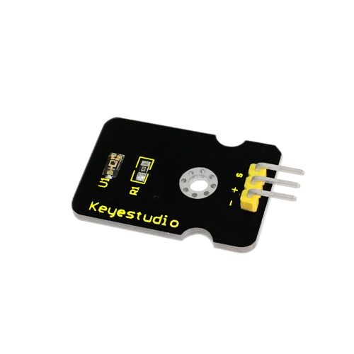
Project 7 GUVA-S12SD 3528 Ultraviolet Sensor
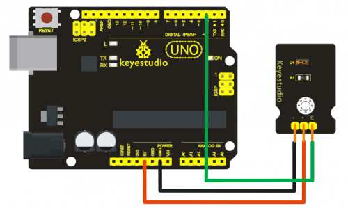
Project 8 TEMT6000 Ambient Light Sensor
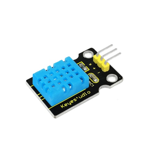
Project 9 DHT11 Temperature and Humidity Sensor
Project 10 GP2Y10 Dust Sensor
Project 11 I2C1602 Liquid Crystal Display Module
Project 12 Ambient Light Sensor to Control Brightness of LED
Project 13 Ultraviolet Sensor to Alarm
Project 14 Displaying Temperature and Humidity on LCD
Project Details
Project 1: Hello World
Introduction:
As for starters, we will begin with something simple. In this project, you only need an Arduino and a USB cable to start the "Hello World!" experiment. This is a communication test of your Arduino and PC, also a primer project for you to have your first try of the Arduino world!
Hardware Required:
- Arduino board x1
- USB cable x1
Sample Code:
After installing driver for Arduino, let's open Arduino software and compile code that enables Arduino to print "Hello World!" under your instruction. Of course, you can compile code for Arduino to continuously echo "Hello World!" without instruction. A simple If () statement will do the instruction trick. With the onboard LED connected to pin 13, we can instruct the LED to blink first when Arduino gets an instruction and then print "Hello World!”.
int val;//define variable val
int ledpin=13;// define digital interface 13
void setup()
{
  Serial.begin(9600);// set the baud rate at 9600 to match the software set up. When connected to a specific device, (e.g. bluetooth), the baud rate needs to be the same with it.
  pinMode(ledpin,OUTPUT);// initialize digital pin 13 as output. When using I/O ports on an Arduino, this kind of set up is always needed.
}
void loop()
{
  val=Serial.read();// read the instruction or character from PC to Arduino, and assign them to Val.
  if(val=='R')// determine if the instruction or character received is “R”.
  {  // if it’s “R”,
    digitalWrite(ledpin,HIGH);// set the LED on digital pin 13 on.
    delay(500);
    digitalWrite(ledpin,LOW);// set the LED on digital pin 13 off.    delay(500);
    Serial.println("Hello World!");// display“Hello World!”string.
  }
}
Result:
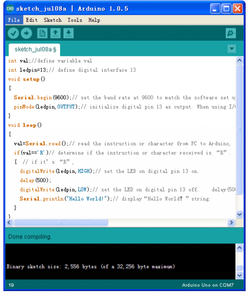
Done uploading the code, click to open serial monitor
Input R
LED 13 will blink once,
PC will receive information from Arduino: Hello World
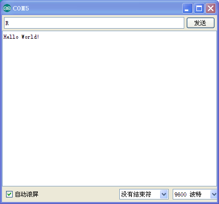
After choosing the right port, the experiment should be easy for you!
Project 2: LED Blinking
Introduction:
Blinking LED experiment is quite simple. In the "Hello World!" program, we have come across LED. This time, we are going to connect an LED to one of the digital pins rather than using LED13, which is soldered to the board. Except an Arduino and an USB cable, we will need extra parts as below:
Hardware Required:
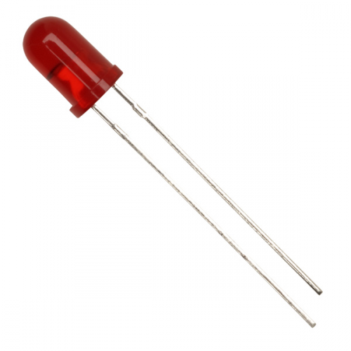
- 1. Red M5 LED*1
- 2. 220Ω resistor*1
- 3. Breadboard*1
- 4. Breadboard jumper wires* several
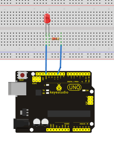
We follow below diagram from the experimental schematic link. Here we use digital pin 10. We connect LED to a 220 ohm resistor to avoid high current damaging the LED.
Sample Code:
int ledPin = 10; // define digital pin 10.
void setup()
{
pinMode(ledPin, OUTPUT);// define pin with LED connected as output.
}
void loop()
{
digitalWrite(ledPin, HIGH); // set the LED on.
delay(1000); // wait for a second.
digitalWrite(ledPin, LOW); // set the LED off.
delay(1000); // wait for a second
}
Result:
After downloading this program, in the experiment, you will see the LED connected to pin 10 turning on and off, with an interval approximately one second.
The blinking LED experiment is now completed. Thank you!
Project 3: PWM Light Control
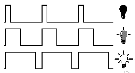
PWM, short for Pulse Width Modulation, is a technique used to encode analog signal level into digital ones. A computer cannot output analog voltage but only digital voltage values such as 0V or 5V. So we use a high resolution counter to encode a specific analog signal level by modulating the duty cycle of PMW. The PWM signal is also digitalized because in any given moment, fully on DC power supply is either 5V (ON), or 0V (OFF). The voltage or current is fed to the analog load (the device that uses the power) by repeated pulse sequence being ON or OFF. Being on, the current is fed to the load; being off, it's not. With adequate bandwidth, any analog value can be encoded using PWM. The output voltage value is calculated via the on and off time. Output voltage = (turn on time/pulse time) * maximum voltage value
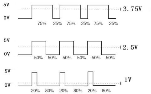
PWM has many applications: lamp brightness regulating, motor speed regulating, sound making, etc.
The following are the three basic parameters of PMW:
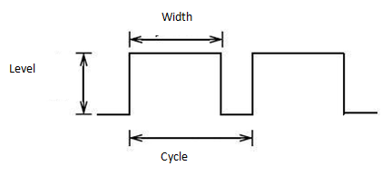
1. The amplitude of pulse width (minimum / maximum)
2. The pulse period (The reciprocal of pulse frequency in 1 second)
3. The voltage level(such as:0V-5V)
There are 6 PMW interfaces on Arduino, namely digital pin 3, 5, 6, 9, 10, and 11. In previous experiments, we have done "button-controlled LED", using digital signal to control digital pin, also one about potentiometer. This time, we will use a potentiometer to control the brightness of the LED.
Hardware Required:
1. Potentiometer*1
2. Red M5 LED*1
3. 220Ω resistor
4. Breadboard*1
5. Breadboard jumper wires*several
The input of potentiometer is analog, so we connect it to analog port, and LED to PWM port. Different PWM signal can regulate the brightness of the LED.
Connection for UNO R3:
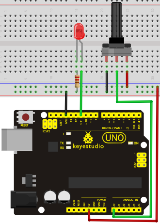
Sample Code:
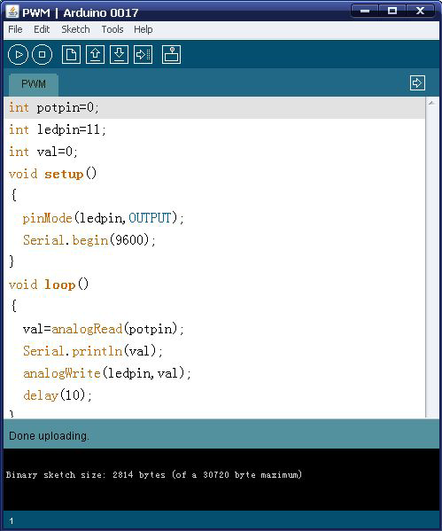
In the program compiling process, we will use the analogWrite (PWM interface, analog value) function. In this experiment, we will read the analog value of the potentiometer and assign the value to PWM port, so there will be corresponding change to the brightness of the LED. One final part will be displaying the analog value on the screen. You can consider this as the "analog value reading" project adding the PWM analog value assigning part. Below is a sample program for your reference.
int potpin=0;// initialize analog pin 0
int ledpin=11;//initialize digital pin 11(PWM output)
int val=0;// Temporarily store variables' value from the sensor
void setup()
{
pinMode(ledpin,OUTPUT);// define digital pin 11 as “output”
Serial.begin(9600);// set baud rate at 9600
// attention: for analog ports, they are automatically set up as “input”
}
void loop()
{
val=analogRead(potpin);// read the analog value from the sensor and assign it to val
Serial.println(val);// display value of val
analogWrite(ledpin,val/4);// turn on LED and set up brightness(maximum output of PWM is 255)
delay(10);// wait for 0.01 second
}
Result:
After downloading the program, when we rotate the potentiometer knob, we can see changes of the displaying value, also obvious change of the LED brightness on the breadboard.
Project 4: Traffic Light
Introduction:
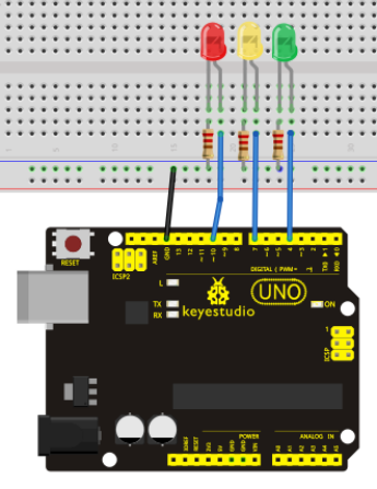
In the previous program, we have done the LED blinking experiment with one LED. Now, it’s time to up the stakes and do a bit more complicated experiment-traffic lights. Actually, these two experiments are similar. While in this traffic lights experiment, we use 3 LEDs with different color other than 1 LED.
Hardware Required:
1. Arduino board *1
2. USB cable *1
3. Red M5 LED*1
4. Yellow M5 LED*1
5. Green M5 LED*1
6. 220Ω resistor *3
7. Breadboard*1
8. Breadboard jumper wires* several
Sample Code:
Since it is a simulation of traffic lights, the blinking time of each LED should be the same with those in traffic lights system. In this program, we use Arduino delay () function to control delay time, which is much simpler than C language.
int redled =10; // initialize digital pin 8.
int yellowled =7; // initialize digital pin 7.
int greenled =4; // initialize digital pin 4.
void setup()
{
pinMode(redled, OUTPUT);// set the pin with red LED as “output”
pinMode(yellowled, OUTPUT); // set the pin with yellow LED as “output”
pinMode(greenled, OUTPUT); // set the pin with green LED as “output”
}
void loop()
{
digitalWrite(greenled, HIGH);//// turn on green LED
delay(5000);// wait 5 seconds
digitalWrite(greenled, LOW); // turn off green LED
for(int i=0;i<3;i++)// blinks for 3 times
{
delay(500);// wait 0.5 second
digitalWrite(yellowled, HIGH);// turn on yellow LED
delay(500);// wait 0.5 second
digitalWrite(yellowled, LOW);// turn off yellow LED
}
delay(500);// wait 0.5 second
digitalWrite(redled, HIGH);// turn on red LED
delay(5000);// wait 5 second
digitalWrite(redled, LOW);// turn off red LED
}
Result:
When the uploading process is completed, we can see traffic lights of our own design.
Note: this circuit design is very similar with the one in LED chase effect.
The green light will be on for 5 seconds, and then off., followed by the yellow light blinking for 3 times, and then the red light on for 5 seconds, forming a cycle. Cycle then repeats.
Experiment is now completed, thank you.
Project 5: LED Chasing Effect
Introduction:
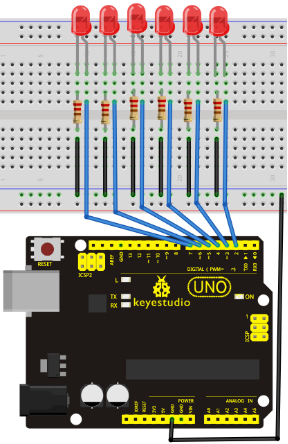
We often see billboards composed of colorful LEDs. They are constantly changing to form various effects. In this experiment, we compile a program to simulate chase effect.
Hardware Required:
1. Led x6
2. 220Ω resistor x6
3. Colorful breadboard wires
Sample Code:
int BASE = 2 ;  // the I/O pin for the first LED
int NUM = 6;   // number of LEDs

void setup()
{
   for (int i = BASE; i < BASE + NUM; i ++)
   {
     pinMode(i, OUTPUT);   // set I/O pins as output
   }
}

void loop()
{
   for (int i = BASE; i < BASE + NUM; i ++)
   {
     digitalWrite(i, LOW);    // set I/O pins as “low”, turn off LEDs one by one.
     delay(200);        // delay
   }
   for (int i = BASE; i < BASE + NUM; i ++)
   {
     digitalWrite(i, HIGH);    // set I/O pins as “high”, turn on LEDs one by one
     delay(200);        // delay
   }
}
Result:
You can see the LEDs blink by sequence.
Project 6: Button-controlled LED
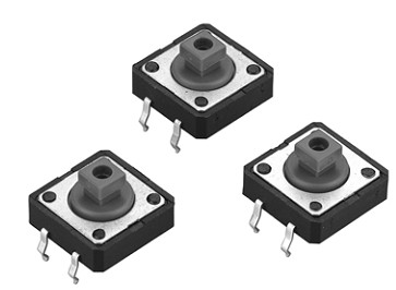
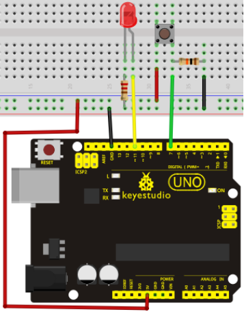
I/O port means interface for INPUT and OUTPUT. Up until now, we have only used its OUTPUT function. In this experiment, we will try to use the input function, which is to read the output value of device connecting to it. We use 1 button and 1 LED using both input and output to give you a better understanding of the I/O function. Button switches, familiar to most of us, are a switch value (digital value) component. When it's pressed, the circuit is in closed (conducting) state.
Hardware Required:
1. Button switch*1
2. Red M5 LED*1
3. 220Ω resistor*1
4. 10KΩ resistor*1
5. Breadboard*1
6. Breadboard jumper wires*several
Sample Code:
Now, let's begin the compiling. When the button is pressed, the LED will be on. After the previous study, the coding should be easy for you. In this program, we add a statement of judgment. Here, we use an if () statement.
Arduino IDE is based on C language, so statements of C language such as while, switch etc. can certainly be used for Arduino program.
When we press the button, pin 7 will output high level. We can program pin 11 to output high level and turn on the LED. When pin 7 outputs low level, pin 11 also outputs low level and the LED remains off.
int ledpin=11;// initialize pin 11
int inpin=7;// initialize pin 7
int val;// define val
void setup()
{
pinMode(ledpin,OUTPUT);// set LED pin as “output”
pinMode(inpin,INPUT);// set button pin as “input”
}
void loop()
{
val=digitalRead(inpin);// read the level value of pin 7 and assign if to val
if(val==LOW)// check if the button is pressed, if yes, turn on the LED
{ digitalWrite(ledpin,LOW);}
else
{ digitalWrite(ledpin,HIGH);}
}
Result:
When the button is pressed, LED is on, otherwise, LED remains off. After the above process, the button controlled LED experiment is completed. The simple principle of this experiment is widely used in a variety of circuit and electric appliances. You can easily come across it in your every day life. One typical example is when you press a certain key of your phone, the backlight will be on.
Project 7: Responder
Introduction:
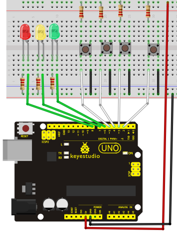
After completing all the previous experiments, we believe you will find this one easy. In this program, we have 3 buttons and a reset button controlling the corresponding 3 LEDs, using 7 digital I/O pins.
Sample Code:
int redled=8;     // set red LED as “output”
int yellowled=7;  // set yellow LED as “output”
int greenled=6;   // set green LED as “output”
int redpin=5;     // initialize pin for red button
int yellowpin=4;  // initialize pin for yellow button
int greenpin=3;   // initialize pin for green button
int restpin=2;   // initialize pin for reset button
int red;
int yellow;
int green;
void setup()
{
pinMode(redled,OUTPUT);
pinMode(yellowled,OUTPUT);
pinMode(greenled,OUTPUT);
pinMode(redpin,INPUT);
pinMode(yellowpin,INPUT);
pinMode(greenpin,INPUT);
}
void loop()  // repeatedly read pins for buttons
{
red=digitalRead(redpin);
yellow=digitalRead(yellowpin);
green=digitalRead(greenpin);
if(red==LOW)RED_YES();
if(yellow==LOW)YELLOW_YES();
if(green==LOW)GREEN_YES();
}

void RED_YES()// execute the code until red light is on; end cycle when reset button is pressed
{
  while(digitalRead(restpin)==1)
  {
   digitalWrite(redled,HIGH);
   digitalWrite(greenled,LOW);
   digitalWrite(yellowled,LOW);
  }
  clear_led();
}
void YELLOW_YES()// execute the code until yellow light is on; end cycle when reset button is pressed
{
  while(digitalRead(restpin)==1)
  {
  digitalWrite(redled,LOW);
  digitalWrite(greenled,LOW);
  digitalWrite(yellowled,HIGH);
  }
  clear_led();
}
void GREEN_YES()// execute the code until green light is on; end cycle when reset button is pressed
{
  while(digitalRead(restpin)==1)
  {
  digitalWrite(redled,LOW);
  digitalWrite(greenled,HIGH);
  digitalWrite(yellowled,LOW);
  }
  clear_led();
}
void clear_led()// all LED off
{
  digitalWrite(redled,LOW);
  digitalWrite(greenled,LOW);
  digitalWrite(yellowled,LOW);
}
Project 8: Active Buzzer
Introduction:
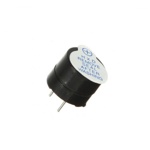
Active buzzer is widely used on computer, printer, alarm, electronic toy, telephone, timer etc as a sound making element. It has an inner vibration source. Simply connect it with 5V power supply, it can buzz continuously.
Hardware Required:
1. Buzzer*1
2. Key *1
3. Breadboard*1
4. Breadboard jumper wires*several
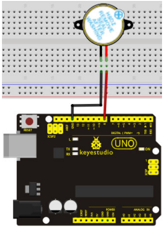
When connecting the circuit, pay attention to the positive & the negative poles of the buzzer. In the photo, you can see there are red and black lines. When the circuit is finished, you can begin programming.
Sample Code:
Program is simple. You control the buzzer by outputting high/low level.
int buzzer=8;// initialize digital IO pin that controls the buzzer
void setup()
{
  pinMode(buzzer,OUTPUT);// set pin mode as “output”
}
void loop()
{
digitalWrite(buzzer, HIGH); // produce sound
}
Result:
After downloading the program, the buzzer experiment is completed. You can see the buzzer is ringing.
Project 9: Passive Buzzer
Introduction:
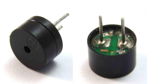
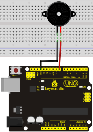
We can use Arduino to make many interactive works of which the most commonly used is acoustic-optic display. All the previous experiment has something to do with LED. However, the circuit in this experiment can produce sound. Normally, the experiment is done with a buzzer or a speaker while buzzer is simpler and easier to use. The buzzer we introduced here is a passive buzzer. It cannot be actuated by itself, but by external pulse frequencies. Different frequencies produce different sounds. We can use Arduino to code the melody of a song, which is actually quite fun and simple.
Hardware Required:
1.Passive buzzer*1
2. Key *1
3. Breadboard*1
4. Breadboard jumper wires* several
Sample Code:
int buzzer=8;// select digital IO pin for the buzzer
void setup()
{
pinMode(buzzer,OUTPUT);// set digital IO pin pattern, OUTPUT to be output
}
void loop()
{ unsigned char i,j;//define variable
while(1)
{ for(i=0;i<80;i++)// output a frequency sound
{ digitalWrite(buzzer,HIGH);// sound
delay(1);//delay1ms
digitalWrite(buzzer,LOW);//not sound
delay(1);//ms delay
}
for(i=0;i<100;i++)// output a frequency sound
{ digitalWrite(buzzer,HIGH);// sound
digitalWrite(buzzer,LOW);//not sound
delay(2);//2ms delay
}
}
}
Result:
After downloading the program, the buzzer experiment is completed.
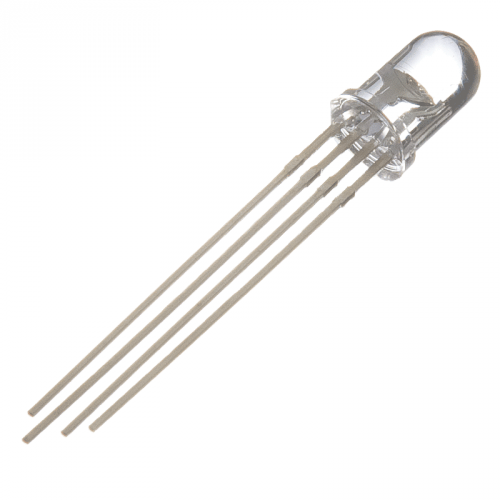
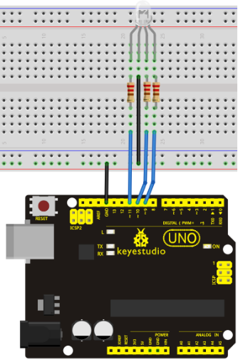
Project 10: RGB LED
Tricolor principle to display various colors
PWM controlling ports to display full color
Can be driven directly by Arduino PWM interfaces
Hardware Required:
Arduino Controller * 1
USB Cable * 1
RGB LED * 1
Sample Code:
int redpin = 11; //select the pin for the red LED
int bluepin =10; // select the pin for the blue LED
int greenpin =9;// select the pin for the green LED

int val;

void setup() {
  pinMode(redpin, OUTPUT);
  pinMode(bluepin, OUTPUT);
  pinMode(greenpin, OUTPUT);
  Serial.begin(9600);
}

void loop()
{
for(val=255; val>0; val--)
  {
   analogWrite(11, val);
   analogWrite(10, 255-val);
   analogWrite(9, 128-val);
   delay(1);
  }
for(val=0; val<255; val++)
  {
   analogWrite(11, val);
   analogWrite(10, 255-val);
   analogWrite(9, 128-val);
   delay(1);
  }
 Serial.println(val, DEC);
}
Result:
Directly copy the above code into arduino IDE, and click upload ![]() , wait a few seconds, you can see a full-color LED
, wait a few seconds, you can see a full-color LED
Project 11: Analog Value Reading
Introduction:
In this experiment, we will begin the learning of analog I/O interfaces. On an Arduino, there are 6 analog interfaces numbered from 0 to 5. These 6 interfaces can also be used as digital ones numbered as 14-19. After a brief introduction, let's begin our project. Potentiometer used here is a typical output component of analog value that is familiar to us.
Hardware Required:
1.Potentiometer *1
2.Breadboard*1
3.Breadboard jumper wires * several
Connection:
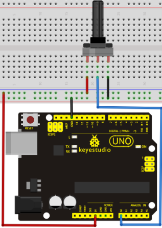
In this experiment, we will convert the resistance value of the potentiometer to analog ones and display it on the screen. This is an application we need to master well for our future experiments.
Connection circuit as below:
We use the analog interface 0.
The analog interface we use here is interface 0.
Sample Code:
The program compiling is simple. An analogRead () Statement can read the value of the interface. The A/D acquisition of Arduino 328 is in 10 bits, so the value it reads is among 0 to 1023. One difficulty in this project is to display the value on the screen, which is actually easy to learn. First, we need to set the baud rate in voidsetup (). Displaying the value is a communication between Arduino and PC, so the baud rate of the Arduino should match the the one in the PC's software set up. Otherwise, the display will be messy codes or no display at all. In the lower right corner of the Arduino software monitor window, there is a button for baud rate set up. The set up here needs to match the one in the program. The statement in the program is Serial.begin(); enclosed is the baud rate value, followed by statement for displaying. You can either use Serial.print() or Serial.println() statement.
int potpin=0;// initialize analog pin 0
int ledpin=13;// initialize digital pin 13
int val=0;// define val, assign initial value 0
void setup()
{
pinMode(ledpin,OUTPUT);// set digital pin as “output”
Serial.begin(9600);// set baud rate at 9600
}
void loop()
{
digitalWrite(ledpin,HIGH);// turn on the LED on pin 13
delay(50);// wait for 0.05 second
digitalWrite(ledpin,LOW);// turn off the LED on pin 13
delay(50);// wait for 0.05 second
val=analogRead(potpin);// read the analog value of analog pin 0, and assign it to val
Serial.println(val);// display val’s value
}
Result:
The sample program uses the built-in LED connected to pin 13. Each time the device reads a value, the LED blinks.
Below is the analog value it reads.
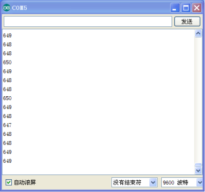
When you rotate the potentiometer knob, you can see the displayed value changes. The reading of analog value is a very common function since most sensors output analog value. After calculation, we can have the corresponding value we need.
The experiment is now completed, thank you.
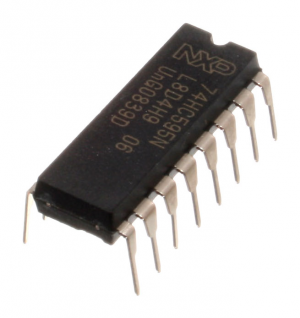
Project 12: 74HC595
To put it simply, 74HC595 is a combination of 8-digit shifting register, memorizer and equipped with tri-state output. Here, we use it to control 8 LEDs. You may wonder why use a 74HC595 to control LED? Well, think about how many I/O it takes for an Arduino to control 8 LEDs? Yes, 8. For an Arduino 168, it has only 20 I/O including analog ports. So, to save port resources, we use 74HC595 to reduce the number of ports it needs. Using 74HC595 enables us to use 3 digital I/O port to control 8 LEDs!
Hardware Required:
1.74HC595 chip*1
2.Red M5 LED*4
3.Green M5 LED*4
4.220Ω resistor*8
5.Breadboard*1
6.Breadboard jumper wires*several
Note: for pin 13 OE port of 74HC595, it needs to connect to GND
Connection for UNO R3:
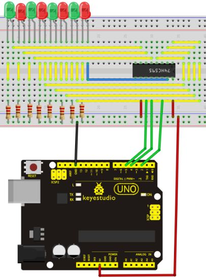
The circuit may seem complicated, but once you give it a good look, you will find it easy!
Sample Code:
int data = 2;// set pin 14 of 74HC595as data input pin SI
int clock = 5;// set pin 11 of 74hc595 as clock pin SCK
int latch = 4;// set pin 12 of 74hc595 as output latch RCK
int ledState = 0;
const int ON = HIGH;
const int OFF = LOW;
void setup()
{
pinMode(data, OUTPUT);
pinMode(clock, OUTPUT);
pinMode(latch, OUTPUT);
}
void loop()
{
for(int i = 0; i < 256; i++)
{
updateLEDs(i);
delay(500);
}
}
void updateLEDs(int value)
{
digitalWrite(latch, LOW);//
shiftOut(data, clock, MSBFIRST, ~value);// serial data “output”, high level first
digitalWrite(latch, HIGH);// latch
}
Result:
After downloading the program, you can see 8 LEDs displaying 8-bit binary number.
Project 13: 1-digit LED Segment Display
Introduction:
LED segment displays are common for displaying numerical information. It's widely applied on displays of electromagnetic oven, full automatic washing machine, water temperature display, electronic clock etc. It is necessary that we learn how it works.
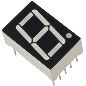
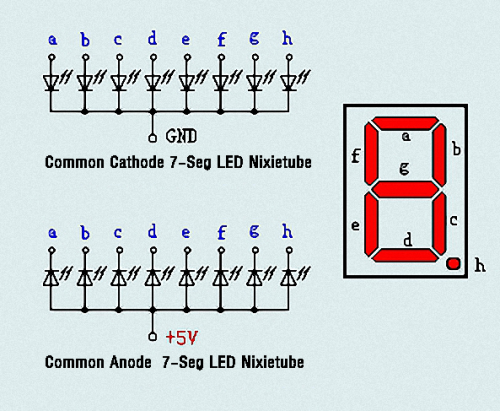
LED segment display is a semiconductor light-emitting device. Its basic unit is a light-emitting diode (LED). LED segment display can be divided into 7-segment display and 8-segment display according to the number of segments. 8-segment display has one more LED unit ( for decimal point display) than 7-segment one. In this experiment, we use a 8-segment display. According to the wiring method of LED units, LED segment displays can be divided into display with common anode and display with common cathode. Common anode display refers to the one that combine all the anodes of LED units into one common anode (COM).
For the common anode display, connect the common anode (COM) to +5V. When the cathode level of a certain segment is low, the segment is on; when the cathode level of a certain segment is high, the segment is off. For the common cathode display, connect the common cathode (COM) to GND. When the anode level of a certain segment is high, the segment is on; when the anode level of a certain segment is low, the segment is off.
Each segment of the display consists of an LED. So when you use it, you also need use a current-limiting resistor. Otherwise, LED will be burnt out. In this experiment, we use a common cathode display. As we mentioned above, for common cathode display, connect the common cathode (COM) to GND. When the anode level of a certain segment is high, the segment is on; when the anode level of a certain segment is low, the segment is off.
Hardware Required:
1.8-DIGIT segment display*1
2.220Ω resistor*8
3.Breadboard*1
4.Breadboard jumper wires*several
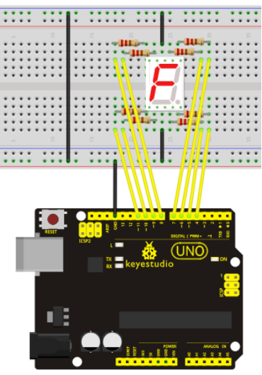
Connection :
Refer to below connection diagram for circuit connection
Sample Code:
There are seven segments for numerical display, one for decimal point display. Corresponding segments will be turned on when displaying certain numbers. For example, when displaying number 1, b and c segments will be turned on. We compile a subprogram for each number, and compile the main program to display one number every 2 seconds, cycling display number 0 ~ 9. The displaying time for each number is subject to the delay time, the longer the delay time, the longer the displaying time.
// set the IO pin for each segment
int a=7;// set digital pin 7 for segment a
int b=6;// set digital pin 6 for segment b
int c=5;// set digital pin 5 for segment c
int d=10;// set digital pin 10 for segment d
int e=11;// set digital pin 11 for segment e
int f=8;// set digital pin 8 for segment f
int g=9;// set digital pin 9 for segment g
int dp=4;// set digital pin 4 for segment dp
void digital_0(void) // display number 5
{
unsigned char j;
digitalWrite(a,HIGH);
digitalWrite(b,HIGH);
digitalWrite(c,HIGH);
digitalWrite(d,HIGH);
digitalWrite(e,HIGH);
digitalWrite(f,HIGH);
digitalWrite(g,LOW);
digitalWrite(dp,LOW);
}
void digital_1(void) // display number 1
{
unsigned char j;
digitalWrite(c,HIGH);// set level as “high” for pin 5, turn on segment c
digitalWrite(b,HIGH);// turn on segment b
for(j=7;j<=11;j++)// turn off other segments
digitalWrite(j,LOW);
digitalWrite(dp,LOW);// turn off segment dp
}
void digital_2(void) // display number 2
{
unsigned char j;
digitalWrite(b,HIGH);
digitalWrite(a,HIGH);
for(j=9;j<=11;j++)
digitalWrite(j,HIGH);
digitalWrite(dp,LOW);
digitalWrite(c,LOW);
digitalWrite(f,LOW);
}
void digital_3(void) // display number 3
{digitalWrite(g,HIGH);
digitalWrite(a,HIGH);
digitalWrite(b,HIGH);
digitalWrite(c,HIGH);
digitalWrite(d,HIGH);
digitalWrite(dp,LOW);
digitalWrite(f,LOW);
digitalWrite(e,LOW);
}
void digital_4(void) // display number 4
{digitalWrite(c,HIGH);
digitalWrite(b,HIGH);
digitalWrite(f,HIGH);
digitalWrite(g,HIGH);
digitalWrite(dp,LOW);
digitalWrite(a,LOW);
digitalWrite(e,LOW);
digitalWrite(d,LOW);
}
void digital_5(void) // display number 5
{
unsigned char j;
digitalWrite(a,HIGH);
digitalWrite(b, LOW);
digitalWrite(c,HIGH);
digitalWrite(d,HIGH);
digitalWrite(e, LOW);
digitalWrite(f,HIGH);
digitalWrite(g,HIGH);
digitalWrite(dp,LOW);
}
void digital_6(void) // display number 6
{
unsigned char j;
for(j=7;j<=11;j++)
digitalWrite(j,HIGH);
digitalWrite(c,HIGH);
digitalWrite(dp,LOW);
digitalWrite(b,LOW);
}
void digital_7(void) // display number 7
{
unsigned char j;
for(j=5;j<=7;j++)
digitalWrite(j,HIGH);
digitalWrite(dp,LOW);
for(j=8;j<=11;j++)
digitalWrite(j,LOW);
}
void digital_8(void) // display number 8
{
unsigned char j;
for(j=5;j<=11;j++)
digitalWrite(j,HIGH);
digitalWrite(dp,LOW);
}
void digital_9(void) // display number 5
{
unsigned char j;
digitalWrite(a,HIGH);
digitalWrite(b,HIGH);
digitalWrite(c,HIGH);
digitalWrite(d,HIGH);
digitalWrite(e, LOW);
digitalWrite(f,HIGH);
digitalWrite(g,HIGH);
digitalWrite(dp,LOW);
}
void setup()
{
int i;// set variable
for(i=4;i<=11;i++)
pinMode(i,OUTPUT);// set pin 4-11as “output”
}
void loop()
{
while(1)
{
digital_0();// display number 0
delay(1000);// wait for 1s
digital_1();// display number 1
delay(1000);// wait for 1s
digital_2();// display number 2
delay(1000); // wait for 1s
digital_3();// display number 3
delay(1000); // wait for 1s
digital_4();// display number 4
delay(1000); // wait for 1s
digital_5();// display number 5
delay(1000); // wait for 1s
digital_6();// display number 6
delay(1000); // wait for 1s
digital_7();// display number 7
delay(1000); // wait for 1s
digital_8();// display number 8
delay(1000); // wait for 1s
digital_9();// display number 9
delay(1000); // wait for 1s
}
}
Result:
LED segment display displays number 0 to 9.
Project 14: 4-digit LED Segment Display
Introduction:
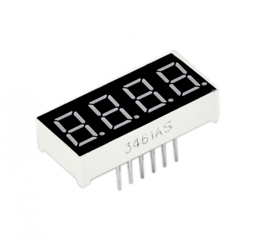
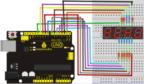
In this experiment, we use an Arduino to drive a common anode, 4-digit, 7-segment LED display. For LED display, current-limiting resistors are indispensable. There are two wiring method for Current-limiting resistor. One is to connect one resistor for each anode, 4 in totals for d1-d4 anode. An advantage for this method is that it requires fewer resistors, only 4. But it cannot maintain consistent brightness, 1 the brightest, 8, the least bright. Another method is to connect one resistor to each pin. It guarantees consistent brightness, but requires more resistors. In this experiment, we use 8 220Ω resistors (we use 220Ω resistors because no 100Ω resistor available. If you use 100Ω, the displaying will be brighter).
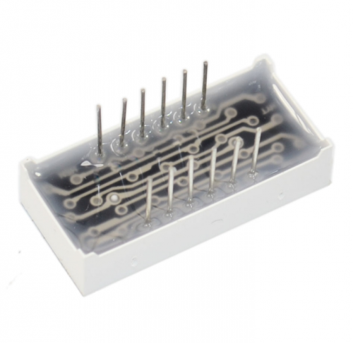
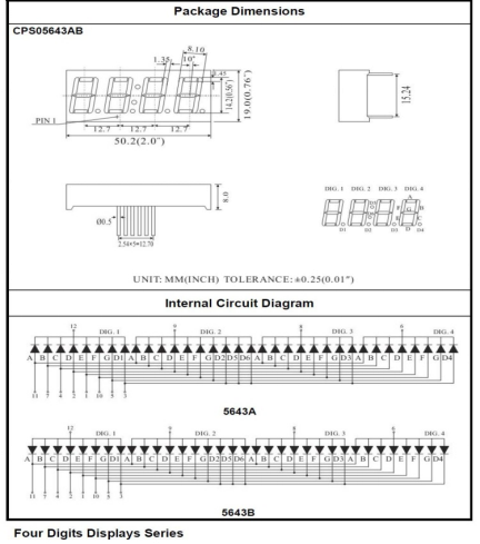
For 4-digit displays, there are 12 pins in total. When you place the decimal point downward (see below photo position), the pin on the lower left part is refer to as 1, the upper left part 12.
Manual for LED segment display
Sample Code:
// display 1234
	// select pin for cathode
	int a = 1;
	int b = 2;
	int c = 3;
	int d = 4;
	int e = 5;
	int f = 6;
	int g = 7;
	int dp = 8;
	// select pin for anode
	int d4 = 9;
	int d3 = 10;
	int d2 = 11;
	int d1 = 12;
	// set variable
	long n = 1230;
	int x = 100;
	int del = 55;  // fine adjustment for clock

	void setup()
	{
	  pinMode(d1, OUTPUT);
	  pinMode(d2, OUTPUT);
	  pinMode(d3, OUTPUT);
	  pinMode(d4, OUTPUT);
	  pinMode(a, OUTPUT);
	  pinMode(b, OUTPUT);
	  pinMode(c, OUTPUT);
	  pinMode(d, OUTPUT);
	  pinMode(e, OUTPUT);
	  pinMode(f, OUTPUT);
	  pinMode(g, OUTPUT);
	  pinMode(dp, OUTPUT);
	}
/////////////////////////////////////////////////////////////
void loop()
{
 Display(1, 1);
 Display(2, 2);
 Display(3, 3);
 Display(4, 4);

}
///////////////////////////////////////////////////////////////
void WeiXuan(unsigned char n)//
{
    switch(n)
     {
	case 1:
	  digitalWrite(d1,LOW);
 	  digitalWrite(d2, HIGH);
	  digitalWrite(d3, HIGH);
	  digitalWrite(d4, HIGH);
	 break;
	 case 2:
	  digitalWrite(d1, HIGH);
 	  digitalWrite(d2, LOW);
	  digitalWrite(d3, HIGH);
	  digitalWrite(d4, HIGH);
	    break;
	  case 3:
	    digitalWrite(d1,HIGH);
 	   digitalWrite(d2, HIGH);
	   digitalWrite(d3, LOW);
	   digitalWrite(d4, HIGH);
	    break;
	  case 4:
	   digitalWrite(d1, HIGH);
 	   digitalWrite(d2, HIGH);
	   digitalWrite(d3, HIGH);
	   digitalWrite(d4, LOW);
	    break;
        default :
           digitalWrite(d1, HIGH);
	   digitalWrite(d2, HIGH);
	   digitalWrite(d3, HIGH);
	   digitalWrite(d4, HIGH);
        break;
	  }
}
void Num_0()
{
  digitalWrite(a, HIGH);
  digitalWrite(b, HIGH);
  digitalWrite(c, HIGH);
  digitalWrite(d, HIGH);
  digitalWrite(e, HIGH);
  digitalWrite(f, HIGH);
  digitalWrite(g, LOW);
  digitalWrite(dp,LOW);
}
void Num_1()
{
  digitalWrite(a, LOW);
  digitalWrite(b, HIGH);
  digitalWrite(c, HIGH);
  digitalWrite(d, LOW);
  digitalWrite(e, LOW);
  digitalWrite(f, LOW);
  digitalWrite(g, LOW);
  digitalWrite(dp,LOW);
}
void Num_2()
{
  digitalWrite(a, HIGH);
  digitalWrite(b, HIGH);
  digitalWrite(c, LOW);
  digitalWrite(d, HIGH);
  digitalWrite(e, HIGH);
  digitalWrite(f, LOW);
  digitalWrite(g, HIGH);
  digitalWrite(dp,LOW);
}
void Num_3()
{
  digitalWrite(a, HIGH);
  digitalWrite(b, HIGH);
  digitalWrite(c, HIGH);
  digitalWrite(d, HIGH);
  digitalWrite(e, LOW);
  digitalWrite(f, LOW);
  digitalWrite(g, HIGH);
  digitalWrite(dp,LOW);
}
void Num_4()
{
  digitalWrite(a, LOW);
  digitalWrite(b, HIGH);
  digitalWrite(c, HIGH);
  digitalWrite(d, LOW);
  digitalWrite(e, LOW);
  digitalWrite(f, HIGH);
  digitalWrite(g, HIGH);
  digitalWrite(dp,LOW);
}
void Num_5()
{
  digitalWrite(a, HIGH);
  digitalWrite(b, LOW);
  digitalWrite(c, HIGH);
  digitalWrite(d, HIGH);
  digitalWrite(e, LOW);
  digitalWrite(f, HIGH);
  digitalWrite(g, HIGH);
  digitalWrite(dp,LOW);
}
void Num_6()
{
  digitalWrite(a, HIGH);
  digitalWrite(b, LOW);
  digitalWrite(c, HIGH);
  digitalWrite(d, HIGH);
  digitalWrite(e, HIGH);
  digitalWrite(f, HIGH);
  digitalWrite(g, HIGH);
  digitalWrite(dp,LOW);
}
void Num_7()
{
  digitalWrite(a, HIGH);
  digitalWrite(b, HIGH);
  digitalWrite(c, HIGH);
  digitalWrite(d, LOW);
  digitalWrite(e, LOW);
  digitalWrite(f, LOW);
  digitalWrite(g, LOW);
  digitalWrite(dp,LOW);
}
void Num_8()
{
  digitalWrite(a, HIGH);
  digitalWrite(b, HIGH);
  digitalWrite(c, HIGH);
  digitalWrite(d, HIGH);
  digitalWrite(e, HIGH);
  digitalWrite(f, HIGH);
  digitalWrite(g, HIGH);
  digitalWrite(dp,LOW);
}
void Num_9()
{
  digitalWrite(a, HIGH);
  digitalWrite(b, HIGH);
  digitalWrite(c, HIGH);
  digitalWrite(d, HIGH);
  digitalWrite(e, LOW);
  digitalWrite(f, HIGH);
  digitalWrite(g, HIGH);
  digitalWrite(dp,LOW);
}
void Clear()  // clear the screen
{
  digitalWrite(a, LOW);
  digitalWrite(b, LOW);
  digitalWrite(c, LOW);
  digitalWrite(d, LOW);
  digitalWrite(e, LOW);
  digitalWrite(f, LOW);
  digitalWrite(g, LOW);
  digitalWrite(dp,LOW);
}
void pickNumber(unsigned char n)// select number
{
  switch(n)
  {
   case 0:Num_0();
   break;
   case 1:Num_1();
   break;
   case 2:Num_2();
   break;
   case 3:Num_3();
   break;
   case 4:Num_4();
   break;
   case 5:Num_5();
   break;
   case 6:Num_6();
   break;
   case 7:Num_7();
   break;
   case 8:Num_8();
   break;
   case 9:Num_9();
   break;
   default:Clear();
   break;
  }
}
void Display(unsigned char x, unsigned char Number)//  take x as coordinate and display number
{
  WeiXuan(x);
  pickNumber(Number);
 delay(1);
 Clear() ; // clear the screen
}
Result:
Download the above code to the controller board and see the result.
The experiment result displays 1234 on the display.
Note: if it’s not displaying correctly, check the wiring.
Thank you.
Project 15: 8*8 LED Matrix
Introduction: With low-voltage scanning, LED dot-matrix displays have advantages such as power saving, long service life, low cost, high brightness, wide angle of view, long visual range, waterproof, and numerous specifications. LED dot-matrix displays can meet the needs of different applications and thus have a broad development prospect. This time, we will conduct an LED dot-matrix experiment to experience its charm firsthand.
Hardware required:
- 1 * Uno board
- 1 * 8*8 dot-matrix
- 8 * Resistor (220Ω)
- 1 * Breadboard
- 2 * 74HC595
- 1 * USB cable
- Jumper wires
Connection :
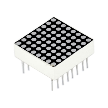
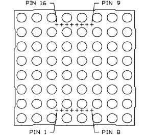
The external view of a dot-matrix is shown as follows:
The display principle of the 8*8 dot-matrix:
The 8*8 dot-matrix is made up of sixty-four LEDs, and each LED is placed at the cross point of a row and a column. When the electrical level of a certain row is 1 and the electrical level of a certain column is 0, the corresponding LED will light up. If you want to light the LED on the first dot, you should set pin 9 to high level and pin 13 to low level. If you want to light LEDs on the first row, you should set pin 9 to high level and pins 13, 3, 4, 10, 6, 11, 15 and 16 to low level. If you want to light the LEDs on the first column, set pin 13 to low level and pins 9, 14, 8, 12, 1, 7, 2 and 5 to high level.
The internal view of a dot-matrix is shown as follows:
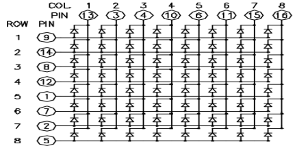
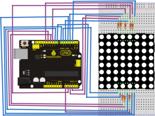
The principle of 74HC595 has been previously illustrated. One chip is used to control the rows of the dot-matrix while the other chip is used to control the columns.
Connect circuit as shown in the following diagram:
Sample Code for Displaying “0”:
// set an array to store character of “0”
unsigned char Text[]={0x00,0x1c,0x22,0x22,0x22,0x22,0x22,0x1c};
void Draw_point(unsigned char x,unsigned char y)// point drawing function
{ clear_();
   digitalWrite(x+2, HIGH);
   digitalWrite(y+10, LOW);
   delay(1);
}
void show_num(void)// display function, call point drawing function
{
  unsigned char i,j,data;
  for(i=0;i<8;i++)
  {
    data=Text[i];
    for(j=0;j<8;j++)
    {
      if(data & 0x01)Draw_point(j,i);
      data>>=1;
    }
  }
}
void setup(){
int i = 0 ;
for(i=2;i<18;i++)
 {
   pinMode(i, OUTPUT);
  }
  clear_();
}
void loop()
{ show_num();
}
void clear_(void)// clear screen
{for(int i=2;i<10;i++)
  digitalWrite(i, LOW);
  for(int i=0;i<8;i++)
  digitalWrite(i+10, HIGH);
}
Result:
Burn the program into Uno board The dot-matrix will display 0.
Projects of Modules
Project 1: LED Blinking
Introduction:
This project is easier and you can make LED blink simply by modifying the codes a bit.
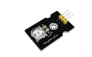
Hardware Required:
- UNO Board*1
- USB Cable*1
- Piranha LED Module*1
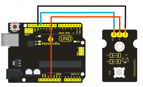
- Dupont Line*3
Sample Code:
 int led = 13;

// the setup routine runs once when you press reset:
void setup() {
  // initialize the digital pin as an output.
  pinMode(led, OUTPUT);
}

// the loop routine runs over and over again forever:
void loop() {
  digitalWrite(led, HIGH);   // turn the LED on (HIGH is the voltage level)
  delay(1000);               // wait for a second
  digitalWrite(led, LOW);    // turn the LED off by making the voltage LOW
  delay(1000);               // wait for a second
}
Result:
Upload the codes to UNO board and then you can see piranha LED and L light on the board are blinking together with an interval of one second.
Project 2: Active Buzzer Module
Introduction:
This project uses the same codes as Project 1’s, and then the buzzer will ring for one second and stop for one second.
Hardware Required:
- UNO Board*1
- USB Cable*1
- Active Buzzer Module*1
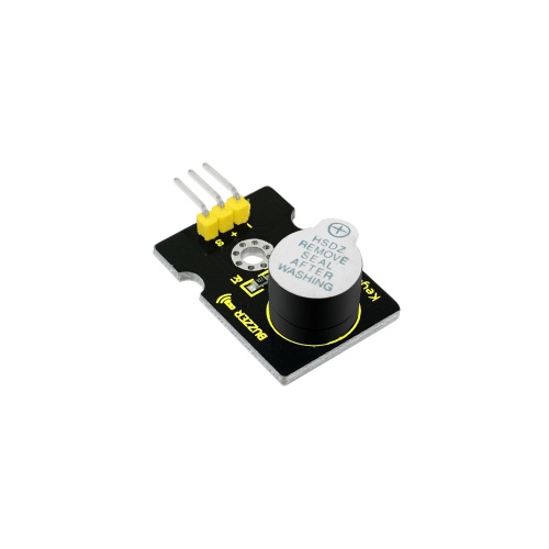
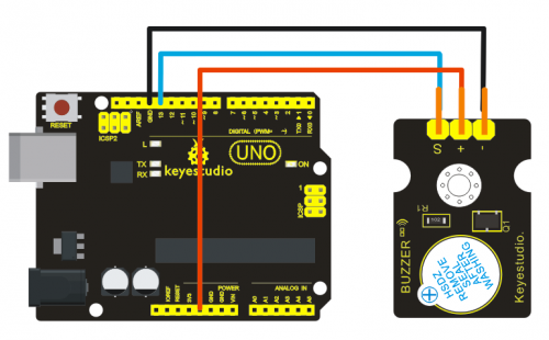
- Dupont Line*3
Sample Code:
int led = 13;

// the setup routine runs once when you press reset:
void setup() {
  // initialize the digital pin as an output.
  pinMode(led, OUTPUT);
}

// the loop routine runs over and over again forever:
void loop() {
  digitalWrite(led, HIGH);   // turn the LED on (HIGH is the voltage level)
  delay(1000);               // wait for a second
  digitalWrite(led, LOW);    // turn the LED off by making the voltage LOW
  delay(1000);               // wait for a second
}
Result:
After uploading the codes to UNO board, you can hear the buzzer ringing and see the L light blinking at the same time with an interval of one second.
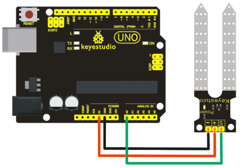
Project 3: Soil Module
Introduction:
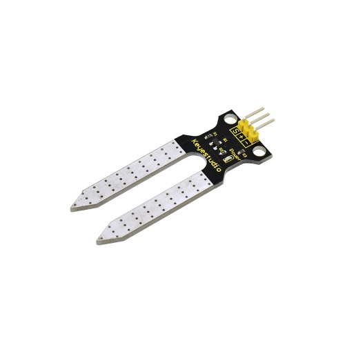
Soil Sensor is an easy moisture sensor detecting the moisture of soil. If soil is lack of water, the output analog value decreases; if not, the value increases.
This sensor detects the moisture by reading out the current change between two electrodes.
It uses two probes to make current flow through soil (as a resistor), and then read out the value to know quantity of moisture. When water is enough, soil can conduct electricity more easily(decreasing resistance); when lack of water, the electrical conductivity of soil is bad (increasing resistance).
Hardware Required:
- UNO Board*1
- USB Cable*1
- Soil Sensor Module*1
- Soil for Testing*1
- Dupont Line*3
Sample Code:
void setup() {
  Serial.begin(9600);
}

void loop() {
  int sensorValue = analogRead(A0);
  Serial.println(sensorValue, DEC);
}
Result:
After uploading the codes to UNO board, insert the sensor into soil of different humidity, and you can see different analog value on the serial port. When the humidity increases, analog value also increases; otherwise, the value decreases.
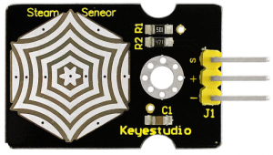
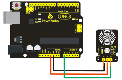
Project 4: Steam Sensor
Introduction:
When there is drop or vapor adhered to sensing point of vapor sensor, MCU will get a feedback of analog signal from S signal pin of the sensor. You can read out the value from MCU to deduce whether it rains.
Hardware Required:
- UNO Board*1
- USB Cable*1
- Steam Sensor*1
- Dupont Line*3
Sample Code:
void setup() {
  // initialize serial communication at 9600 bits per second:
  Serial.begin(9600);
}

// the loop routine runs over and over again forever:
void loop() {
  // read the input on analog pin 0:
  int sensorValue = analogRead(A0);
  // print out the value you read:
  Serial.println(sensorValue);
  delay(1);        // delay in between reads for stability
}
Result:
After uploading the codes to UNO board, open serial monitor, and you can see current value. Add drop on the sensing point and the analog value increases.
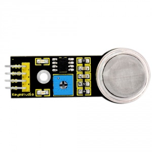
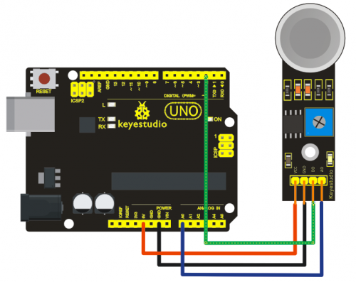
Project 5: MQ 135 Gas Sensor
Introduction:
MQ135 adopts SnO2 as its gas sensitive material because SnO2 has low electrical conductivity in the clean air. So when it surrounded by polluted air, the electrical conductivity of MQ135 will increase with the increase of pollutants, and the change in electrical conductivity can be converted to corresponding output signal.
MQ135 has a high sensitivity to ammonia, sulfide, benzene vapor, smoke and other harmful gas. It can detect various harmful gases, making it a cost-effective choice suitable for multiple applications.
Hardware Required:
- UNO Board*1
- USB Cable*1
- MQ135 Gas Sensor*1
- Dupont Line*4
Sample Code:
const int buttonPin = 2;     // the number of the pushbutton pin
const int ledPin =  13;      // the number of the LED pin

// variables will change:
int buttonState = 0;         // variable for reading the pushbutton status

void setup() {
  // initialize the LED pin as an output:
  pinMode(ledPin, OUTPUT);
  // initialize the pushbutton pin as an input:
  pinMode(buttonPin, INPUT);
  Serial.begin(9600);
}

void loop(){
  // read the state of the pushbutton value:
  buttonState = digitalRead(buttonPin);

  // check if the pushbutton is pressed.
  // if it is, the buttonState is HIGH:
  if (buttonState == HIGH) {
    // turn LED on:
    digitalWrite(ledPin, HIGH);
  }
  else {
    // turn LED off:
    digitalWrite(ledPin, LOW);
  }
}
Result:
After uploading the codes to UNO board, adjust the sensitivity of the sensor through potentiometer. Light up a lighter close to the sensor, and you can see the analog value increases, LED on the sensor is on but L light on UNO board is off.
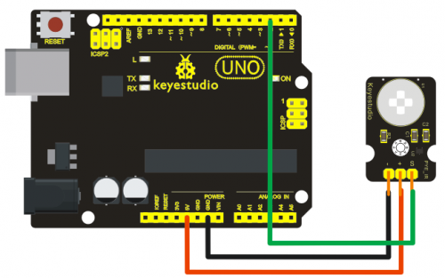
Project 6: PIR Motion Sensor
Introduction:
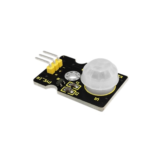
PIR Motion Sensor is an instrument converting IR into electrical signal with non-touch sensing. It is composed of detecting unit, Fresnel lens, interference filter , adaptor of field effect transistor and est.
It senses IR with pyroelectric effect which means when electron of heated object moves from high temperature to low temperature, the object will produce current or its electric charge will pile up. First the lens receives IR from testing object; next the sensor converts IR into electrical signal ; finally, the circuit will process the signal.
Hardware Required:
- UNO Board*1
- USB Cable*1
- PIR Motion Sensor*1
- Dupont Line*3
Sample Code:
int IRswitch = 2; //signal output of sensor;
int led = 13; //input of signal indicator;
boolean val = false; //reading out signal in real time;
void setup()
{
pinMode(IRswitch,INPUT);
pinMode(led,OUTPUT); //defining ports;
}
void loop()
{
val = digitalRead(IRswitch); //reading output level;
if(val)
digitalWrite(led,HIGH); //the LED lights up, when there is someone moving in detecting range;
else
http://keyes-arduino.taobao.com
digitalWrite(led,LOW); //all going well, LED off;
delay(10); //delaying for a moment, making LED stable;
}
Result:
After uploading the codes to UNO R3 board, if there is someone moving around the sensor, the L light on UNO R3 board is on; if none, L light is on for some time and then off.
Project 7: GUVA-S12SD 3528 Ultraviolet Sensor
Introduction:
PIR Motion Sensor is an instrument converting IR into electrical signal with non-touch sensing. It is composed of detecting unit, Fresnel lens, interference filter , adaptor of field effect transistor and est.
It senses IR with pyroelectric effect which means when electron of heated object moves from high temperature to low temperature, the object will produce current or its electric charge will pile up. First the lens receives IR from testing object; next the sensor converts IR into electrical signal ; finally, the circuit will process the signal.
Hardware Required:
- UNO Board*1
- USB Cable*1
- Ultraviolet Sensor*1
- Dupont Line*3
Sample Code:
void setup() {
  // initialize serial communication at 9600 bits per second:
  Serial.begin(9600);
}

// the loop routine runs over and over again forever:
void loop() {
  // read the input on analog pin 0:
  int sensorValue = analogRead(A0);
  // print out the value you read:
  Serial.println(sensorValue);
  delay(1);        // delay in between reads for stability
}
Result:
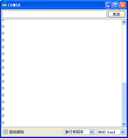
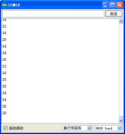
After uploading the codes, open serial monitor, and you can see current value is 0 when no sunlight. When putting the sensor under sunlight, you can see the intensity of sunlight displaying on the monitor.
Project 8: TEMT6000 Ambient Light Sensor
Introduction:
TEMT6000 is an audion photoconductive sensor. Its illumination intensity is proportional to current of base electrode. It is very easy to use. Just connect the base electrode to input of analog voltage. You can know current intensity by detecting the voltage value.
Hardware Required:
- UNO Board*1
- USB Cable*1
- Ambient Light Sensor*1
- Dupont Line*3
Sample Code:
void setup() {
  // initialize serial communication at 9600 bits per second:
  Serial.begin(9600);
}

// the loop routine runs over and over again forever:
void loop() {
  // read the input on analog pin 0:
  int sensorValue = analogRead(A0);
  // print out the value you read:
  Serial.println(sensorValue);
  delay(1);        // delay in between reads for stability
}
Result:
After uploading the codes, open serial monitor, and you can see the value decrease with intensity decreasing. Otherwise, the value increases.
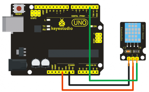
Project 9: DHT11 Temperature and Humidity Sensor
Introduction:
This DHT11 Temperature and Humidity Sensor features calibrated digital signal output with the temperature and humidity sensor complex. Its technology ensures high reliability and excellent long-term stability. It has excellent quality, fast response, anti-interference ability and high cost performance advantages.The single-wire serial interface system is integrated to make it quick and easy.
Hardware Required:
- UNO Board*1
- USB Cable*1
- DHT11 Temperature and Humidity Sensor*1
- Dupont Line*3
Sample Code:
int DHpin = 8;
byte dat[5];
byte read_data()
{
   byte data;
  for(int i=0; i<8; i++)
  {
    if(digitalRead(DHpin) == LOW)
    {
      while(digitalRead(DHpin) == LOW);  //waiting for 50us;
      delayMicroseconds(30);  // estimating the duration of high level to decide 0 or 1;
      if(digitalRead(DHpin) == HIGH)
      data |= (1<<(7-i));  //high-order forward, low-order backward
       while(digitalRead(DHpin) == HIGH);  //‘1’,waiting for receiving next one;
    }
  }
     return data;
}
void start_test()
{
  digitalWrite(DHpin,LOW);  //lower bus to delivery START signal;
  delay(30);  //delayed time should be more than 18ms,so that DHT11 can detect START signal;
  digitalWrite(DHpin,HIGH);
  delayMicroseconds(40);  //waiting for DHT11 to respond;
 pinMode(DHpin,INPUT);
 while(digitalRead(DHpin) == HIGH);
 delayMicroseconds(80);  //DHT11 giving out respond,lowering bus at 80us;
 if(digitalRead(DHpin) == LOW);
 delayMicroseconds(80);  //DHT11 pulling up bus at80us and then sending out data;
 for(int i=0;i<4;i++)   //receiving data of temperature and humidity without consideration of check bit;
 dat[i] = read_data();
pinMode(DHpin,OUTPUT);
digitalWrite(DHpin,HIGH);  //after sending data once, releasing bus, waiting for next time//START signal;
}
void setup()
{
   Serial.begin(9600);
   pinMode(DHpin,OUTPUT);
}
void loop()
{
   start_test();
   Serial.print("Current humdity = ");
   Serial.print(dat[0], DEC);  //displaying integer bit of humidity;
   Serial.print('.');
   Serial.print(dat[1],DEC);  //displaying decimals bit of humidity;
   Serial.println('%');
   Serial.print("Current temperature = ");
   Serial.print(dat[2], DEC);  //displaying integer bit of temperature;
   Serial.print('.');
   Serial.print(dat[3],DEC);  //displaying decimals bit of temperature;
   Serial.println('C');
  delay(700);

}
Result:
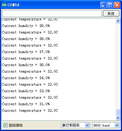
After uploading the codes, you can see current temperature and humidity on serial monitor.
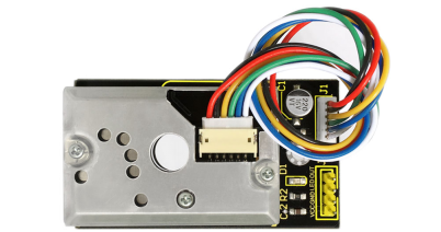
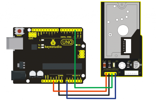
Project 10: GP2Y10 Dust Sensor
Introduction:
GP2Y10 Dust Sensor uses Sharp optics sensing system which detects reflected light of dust with IR optics sensor. It can sense very tiny granule, such as cigarette and features low-power consumption and high resolution ratio.
Hardware Required:
- UNO Board*1
- USB Cable*1
- GP2Y10 Dust Sensor*1
- Dupont Line*4
Sample Code:
int dustPin=A0;
float dustVal=0;
int ledPower=2;
int delayTime=280;
int delayTime2=40;
float offTime=9680;
void setup(){
Serial.begin(9600);
pinMode(ledPower,OUTPUT);
pinMode(dustPin, INPUT);
}

void loop(){
// ledPower is any digital pin on the arduino connected to Pin 3 on the sensor
digitalWrite(ledPower,LOW);
delayMicroseconds(delayTime);
dustVal=analogRead(dustPin);
delayMicroseconds(delayTime2);
digitalWrite(ledPower,HIGH);
delayMicroseconds(offTime);
delay(1000);
if (dustVal>36.455)
Serial.println((float(dustVal/1024)-0.0356)*120000*0.035);
}
Result:
After uploading the codes, you can see the following value on serial monitor:
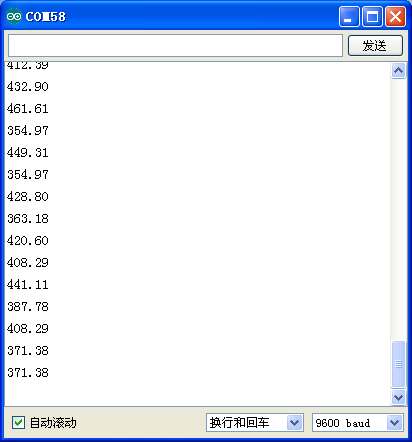
Data after testing in contrast to air quality:
3000 + = very bad
1050-3000 = bad
300-1050 = normal
150-300 = good
75-150 = very good
0-75 = tiptop
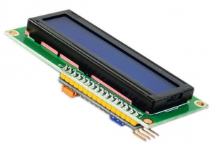
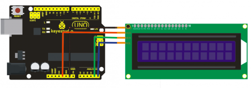
Project 11: I2C1602 Liquid Crystal Display Module
Introduction:
This module uses I2C communication mode to reduce the usage of I/O port of MCU. You can adjust contrast ratio of screen through potentiometer to get the optimal displaying effect.
Hardware Required:
- UNO Board*1
- USB Cable*1
- I2C1602 Liquid Crystal Display Module*1
- Dupont Line*4
Sample Code:
#include <LiquidCrystal_I2C.h>
#include <Wire.h>
LiquidCrystal_I2C lcd(0x27,16,2);  // set the LCD address to 0x27 for a 16 chars and 2
void setup()
{
  lcd.init();                      // initialize the lcd
  // Print a message to the LCD.
  lcd.backlight();
  lcd.print("Hello Arduino");
}
void loop()
{
}
Result:
After uploading the codes, you can see there is displaying “Hello Arduino”on the screen.
Project 12: Ambient Light Sensor to Control Brightness of LED
Introduction:
In this project, we use TEMT6000 ambient light sensor to control brightness of LED.
Hardware Required:
- UNO Board*1
- USB Cable*1
- Shield V5*1
- Piranha LED Module*1
- Ambient Light Sensor*1
- Dupont Line*Several
Circuit Connection:
Plug Shield V5 into UNO board and don’t misplace pins to avoid damaging the board.
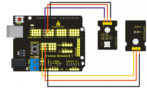
Sample Code:
void setup()
{
  pinMode(11,OUTPUT);          //choosing PWM digital output
}

void loop()
{
  int n = analogRead(A0);     //reading the value of A0 port(0-5V corresponding to 0-1204)
  analogWrite(11,n/4);         //maximum value of PWM is 255 so analog value n is divided by 4.
}
Result:
After uploading the codes, you can change the illumination intensity of the sensor to control the brightness of LED.
Project 13: Ultraviolet Sensor to Alarm
Introduction:
When ultraviolet sensor receives ultraviolet ray up to a certain value, the buzzer rings.
Hardware Required:
- UNO Board*1
- USB Cable*1
- Shield V5*1
- Buzzer Module*1
- Ultraviolet Sensor*1
- Dupont Line*Several
Circuit Connection:
Plug Shield V5 into UNO board and don’t misplace pins to avoid damaging the board.
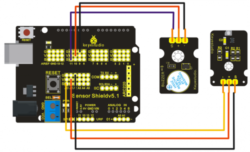
Sample Code:
int ON = 11;
// the setup routine runs once when you press reset:
void setup() {
  // initialize serial communication at 9600 bits per second:
  pinMode(ON, OUTPUT);
  Serial.begin(9600);
}

// the loop routine runs over and over again forever:
void loop() {
  // read the input on analog pin 0:
  int sensorValue = analogRead(A0);
  int n;
  // print out the value you read:
  if(sensorValue>=20)
    {
      for(n=0;n<8;n++)
      {
        digitalWrite(ON, HIGH);
        delay(1000);
        digitalWrite(ON, LOW);
        delay(500);
      }
    }
  else
   {
     digitalWrite(ON, LOW);
   }
  Serial.println(sensorValue);
  delay(1);        // delay in between reads for stability
}
Result:
After uploading the codes, you can see when the value is equal to or more than 20, the buzzer rings for 1 second and stop for 0.5 second, circulating 8 times.
Project 14: Displaying Temperature and Humidity on LCD
Introduction:
In this project, we use DHT11 temperature and humidity sensor to measure current temperature and humidity, displaying them on LCD1602.
Hardware Required:
- UNO Board*1
- USB Cable*1
- Shield V5*1
- DHT11 Temperature and Humidity Sensor*1
- LCD1602*1
- Dupont Line*Several
Circuit Connection:
Plug Shield V5 into UNO board and don’t misplace pins to avoid damaging the board.
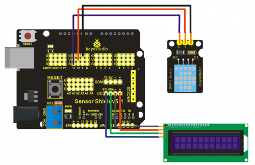
Sample Code:
#include <Wire.h>
#include <LiquidCrystal_I2C.h>
#include "DHT.h"
LiquidCrystal_I2C lcd(0x27,20,4);
#define DHTPIN 11     // what pin we're connected to

// Uncomment whatever type you're using!
#define DHTTYPE DHT11   // DHT 11
//#define DHTTYPE DHT22   // DHT 22  (AM2302)
//#define DHTTYPE DHT21   // DHT 21 (AM2301)

DHT dht(DHTPIN, DHTTYPE);

void setup() {
  Serial.begin(9600);
  Serial.println("DHTxx test!");

  dht.begin();

  lcd.init();
  lcd.init();
  lcd.backlight();
   lcd.clear();
   lcd.setCursor(0,0);
   lcd.print("DHT-11 test!");
}

void loop() {
  // Reading temperature or humidity takes about 250 milliseconds!
  // Sensor readings may also be up to 2 seconds 'old' (its a very slow sensor)
  float h = dht.readHumidity();
  float t = dht.readTemperature();

  lcd.clear();
    if (isnan(t) || isnan(h)) {
    Serial.println("Failed to read from DHT");
    lcd.setCursor(0,0);
    lcd.print("Failed DHT");
  } else {
    Serial.print("Humidity: ");
    lcd.setCursor(0,0);
    lcd.print("H:");
    Serial.print(h);
    lcd.setCursor(3,0);
    lcd.print(h);
    Serial.print(" %\t");
    lcd.setCursor(9,0);
    lcd.print("%");
    Serial.print("Temperature: ");
    lcd.setCursor(0,1);
    lcd.print("T:");
    Serial.print(t);
    lcd.setCursor(3,1);
    lcd.print(t);
    Serial.println(" *C");
    lcd.setCursor(8,1);
    lcd.print(" *C");
  }
  delay(200);
}
Result:
After adding the libraries and uploading the codes, you can see current temperature and humidity displayed on LCD1602.
Project 15: Integrated Project
Introduction:
This project will detect ambient light, ultraviolet ray, gas ,temperature and humidity with LED, buzzer, LCD1602, etc.
Hardware Required:
- UNO board*1
- Shield V5*1
- DHT11 Temperature and Humidity Sensor *1
- LCD1602*1
- Piranha LED*3
- TEMT6000 Ambient Light Sensor*1
- GUVA-S12SD 3528 Ultraviolet Sensor*1
- MQ 135 Gas Sensor*1
- GP2Y10 Dust Sensor*1
- Buzzer Module*1
- PIR Motion Sensor*1
- USB Cable*1
- Dupont Line*Several
Circuit Connection:
Plug Shield V5 into UNO board and don’t misplace pins to avoid damaging the board.
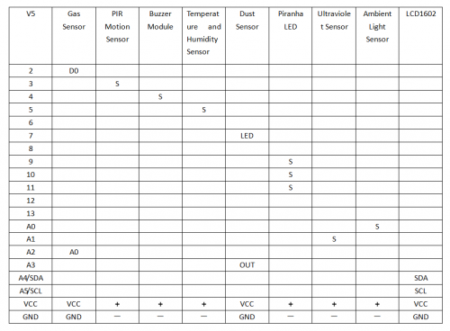
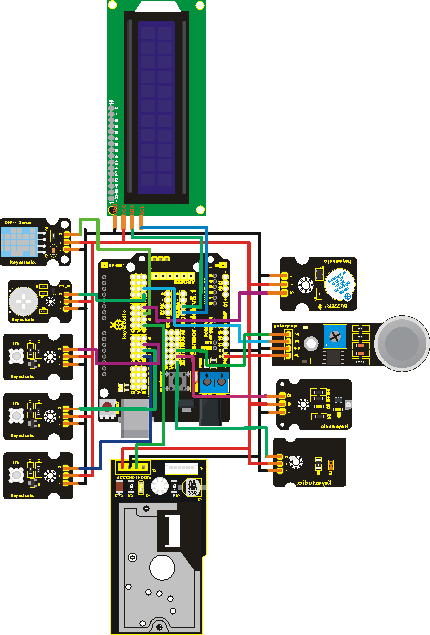
Sample Code:
#include <Wire.h>
#include <LiquidCrystal_I2C.h>
#include "DHT.h"
LiquidCrystal_I2C lcd(0x27,20,4);
#define DHTPIN 5     //defining DHT11digital ports
#define GP2Y_LED 7   //defining digital ports of Dust Sensor
#define GP2Y_OUT A3  //defining analog ports of Dust Sensor
#define GAS A2       //defining analog ports of Gas Sensor
#define GAS_D 2     //defining digital ports of Gas Sensor
#define S12SD A1    //defining analog ports of Ultraviolet Sensor
#define TEMT A0     //defining analog ports of Ambient Light Sensor
#define LED1 9      //defining digital ports of LED
#define LED2 10     //defining digital ports of LED
#define LED3 11     //defining digital ports of LED
#define BUZZ 4      //defining digital ports of Buzzer Module
#define PIR 3       //defining digital ports of PIR Motion Sensor
// Uncomment whatever type you're using!
#define DHTTYPE DHT11   // DHT 11
//#define DHTTYPE DHT22   // DHT 22  (AM2302)
//#define DHTTYPE DHT21   // DHT 21 (AM2301)
float dustVal=0;
int delayTime=280;
int delayTime2=40;
float offTime=9680;
int gasdigi = 1;//original value
boolean IR_val = false; //reading signal in real time of PIR Motion Sensor
int TEMT_val;           //reading signal in real time of TEMT6000Ambient Light Sensor
int S12SD_val;

DHT dht(DHTPIN, DHTTYPE);

void setup() {
  Serial.begin(9600);
  dht.begin();

  lcd.init();
  lcd.backlight();
  lcd.clear();
  lcd.setCursor(5,0);
  lcd.print("HELLO");
  delay(1000);

  pinMode(GP2Y_LED,OUTPUT);  pinMode(LED1,OUTPUT);pinMode(LED2,OUTPUT);pinMode(LED3,OUTPUT);
  pinMode(BUZZ,OUTPUT);pinMode(PIR,INPUT);pinMode(DHTPIN,OUTPUT);pinMode(GAS_D,INPUT);
  pinMode(GP2Y_OUT, INPUT);pinMode(GAS, INPUT);pinMode(S12SD, INPUT);pinMode(TEMT, INPUT);
  digitalWrite(LED1, LOW);
}

void loop()
{
    DHT11_FUNC();
    GP2Y_FUNC();
    PIR_FUNC();
    TEMT_FUNC();
    S12SD_FUNC();
}

void S12SD_FUNC()
{
  S12SD_val = analogRead(S12SD);
  Serial.println(S12SD_val);
  lcd.setCursor(10,1);
  lcd.print("R:");
  lcd.setCursor(12,1);
  lcd.print(S12SD_val*10);
  if(S12SD_val*10 >= 300)
    digitalWrite(BUZZ,HIGH);
  else
    digitalWrite(BUZZ,LOW);
}

void TEMT_FUNC()
{
  TEMT_val = analogRead(TEMT);
  Serial.println(TEMT_val);
  //analogWrite(LED1, map(analogRead(TEMT), 0 , 1023, 0, 255));
  analogWrite(LED1, map(analogRead(TEMT), 1023 , 0 , 255, 0));
}

void GP2Y_FUNC()
{
  digitalWrite(GAS_D, HIGH);
  digitalWrite(GP2Y_LED,LOW);
  delayMicroseconds(delayTime);
  dustVal=analogRead(GP2Y_OUT);
  delayMicroseconds(delayTime2);
  digitalWrite(GP2Y_LED,HIGH);
  delayMicroseconds(offTime);

  if (dustVal>36.455)
  Serial.println((float(dustVal/1024)-0.0356)*120000*0.035);
  lcd.setCursor(0,1);
  lcd.print("GP:");
  lcd.setCursor(3,1);
  lcd.print((float(dustVal/1024)-0.0356)*120000*0.035);

  gasdigi = digitalRead(GAS_D);
   if(gasdigi == 0)   digitalWrite(LED3,HIGH);
   else               digitalWrite(LED3,LOW);
}

void DHT11_FUNC()
{
    // Reading temperature or humidity takes about 250 milliseconds!
  // Sensor readings may also be up to 2 seconds 'old' (its a very slow sensor)
  float h = dht.readHumidity();
  float t = dht.readTemperature();

  lcd.clear();
  // check if returns are valid, if they are NaN (not a number) then something went wrong!
  if (isnan(t) || isnan(h))
  {
    lcd.setCursor(0,0);
    lcd.print("Failed DHT");
  }
  else
  {
    lcd.setCursor(0,0);
    lcd.print(h);
    lcd.setCursor(6,0);
    lcd.print("%");

    lcd.setCursor(8,0);
    lcd.print(t);
    lcd.setCursor(14,0);
    lcd.print("*C");
  }
}

void PIR_FUNC()
{
  IR_val = digitalRead(PIR); //reading output of high or low level;
  if(IR_val)
  digitalWrite(LED2,HIGH); //someone moving in detecting rage, LED on;
  else
  //http://keyes-arduino.taobao.com
  digitalWrite(LED2,LOW); //all going well, LED off;
  delay(10); //delaying for some time to make LED stable;
}
Result:
After uploading the codes, first you can see the data displayed on LCD1602. Displaying current humidity on top-left, current temperature on top-right; showing dust value on bottom-left, ultraviolet intensity on bottom-right.
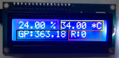
LED connected to D9 pin is changing with illumination intensity(the higher the intensity, the brighter the LED).
LED connected to D10 pin is on when someone moving in detecting range.
LED connected to D11 pin is on with gas sensor in low level. Sensitivity of the sensor can be adjusted by potentiometer.
After ultraviolet sensor receives ray, read analog value through A1 port. When the value is greater than 300 in the sentence if(S12SD_val*10 >= 300), the buzzer rings.
Resources
Video
http://video.keyestudio.com/KS0190/
Liraries Download:
https://fs.keyestudio.com/KS0190
