KS0481 Keyestudio Micro bit Honeycomb PS2 Joystick Module: Difference between revisions
Keyestudio (talk | contribs) (Created blank page) |
Keyestudio (talk | contribs) No edit summary |
||
| Line 1: | Line 1: | ||
<br>[[image:0481-1.png|thumb|600px|right|Keyestudio Micro bit Honeycomb PS2 Joystick Module]]<br> | |||
<br> | |||
==Description== | |||
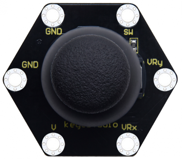
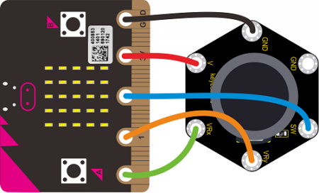
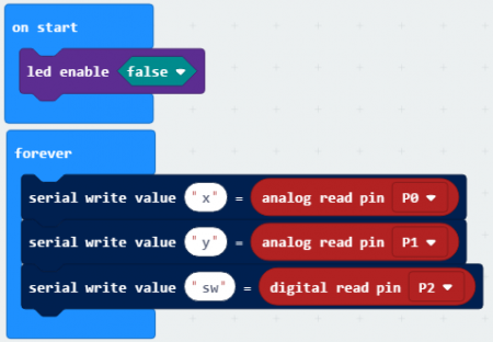
The keyestudio micro bit Honeycomb PS2 joystick module is fully compatible with micro bit control board. In the experiment, we connect the joystick module to the micro:bit control board using crocodile clip wire. There are 6 ports on the module, two GND ports are connected. When controlling it, we need to connect the VRx,VRy port to the analog port of the micro:bit control board, and the SW port to the digital port of the micro:bit control board. We can judge the working state of the joystick on the module by reading the two analog values and the high and low levels of a digital port. | |||
<span style=color:red> Special Note: When testing the SW port function, for some products, we need connect a resistor to SW interface (connect to VCC port after connecting a resistor), the port function is valid; otherwise SW port is invalid.</span> | |||
'''Technical Parameters'''<br> | |||
* Working voltage: DC 3.0-3.3V | |||
* Control port: analog port (VRx VRy) and digital port (SW) | |||
* Size: 40mm*45mm*31mm | |||
* Weight: 11.5g | |||
* Environmental attributes: ROHS | |||
'''Wiring Diagram'''<br> | |||
<br>[[File:0481-2.png|450px|frameless|thumb]]<br> | |||
'''Test Code'''<br> | |||
<br>[[File:0481-3.png|450px|frameless|thumb]]<br> | |||
'''Test Result'''<br> | |||
According to wiring diagram, upload test code successfully. After power-on, we can see the analog value of the X-Y-axis on the PS2 joystick module and the digital value of the SW port on the dot matrix of the micro:bit control board. | |||
Revision as of 11:56, 21 November 2019
Description
The keyestudio micro bit Honeycomb PS2 joystick module is fully compatible with micro bit control board. In the experiment, we connect the joystick module to the micro:bit control board using crocodile clip wire. There are 6 ports on the module, two GND ports are connected. When controlling it, we need to connect the VRx,VRy port to the analog port of the micro:bit control board, and the SW port to the digital port of the micro:bit control board. We can judge the working state of the joystick on the module by reading the two analog values and the high and low levels of a digital port. Special Note: When testing the SW port function, for some products, we need connect a resistor to SW interface (connect to VCC port after connecting a resistor), the port function is valid; otherwise SW port is invalid.
Technical Parameters
- Working voltage: DC 3.0-3.3V
- Control port: analog port (VRx VRy) and digital port (SW)
- Size: 40mm*45mm*31mm
- Weight: 11.5g
- Environmental attributes: ROHS
Test Result
According to wiring diagram, upload test code successfully. After power-on, we can see the analog value of the X-Y-axis on the PS2 joystick module and the digital value of the SW port on the dot matrix of the micro:bit control board.


