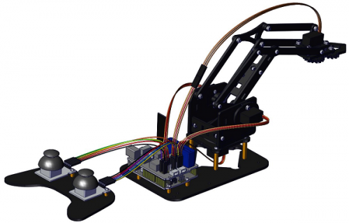
KS0198 Keyestudio 4DOF Robot Mechanical Arm Kit for Arduino DIY
Kit Overview
DIY is the activity of making or repairing things yourself, especially in your home. Historically, it has been popular all over the world since 1960s, making our routine life interesting.
Combined with STEM education, DIY products can greatly cultivate teenagers’ imagination and creativity.
Therefore, we Keyestudio R&D group rolls out an amazing 4DOF mechanical arm kit, which contributes to improving kids’hand-on ability, logical thinking and observation ability.
It is easy to build to say the least. In fact, the four servos of this robot arm are controlled by V4.0 control board and two joystick modules. What’s more, the detailed tutorials are provided for you even you are a starter.
For this mechanical robot arm, there are three methods to control. The first one is controller handle we provide(joystick modules), the second one is App; and the third one is wireless PS2 joystick module(not included in this kit).
I believe that you can’t help getting down with this kit.
Next, let’s get started.
Kit Features
You can check out these features:
- Detailed installation instructions
- Detailed debugging methods, starting Arduino from entry.
- Three controlling methods: Wired JoyStick Control; Phone Bluetooth Control; Wireless PS2 JoyStick Control.
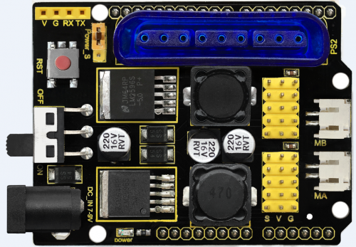
The parameters of keyestudio TB6612FNG motor/servo drive expansion board are as follows:
- VIN voltage: VIN = DC 7-15V
- VIN current: 5A
- Two-way 5V output: 5V/3A
- TB6612FNG: VIN input DC 7-15V; average drive current 1.2A; peak current 3.2A
- PS2 interface: compatible with Sony PS2 receiver, can be plugged directly into the expansion board.
- Dimensions: 73*53.34mm
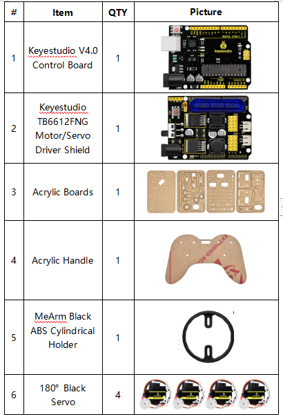
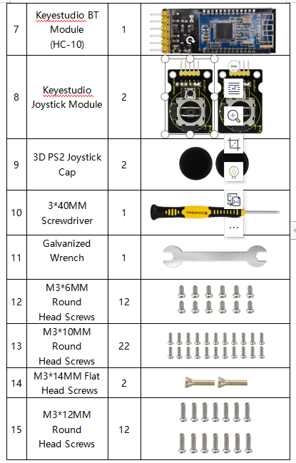
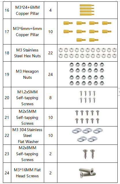
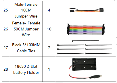
Kit List
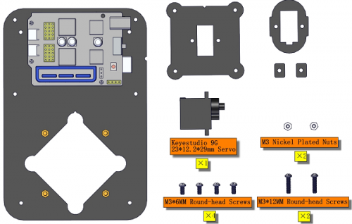
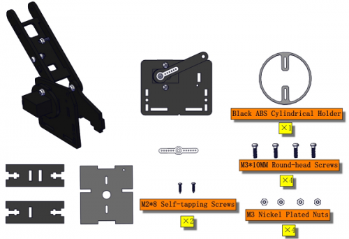
You can see a pretty beautiful packaging box for the arm kit, and inside the packaging you will find all the parts and screws listed below.
Note: Peel the plastic film off the board first when you install robotic arm.
Assembly Guide
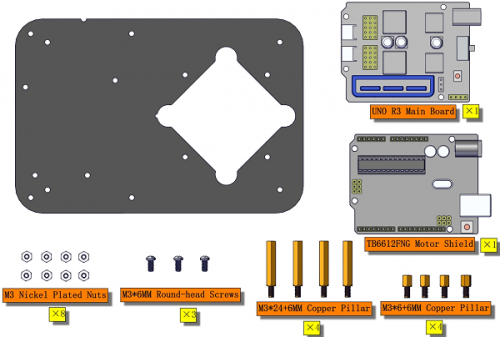
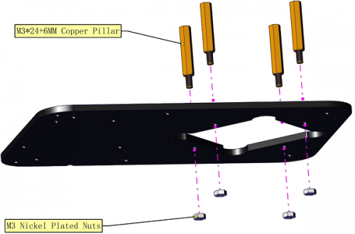
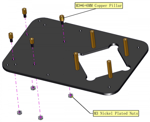
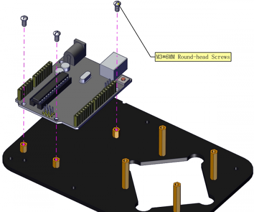
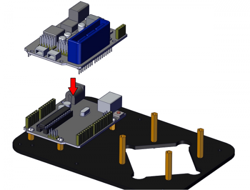
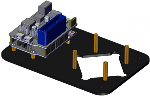
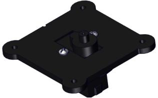
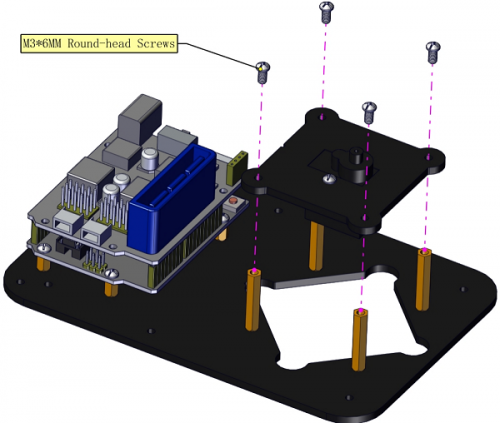
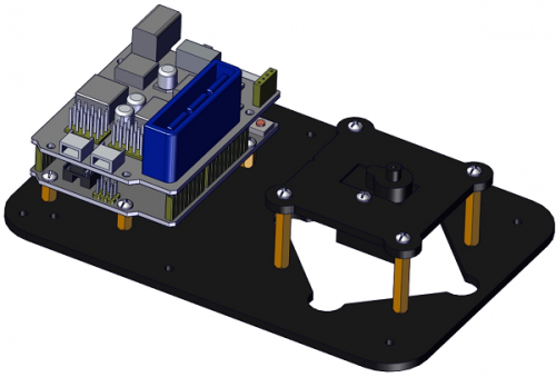
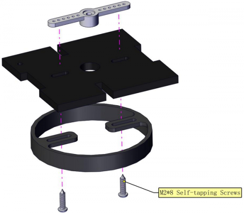
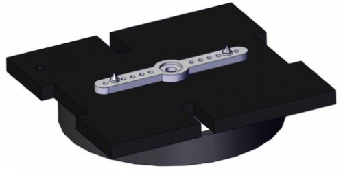
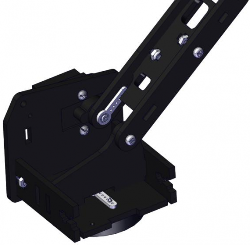
(1)Install the base of the robotic arm
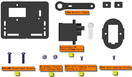
Components Needed:
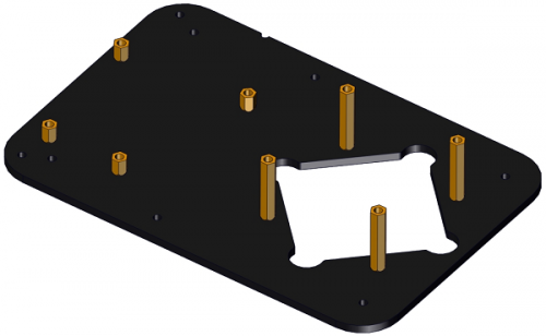
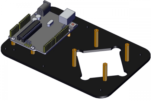
The base is installed successfully.
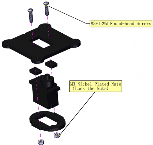
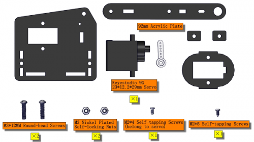
(2)Mount servos onto the base
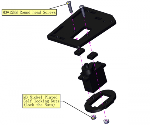
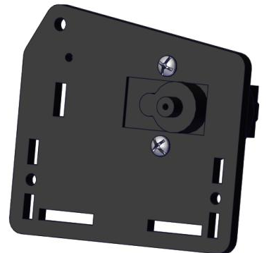
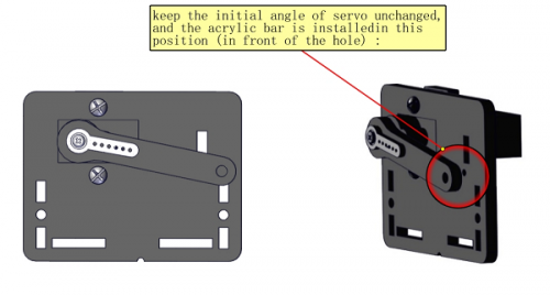
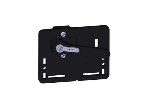
Assemble a servo(left) onto the left board
Initialize the left servo
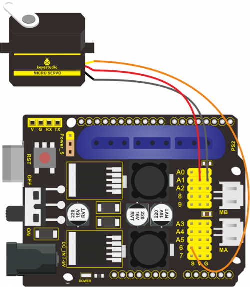
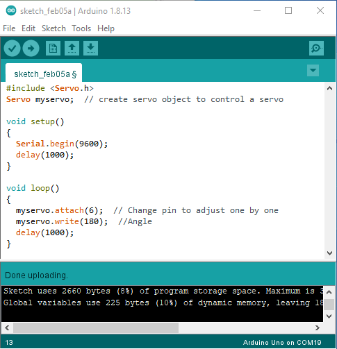
Attach this left servo to G, V and S(6)of TB6612FNG driver shield, upload the following code, plug in power and press the rest button on the V4.0 board. Then the left servo rotates to 180°
Test Code:
***************************************************************************
#include <Servo.h>
Servo myservo;  // create servo object to control a servo

void setup()
{
  Serial.begin(9600);
  delay(1000);
}

void loop()
{
  myservo.attach(6);  // Change pin to adjust one by one
  myservo.write(180);  //Angle
  delay(1000);
}
***************************************************************************
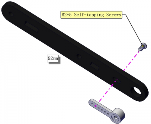
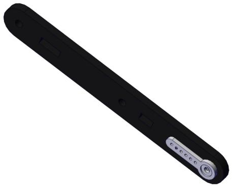
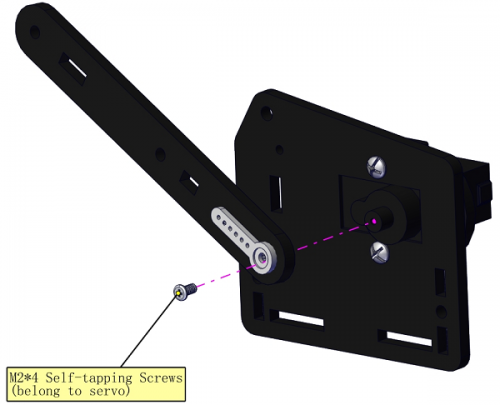
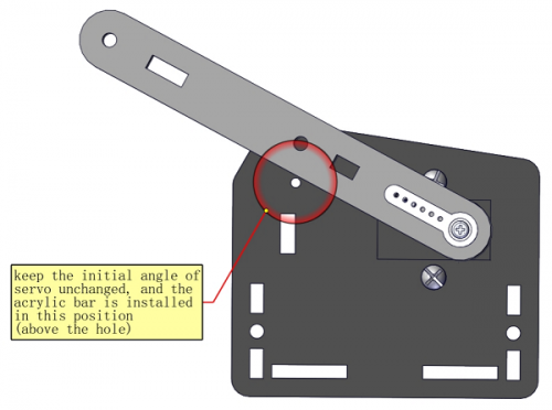
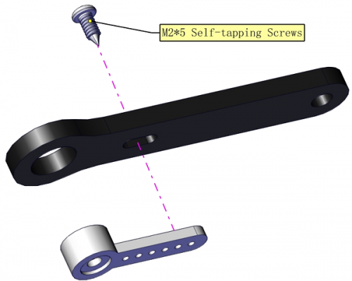
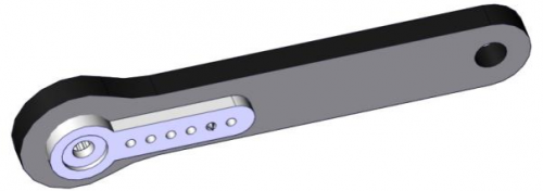
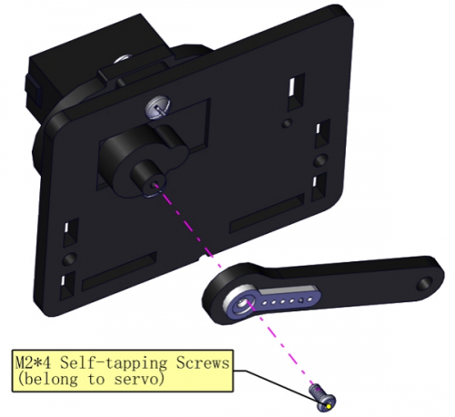
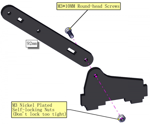
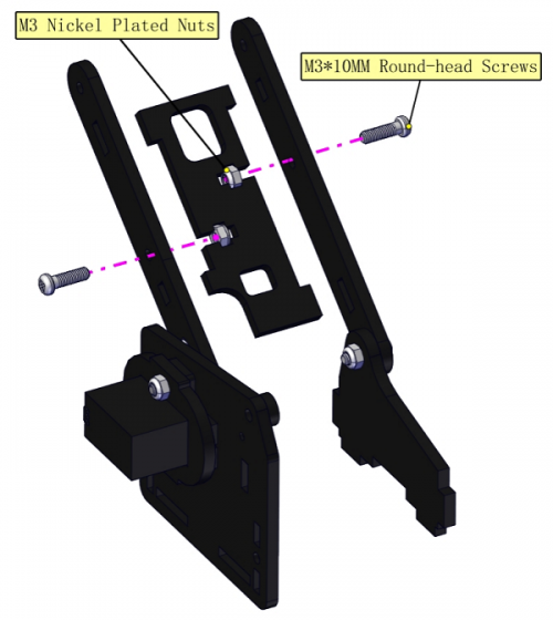
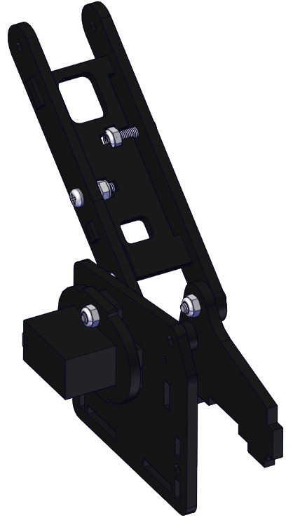
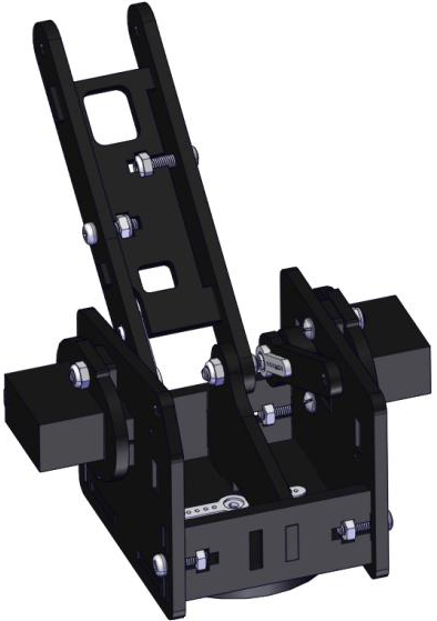
a.Fix the arm:
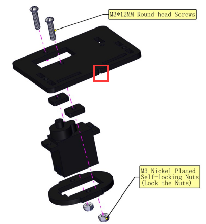
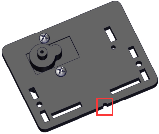
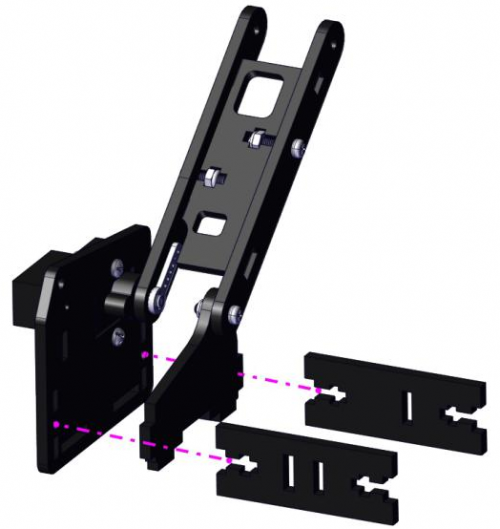
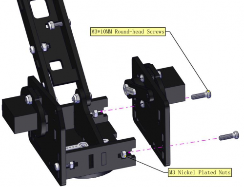
Mount a servo(right) onto the right board
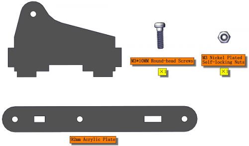
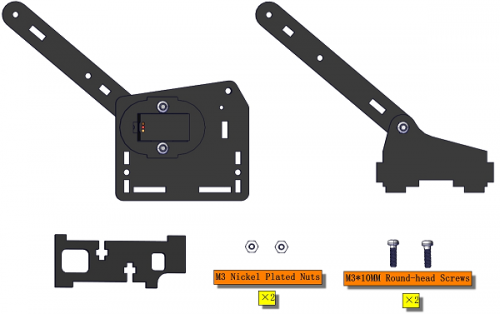
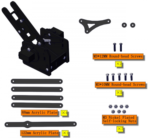
Components Needed
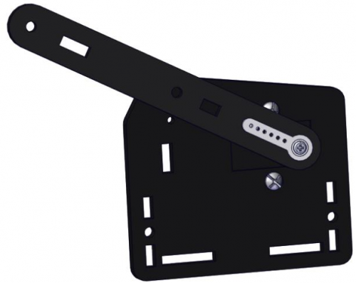
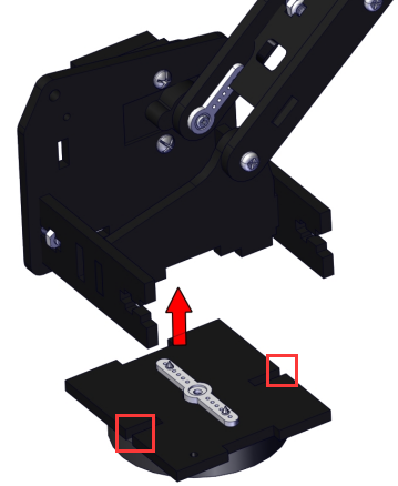
Note the breach direction of acrylic board
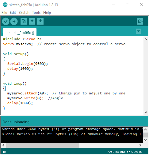
b.Initialize the right servo
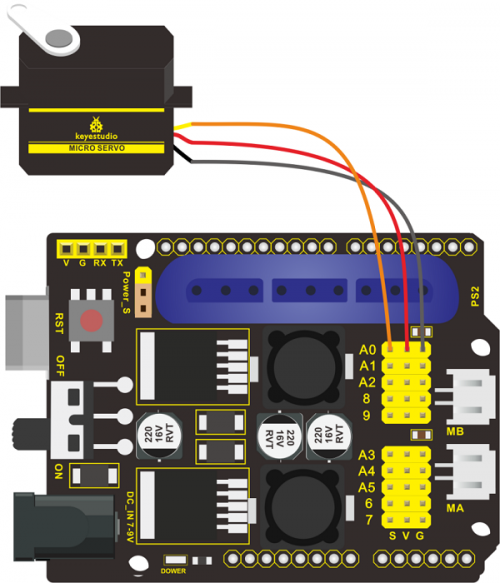
Attach this left servo to G, V and S(A0)of TB6612FNG driver shield, upload the following code, plug in power and press the rest button on the V4.0 board. Then the left servo rotates to 0°
Set the servo to 0°:
***************************************************************************
#include <Servo.h>
Servo myservo;  // create servo object to control a servo

void setup()
{
  Serial.begin(9600);
  delay(1000);
}

void loop()
{
  myservo.attach(A0);  // Change pin to adjust one by one
  myservo.write(0);  //Angle
  delay(1000);
}
***************************************************************************
