KS0310 Keyestudio Traffic Light Module (Black and Eco-friendly): Difference between revisions
Keyestudio (talk | contribs) |
Keyestudio (talk | contribs) No edit summary |
||
| Line 1: | Line 1: | ||
<br>[[File:Ks0310 traffic light module.png|600px|frameless|thumb]]<br> | |||
<br> | |||
== Introduction == | == Introduction == | ||
When learning the microcontroller, you may usually use three separate LEDs, namely red, green and yellow light, to simulate the traffic light blinking via external connection. <br> | When learning the microcontroller, you may usually use three separate LEDs, namely red, green and yellow light, to simulate the traffic light blinking via external connection. <br> | ||
| Line 9: | Line 9: | ||
This module is able to make some light-interactive works, fully compatible with Arduino microcontroller and raspberry pi system. | This module is able to make some light-interactive works, fully compatible with Arduino microcontroller and raspberry pi system. | ||
<br> | |||
== Specification == | == Specification == | ||
* Working Voltage: 3.3-5v | * Working Voltage: 3.3-5v | ||
* Interface Type: Digital | * Interface Type: Digital | ||
<br> | |||
== Connection Diagram == | == Connection Diagram == | ||
Here’s a wiring diagram combining the [http://www.keyestudio.com/ks0310.html traffic light module], four jumper wires and [ | Here’s a wiring diagram combining the [http://www.keyestudio.com/ks0310.html traffic light module], four jumper wires and [https://wiki.keyestudio.com/Ks0001_keyestudio_UNO_R3_BOARD keyestudio UNO board] | ||
<br> | |||
Connect the traffic light module to UNO board, R pin to Digital 5, Y pin to Digital 4, G pin to Digital 3, GND to GND. | Connect the traffic light module to UNO board, R pin to Digital 5, Y pin to Digital 4, G pin to Digital 3, GND to GND. | ||
<br>[[File:Ks0310-2.png| | <br>[[File:Ks0310-2.png|600px|frameless|thumb]]<br> | ||
<br> | |||
== Sample Code == | == Sample Code == | ||
Here is a simple Arduino example based on the circuit above. Copy and paste this into your [http://wiki.keyestudio.com/index.php/Download_Arduino_and_Install_Arduino_Driver Arduino IDE ], then upload! | Here is a simple Arduino example based on the circuit above. Copy and paste this into your [http://wiki.keyestudio.com/index.php/Download_Arduino_and_Install_Arduino_Driver Arduino IDE ], then upload! <br> | ||
<pre> | <pre> | ||
| Line 55: | Line 54: | ||
</pre> | </pre> | ||
<br> | |||
== Test Result == | == Test Result == | ||
Powered up and done uploading the code to the board, three LEDs on the module will automatically simulate the traffic light on and off. | Powered up and done uploading the code to the board, three LEDs on the module will automatically simulate the traffic light on and off. | ||
<br>[[File:KS0311图片1.png|600px|frameless|thumb]]<br> | <br>[[File:KS0311图片1.png|600px|frameless|thumb]]<br> | ||
<br> | |||
For further study, you can connect it to your PI. An example as below figure shown. | For further study, you can connect it to your PI. An example as below figure shown. | ||
<br>[[File:KS0310 (3).jpg|600px|frameless|thumb]]<br> | <br>[[File:KS0310 (3).jpg|600px|frameless|thumb]]<br> | ||
<br> | |||
== Resources == | == Resources == | ||
*'''Download the Datasheet:'''<br> | |||
https://drive.google.com/open?id=1DBJsa0jzaeCFapp9nCMQE9mW180w_ObA | |||
*'''Download the Code:'''<br> | |||
https://drive.google.com/open?id=1uR0PVw4-bLT3eyBMQ1KSB6KbOU133euX | |||
<br> | |||
== Buy From == | == Buy From == | ||
Like it? You can click the links below to get one now. Enjoy your time!<br> | |||
*[https://www.keyestudio.com/keyestudio-traffic-light-module-black-and-eco-friendly-for-arduino-p0446-p0446.html '''Official Website'''] | |||
*[https://www.aliexpress.com/store/product/Keyestudio-Traffic-Light-Module-Black-and-Eco-friendly-For-arduino/1452162_32857774489.html?spm=2114.12010615.8148356.1.5af638caRNADW2 '''From AliExpress''' ] | |||
[https://www.aliexpress.com/ | |||
*[https://www.ebay.com/itm/Keyestudio-LED-Traffic-Light-Sensor-Light-Traffic-Light-Module-R4J3-for-Arduino-/132559500573 '''From ebay'''] | |||
[https://www.ebay.com/itm/Keyestudio-LED-Traffic-Light-Sensor-Light-Traffic-Light-Module-R4J3-for-Arduino-/132559500573] | |||
Revision as of 11:20, 29 April 2019
Introduction
When learning the microcontroller, you may usually use three separate LEDs, namely red, green and yellow light, to simulate the traffic light blinking via external connection.
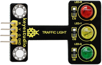
Convenient for wiring, we specially design this traffic light module. On the module, it has integrated three LEDs, like LED-R, LED-Y, LED-G.
This module is able to make some light-interactive works, fully compatible with Arduino microcontroller and raspberry pi system.
Specification
- Working Voltage: 3.3-5v
- Interface Type: Digital
Connection Diagram
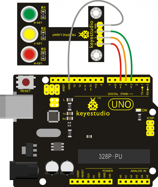
Here’s a wiring diagram combining the traffic light module, four jumper wires and keyestudio UNO board
Connect the traffic light module to UNO board, R pin to Digital 5, Y pin to Digital 4, G pin to Digital 3, GND to GND.

Sample Code
Here is a simple Arduino example based on the circuit above. Copy and paste this into your Arduino IDE , then upload!
int redled =5; // initialize digital pin 5.
int yellowled =4; // initialize digital pin 4.
int greenled =3; // initialize digital pin 3.
void setup()
{
pinMode(redled, OUTPUT);// set the pin with red LED as “output”
pinMode(yellowled, OUTPUT); // set the pin with yellow LED as “output”
pinMode(greenled, OUTPUT); // set the pin with green LED as “output”
}
void loop()
{
digitalWrite(greenled, HIGH);//// turn on green LED
delay(5000);// wait 5 seconds
digitalWrite(greenled, LOW); // turn off green LED
for(int i=0;i<3;i++)// blinks for 3 times
{
delay(500);// wait 0.5 seconds
digitalWrite(yellowled, HIGH);// turn on yellow LED
delay(500);// wait 0.5 seconds
digitalWrite(yellowled, LOW);// turn off yellow LED
}
delay(500);// wait 0.5 seconds
digitalWrite(redled, HIGH);// turn on red LED
delay(5000);// wait 5 seconds
digitalWrite(redled, LOW);// turn off red LED
}
Test Result
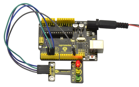
Powered up and done uploading the code to the board, three LEDs on the module will automatically simulate the traffic light on and off.

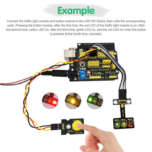
For further study, you can connect it to your PI. An example as below figure shown.

Resources
- Download the Datasheet:
https://drive.google.com/open?id=1DBJsa0jzaeCFapp9nCMQE9mW180w_ObA
- Download the Code:
https://drive.google.com/open?id=1uR0PVw4-bLT3eyBMQ1KSB6KbOU133euX
Buy From
Like it? You can click the links below to get one now. Enjoy your time!
