KS0470 Keyestudio 4WD BT Robot Car V2.0 Kit for Arduino
Thanks for your support on our products, we will continue to provide you better quality and service!
- About keyestudio
Keyestudio is a best-selling brand owned by KEYES Corporation, our product lines range from controller boards, shields and sensor modules to smart car and complete starter kits for Arduino, Raspberry Pi and BBC micro:bit, which designed for customers of any level to learn electronics and programming knowledge. All of our products comply with international quality standards and are greatly appreciated in a variety of different markets throughout the world.
You can obtain the details and the latest information through visiting the following web sites:http://www.keyestudio.com
- References and After-sales Service
1.Download Profile:https://fs.keyestudio.com/KS0470
2.Feel free to contact us please, if there is missing part or you encounter some troubles. Welcome to send email to us:service@keyestudio.com. We will update projects and products continuously based on your sincere advice.
- Warning
1.This product contains tiny parts(screws, copper pillars), keep it out of reach of children under 7 years old please.
2.This product contains conductive parts (control board and electronic module). Please operate according to the requirements of this tutorial. Improper operation may cause overheating and damage parts. Do not touch and immediately disconnect the circuit power.
- Copyright
The keyestudio trademark and logo are the copyright of KEYES DIY ROBOT co.,LTD. All products under keyestudio brand can’t be copied, sold and resold without authorization by anyone or company. If you’re interested in our items, please contact to our sales representatives: fennie@keyestudio.com
Introduction
Nowadays, technological education such as VR, kids programming, and artificial intelligence, has become mainstream in educational industry. Thereby, people attach importance to STEAM education. Arduino is pretty notable in Maker education.
So what is Arduino? Arduino is an open-source electronics platform based on easy-to-use hardware and software. Arduino boards are able to read inputs - light on a sensor, a finger on a button, or a Twitter message - and turn it into an output - activating a motor, turning on an LED, publishing something online. Based on this, Keyestudio team has designed a 4wd robot. It has a processor which is programmable using the Arduino IDE, to mapped its pins to sensors and actuators by a shield that plug in the processor, it reads sensors and controls the actuators and decides how to operate.
15 learning projects, from simple to complex, will guide you how to make a smart 4wd robot on you own and introduce the detailed knowledge about sensors and modules.
Simultaneously, it is the best choice if you intend to obtain a DIY robot for learning programming, entertainment and competition requirement.
Features
1.Multi-purpose function: Obstacle avoidance, follow, IR remote control, Bluetooth control, ultrasonic follow and displayed face emoticons. 2. Simple assembly: No soldering circuit required, complete assembly easily. 3. High Tenacity: Aluminum alloy bracket, metal motors, high quality wheels and tracks 4. High extension: expand other sensors and modules through motor driver shield and sensor shield 5. Multiple controls: IR remote control, App control(IOS and Android system) 6.Basic programming:C language code of Arduino IDE.
Specification
Working voltage: 5v Input voltage: 7-12V Maximum output current: 2A Maximum power dissipation: 25W (T=75℃) Motor speed: 5V 200 rpm/min Motor drive mode: dual H bridge drive Ultrasonic induction angle: <15 degrees Ultrasonic detection distance: 2cm-400cm Infrared remote control distance: 10 meters (measured) Bluetooth remote control distance: 50 meters (measured) Bluetooth control: support Android and iOS system
Product List
5. Assembly Guide
Step 1:Mount the Bottom PCB Prepare the parts as follows:
- Gear motor *4
- Fixed part *4
- M3 nickel plated nut *10
- M3*6mm round-head screw *14
- 4WD bottom PCB *1
- Tracking sensor *1
- Wheel *4
- Dual 5p wire *1
- M3*40mm copper pillar*6
- M3*30m round-head screw *8
- M3*8mm round-head screw *2
图
图
图
图 图 图
Step 2: Install Dot Matrix
Prepare the parts as follows:
- 8*16 LED panel *1
- 4Wd baffle
- 4P wire *1
- M2x8mm round-head screw *4
- M2 nut *4
图 图
Step 3: Servo plastic platform
Prepare the parts as follows: Servo *1 M2*4 screw *1 Black cable tie*2 Ultrasonic sensor*1 Black servo platform *1 M1.2*4 tapping screw *4 M2*8 tapping screw *2
图 图 图 图
Step 4: Install the Top PCB
Prepare the parts as follows:
- Top PCB *1
- M3 nut *3
- Motor drive board *1
- Control board *1
- IR receiver module *1
- M3*10mm copper pillar *8
- M3*8mm round-head screw *1
- M3*6mm round-head screw *16
- M3*10mm flat screw *2
- 6-Cell AA battery holder *1
图 图
图 图 图
Step 5: Install Top PCB
Prepare the parts as follows:
- Bluetooth module *1
- M3*6MM round-head screw *6
- Jumper cap *8
图 图 图 图 图 图 图 图 图 图
6. Install Arduino IDE and Driver
7. How to Add a Library?
8. Projects
The whole project begins with basic program. Starting from simple to complex, the lessons will guide you to assemble robot car and absorb the knowledge of electronic and machinery step by step. I reckon that you could hardly sit still and itch to have a go, let’s get started.
Note: (G), marked on each sensor and module, implies negative pole, which is connected to “G”, ”-”or “GND”on the sensor shield and control board ; (V) represents positive pole, which is linked with V , VCC, + or 5V on the sensor shield and control board.
Project 1: LED Blink
(1)Description
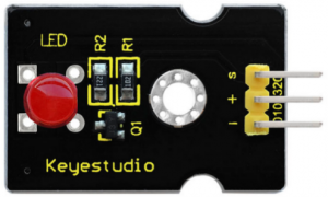
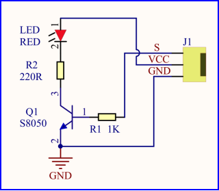
For the starter and enthusiast, this is a fundamental program---LED Blink. LED, the abbreviation of light emitting diodes, consist of Ga, As, P, N chemical compound and so on. The LED can flash diverse color by altering the delay time in the test code. When in control, power on GND and VCC, the LED will be on if S end is high level; nevertheless, it will go off.
(2)Specification
- Control interface: digital port
- Working voltage: DC 3.3-5V
- Pin spacing: 2.54mm
- LED display color: red
(3) Equipment
(4) Wiring Diagram
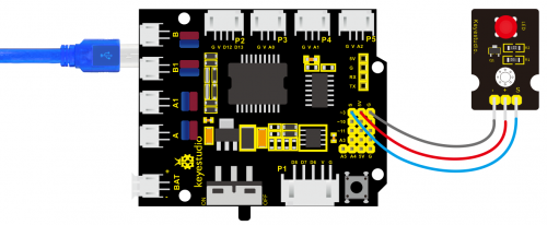
The expansion board is stacked on development board, LED module is connected to G of shield, “+”is linked with 5V, S end is attached to D3.
(5)Test Code:
/*
 keyestudio 4wd BT Car V2
 lesson 1.1
 Blink
 http://www.keyestudio.com
*/
void setup()
 {
    pinMode(3, OUTPUT);// initialize digital pin 3 as an output.
}
void loop() // the loop function runs over and over again forever
{  digitalWrite(3, HIGH); // turn the LED on (HIGH is the voltage level)
   delay(1000); // wait for a second
   digitalWrite(3, LOW); // turn the LED off by making the voltage LOW
   delay(1000); // wait for a second
}//*******************************************************************
(6)Test Result
Upload the program, LED flickers with the interval of 1s.
(7)Code Explanation
pinMode(3,OUTPUT) - This function can denote that the pin is INPUT or OUTPUT
digitalWrite(3,HIGH) - When pin is OUTPUT, we can set it to HIGH(output 5V) or LOW(output 0V)
(8) Extension Practice
We succeed to blink LED. Next, let’s observe what LED will change if we modify pins and delay time.
/*
 keyestudio 4wd BT Car V2
 lesson 1.2
 delay
 http://www.keyestudio.com
*/
void setup() {  // initialize digital pin 11 as an output.
   pinMode(3, OUTPUT);
}
// the loop function runs over and over again forever
void loop()
 { digitalWrite(3, HIGH); // turn the LED on (HIGH is the voltage level)
   delay(100); // wait for 0.1 second
   digitalWrite(3, LOW); // turn the LED off by making the voltage LOW
   delay(100); // wait for 0.1 second
}//****************************************************************
The LED flickers faster through the test result, therefore, pins and delay time affect flash frequency.
Project 2: Adjust LED Brightness
(1)Description In previous lesson, we control LED on and off and make it blink. In this project, we will control LED brightness through PWM to simulate breathing effect. Similarly, you can change the step length and delay time in the code so as to demonstrate different breathing effect. PWM is a means of controlling the analog output via digital means. Digital control is used to generate square waves with different duty cycles (a signal that constantly switches between high and low levels) to control the analog output.In general, the input voltage of port are 0V and 5V. What if the 3V is required? Or what if switch among 1V, 3V and 3.5V? We can’t change resistor constantly. For this situation, we need to control by PWM.
图


