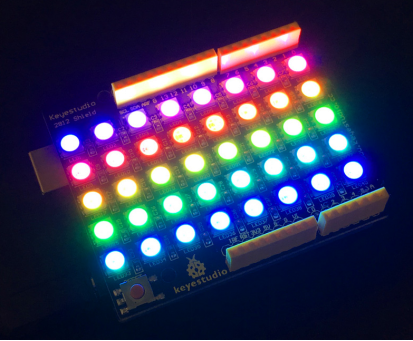
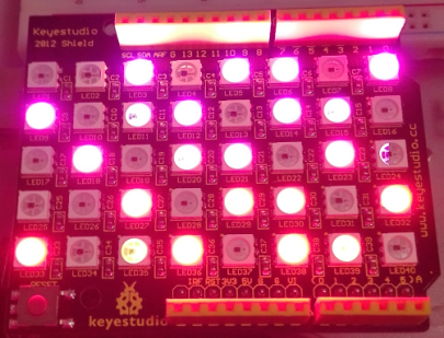
Ks0163 keyestudio 40 RGB LED 2812 Pixel Matrix Shield: Difference between revisions
Keyestudio (talk | contribs) |
Keyestudio (talk | contribs) |
||
| (15 intermediate revisions by the same user not shown) | |||
| Line 4: | Line 4: | ||
<br> | <br> | ||
==Introduction== | ==Introduction== | ||
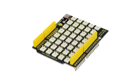
keyestudio 2812 shield adopts stackable design compatible with UNO board. It is an intelligent controlled LED light source that the control circuit and RGB chip are integrated in a 5050 SMD component. It includes intelligent digital port data latch and signal reshaping amplification drive circuit. Also includes a precision internal oscillator and a 12V programmable constant current control part, effectively ensuring the highly consistency of the pixel point light color.<br> | keyestudio 2812 shield adopts stackable design, compatible with UNO board. It is an intelligent controlled LED light source that the control circuit and RGB chip are integrated in a 5050 SMD component. It includes intelligent digital port data latch and signal reshaping amplification drive circuit. Also includes a precision internal oscillator and a 12V programmable constant current control part, effectively ensuring the highly consistency of the pixel point light color.<br> | ||
The data transfer protocol uses single NZR communication mode. After the pixel power-on reset, the DI port receives data from controller, the first pixel collect initial 24bit data then sent to the internal data latch.<br> | The data transfer protocol uses single NZR communication mode. After the pixel power-on reset, the DI port receives data from controller, the first pixel collect initial 24bit data then sent to the internal data latch.<br> | ||
LED has the advantages of low driving voltage, environmental-friendly, energy saving high brightness, large scattering angle, good consistency, long life span, etc. <br> | LED has the advantages of low driving voltage, environmental-friendly, energy saving, high brightness, large scattering angle, good consistency, long life span, etc. <br> | ||
<br> | <br> | ||
== Specification of Single LED == | == Specification of Single LED == | ||
* Anti-reverse protection circuit | * Anti-reverse protection circuit; the reverse power connection will not damage the internal IC of the LED. | ||
* IC control circuit and LED point light source | * IC control circuit and LED point light source use the same power supply. | ||
* Control circuit and the RGB chip are integrated | * Control circuit and the RGB chip are integrated into a 5050 SMD component, forming a complete control of pixel point. | ||
* Built-in signal reshaping circuit | * Built-in signal reshaping circuit; signals received will be wave-reshaped first and then output to the next driver, ensuring wave-form distortion not accumulate. | ||
* Built-in power on reset circuit and power-down reset circuit. | * Built-in power-on reset circuit and power-down reset circuit. | ||
* Each pixel of the three primary color can achieve 256 brightness display | * Each pixel of the three primary color can achieve 256 brightness display; complete full color display of 16777216 colors; scan frequency no less than 400Hz/s. | ||
* Serial cascade interface, to complete the reception and decoding of data via a signal line. | * Serial cascade interface, to complete the reception and decoding of data via a signal line. | ||
* When transmission distance between two arbitrary points is no more than five meters, no extra circuit needed. | * When transmission distance between two arbitrary points is no more than five meters, no extra circuit needed. | ||
| Line 23: | Line 24: | ||
<br> | <br> | ||
== Advantages == | == Advantages == | ||
* LED with built-in IC is brighter than common LED | * LED with built-in IC is brighter than common LED | ||
* High consistency of RGB | * High consistency of RGB chip inside all LEDs | ||
* Built-in driver IC with reliable performance. | * Built-in driver IC with reliable performance. | ||
* Use hard plastic | * Use hard plastic packaging, preventing press damage. | ||
<br> | <br> | ||
== Details == | == Details == | ||
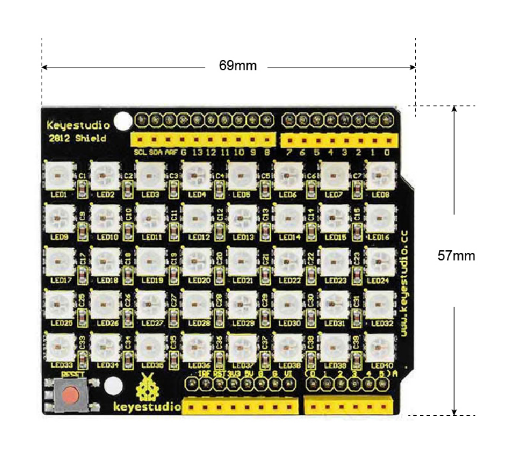
* Dimensions: 69mm x 57mm x 18mm | * '''Dimensions:''' 69mm x 57mm x 18mm | ||
* Weight: 21.1g | * '''Weight:''' 21.1g | ||
<br>[[File:Ks0163 SIZE.png|600px|frameless|thumb]]<br> | <br>[[File:Ks0163 SIZE.png|600px|frameless|thumb]]<br> | ||
<br> | |||
== PINOUTS== | |||
<br>[[File:Ks0163 pinouts.jpg|800px|frameless|thumb]]<br> | |||
<br> | |||
== Simple Hookup == | == Simple Hookup == | ||
Simply stack the shield on UNO BOARD,then connect them to your computer using a USB cable. | Simply stack the shield on [http://wiki.keyestudio.com/index.php/Ks0001_keyestudio_UNO_R3_BOARD UNO BOARD ] ,then connect them to your computer using a USB cable. | ||
<br>[[File:Hookup - ks0163.png|600px|frameless|thumb]]<br> | <br>[[File:Hookup - ks0163.png|600px|frameless|thumb]]<br> | ||
<br> | <br> | ||
==Sample Code == | ==Sample Code == | ||
* How to download and install the [http://wiki.keyestudio.com/index.php/How_to_Download_Arduino_IDE Arduino IDE ]and [http://wiki.keyestudio.com/index.php/How_to_Install_Arduino_Driver driver ]. | * How to download and install the [http://wiki.keyestudio.com/index.php/How_to_Download_Arduino_IDE Arduino IDE ]and [http://wiki.keyestudio.com/index.php/How_to_Install_Arduino_Driver driver ]. | ||
* Or [https://drive.google.com/open?id=1ngIb-HNwKNJFYybe5uu9Eto1hbsu5n9M click here to download the code ]or directly copy the code below. | * Or [https://drive.google.com/open?id=1ngIb-HNwKNJFYybe5uu9Eto1hbsu5n9M click here to download the code ]or directly copy the code below. | ||
* [https://drive.google.com/open?id=1XrXVZWfeDJ3LEzdauq8oFsSwcXSkRVRu Click here to download the libraries ] | * [https://drive.google.com/open?id=1XrXVZWfeDJ3LEzdauq8oFsSwcXSkRVRu Click here to download the libraries ] | ||
* '''Note:''' Before compile the code, do remember to add the necessary libraries inside the libraries directory of Arduino IDE. | * <span style=color:red> '''Note:''' Before compile the code, do remember to add the necessary libraries inside the libraries directory of Arduino IDE. <br> | ||
<pre> | <pre> | ||
| Line 184: | Line 196: | ||
<br> | <br> | ||
==Test Result== | ==Test Result== | ||
Done uploading the code above to the board, you should see the LED matrix blink with shiny colors. | Done uploading the code above to the board, you should see the LED matrix blink with shiny colors. | ||
[[File:图片1- ks0163.png]] | [[File:图片1- ks0163.png]] | ||
[[File:d.png]] | [[File:d.png]] | ||
| Line 197: | Line 208: | ||
==Resources == | ==Resources == | ||
''' | '''Download code and libraries :''' <br> | ||
https://fs.keyestudio.com/KS0163 | |||
''' | '''Video:''' http://video.keyestudio.com/KS0163/ | ||
<br> | <br> | ||
==Get One Now == | ==Get One Now == | ||
*[https://www.keyestudio.com/new-keyestudio-40-rgb-led-ws2812-pixel-matrix-shield-for-arduino-p0141.html '''Official Website'''] | |||
'''Shop on Amazon:''' <br> | *'''Shop on Amazon:''' <br> | ||
https://www.amazon.com/Keyestudio-Pixel-Matrix-Shield-Arduino/dp/B01E8LZD58/ | https://www.amazon.com/Keyestudio-Pixel-Matrix-Shield-Arduino/dp/B01E8LZD58/ | ||
*[https://www.aliexpress.com/store/product/NEW-Keyestudio-40-RGB-LED-WS2812-Pixel-Matrix-Shield-for-Arduino/1452162_32656163025.html?spm=2114.12010612.8148356.4.7f7e276flSHIqA '''Shop on Aliexpress''' ] | |||
[[Category: Shield]] | [[Category: Shield]] | ||
Latest revision as of 14:46, 6 January 2021
Introduction
keyestudio 2812 shield adopts stackable design, compatible with UNO board. It is an intelligent controlled LED light source that the control circuit and RGB chip are integrated in a 5050 SMD component. It includes intelligent digital port data latch and signal reshaping amplification drive circuit. Also includes a precision internal oscillator and a 12V programmable constant current control part, effectively ensuring the highly consistency of the pixel point light color.
The data transfer protocol uses single NZR communication mode. After the pixel power-on reset, the DI port receives data from controller, the first pixel collect initial 24bit data then sent to the internal data latch.
LED has the advantages of low driving voltage, environmental-friendly, energy saving, high brightness, large scattering angle, good consistency, long life span, etc.
Specification of Single LED
- Anti-reverse protection circuit; the reverse power connection will not damage the internal IC of the LED.
- IC control circuit and LED point light source use the same power supply.
- Control circuit and the RGB chip are integrated into a 5050 SMD component, forming a complete control of pixel point.
- Built-in signal reshaping circuit; signals received will be wave-reshaped first and then output to the next driver, ensuring wave-form distortion not accumulate.
- Built-in power-on reset circuit and power-down reset circuit.
- Each pixel of the three primary color can achieve 256 brightness display; complete full color display of 16777216 colors; scan frequency no less than 400Hz/s.
- Serial cascade interface, to complete the reception and decoding of data via a signal line.
- When transmission distance between two arbitrary points is no more than five meters, no extra circuit needed.
- When the refresh rate is 30fps, cascade number no less than 1024 points.
- Data sending speed can reach 800Kbps.
- The color of the light is highly consistent, cost-effective.
Advantages
- LED with built-in IC is brighter than common LED
- High consistency of RGB chip inside all LEDs
- Built-in driver IC with reliable performance.
- Use hard plastic packaging, preventing press damage.
Details
- Dimensions: 69mm x 57mm x 18mm
- Weight: 21.1g
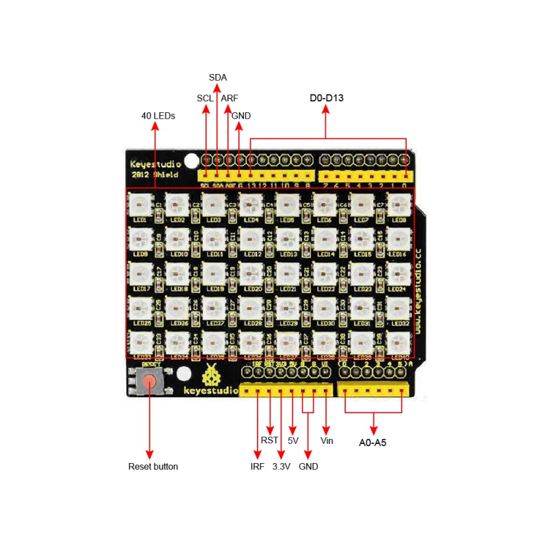
PINOUTS
Simple Hookup
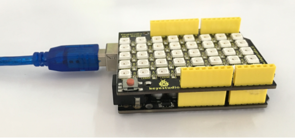
Simply stack the shield on UNO BOARD ,then connect them to your computer using a USB cable.
Sample Code
- How to download and install the Arduino IDE and driver .
- Or click here to download the code or directly copy the code below.
- Click here to download the libraries
- Note: Before compile the code, do remember to add the necessary libraries inside the libraries directory of Arduino IDE.
#include <Adafruit_NeoPixel.h>
#ifdef __AVR__
#include <avr/power.h>
#endif

#define PIN 13

// Parameter 1 = number of pixels in strip
// Parameter 2 = Arduino pin number (most are valid)
// Parameter 3 = pixel type flags, add together as needed:
//   NEO_KHZ800  800 KHz bitstream (most NeoPixel products w/WS2812 LEDs)
//   NEO_KHZ400  400 KHz (classic 'v1' (not v2) FLORA pixels, WS2811 drivers)
//   NEO_GRB     Pixels are wired for GRB bitstream (most NeoPixel products)
//   NEO_RGB     Pixels are wired for RGB bitstream (v1 FLORA pixels, not v2)
Adafruit_NeoPixel strip = Adafruit_NeoPixel(40, PIN, NEO_GRB + NEO_KHZ800);

// IMPORTANT: To reduce NeoPixel burnout risk, add 1000 uF capacitor across
// pixel power leads, add 300 - 500 Ohm resistor on first pixel's data input
// and minimize distance between Arduino and first pixel.  Avoid connecting
// on a live circuit...if you must, connect GND first.

void setup() {
  // This is for Trinket 5V 16MHz, you can remove these three lines if you are not using a Trinket
  #if defined (__AVR_ATtiny85__)
    if (F_CPU == 16000000) clock_prescale_set(clock_div_1);
  #endif
  // End of trinket special code


  strip.begin();
  strip.show(); // Initialize all pixels to 'off'
}

void loop() {
  // Some example procedures showing how to display to the pixels:
  colorWipe(strip.Color(255, 0, 0), 50); // Red
  colorWipe(strip.Color(0, 255, 0), 50); // Green
  colorWipe(strip.Color(0, 0, 255), 50); // Blue
  // Send a theater pixel chase in...
  theaterChase(strip.Color(127, 127, 127), 50); // White
  theaterChase(strip.Color(127, 0, 0), 50); // Red
  theaterChase(strip.Color(0, 0, 127), 50); // Blue

  rainbow(20);
  rainbowCycle(20);
  theaterChaseRainbow(50);
}

// Fill the dots one after the other with a color
void colorWipe(uint32_t c, uint8_t wait) {
  for(uint16_t i=0; i<strip.numPixels(); i++) {
    strip.setPixelColor(i, c);
    strip.show();
    delay(wait);
  }
}

void rainbow(uint8_t wait) {
  uint16_t i, j;

  for(j=0; j<256; j++) {
    for(i=0; i<strip.numPixels(); i++) {
      strip.setPixelColor(i, Wheel((i+j) & 255));
    }
    strip.show();
    delay(wait);
  }
}

// Slightly different, this makes the rainbow equally distributed throughout
void rainbowCycle(uint8_t wait) {
  uint16_t i, j;

  for(j=0; j<256*5; j++) { // 5 cycles of all colors on wheel
    for(i=0; i< strip.numPixels(); i++) {
      strip.setPixelColor(i, Wheel(((i * 256 / strip.numPixels()) + j) & 255));
    }
    strip.show();
    delay(wait);
  }
}

//Theatre-style crawling lights.
void theaterChase(uint32_t c, uint8_t wait) {
  for (int j=0; j<10; j++) {  //do 10 cycles of chasing
    for (int q=0; q < 3; q++) {
      for (int i=0; i < strip.numPixels(); i=i+3) {
        strip.setPixelColor(i+q, c);    //turn every third pixel on
      }
      strip.show();

      delay(wait);

      for (int i=0; i < strip.numPixels(); i=i+3) {
        strip.setPixelColor(i+q, 0);        //turn every third pixel off
      }
    }
  }
}

//Theatre-style crawling lights with rainbow effect
void theaterChaseRainbow(uint8_t wait) {
  for (int j=0; j < 256; j++) {     // cycle all 256 colors in the wheel
    for (int q=0; q < 3; q++) {
      for (int i=0; i < strip.numPixels(); i=i+3) {
        strip.setPixelColor(i+q, Wheel( (i+j) % 255));    //turn every third pixel on
      }
      strip.show();

      delay(wait);

      for (int i=0; i < strip.numPixels(); i=i+3) {
        strip.setPixelColor(i+q, 0);        //turn every third pixel off
      }
    }
  }
}

// Input a value 0 to 255 to get a color value.
// The colours are a transition r - g - b - back to r.
uint32_t Wheel(byte WheelPos) {
  WheelPos = 255 - WheelPos;
  if(WheelPos < 85) {
    return strip.Color(255 - WheelPos * 3, 0, WheelPos * 3);
  }
  if(WheelPos < 170) {
    WheelPos -= 85;
    return strip.Color(0, WheelPos * 3, 255 - WheelPos * 3);
  }
  WheelPos -= 170;
  return strip.Color(WheelPos * 3, 255 - WheelPos * 3, 0);
}
Test Result
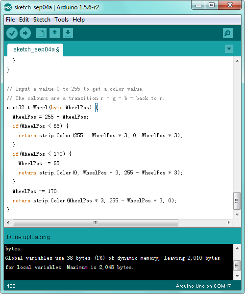
Done uploading the code above to the board, you should see the LED matrix blink with shiny colors.
Resources
Download code and libraries :
https://fs.keyestudio.com/KS0163
Video: http://video.keyestudio.com/KS0163/
Get One Now
- Shop on Amazon:
https://www.amazon.com/Keyestudio-Pixel-Matrix-Shield-Arduino/dp/B01E8LZD58/
