Mixly Projects
Getting Started with Hardware Projects
Project 1: Built-in LED
When it comes to using the REV4 as core of our robot, the REV4 is the best board to get started with electronics and coding.
If this is your first experience tinkering with the platform, the REV4 is the most robust board you can start playing with.
Well, let's at first have a look at this.
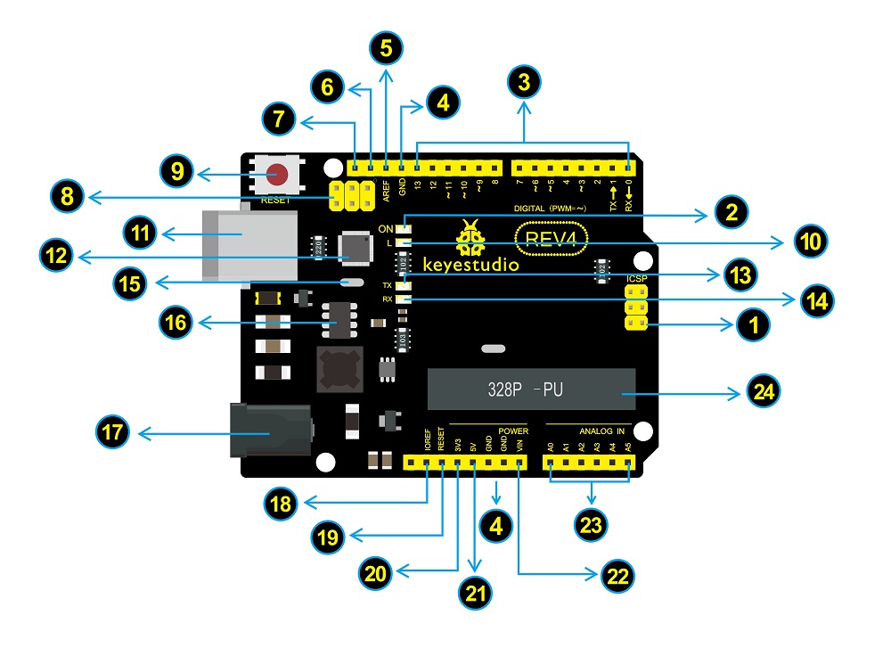
Here is an explanation chart of what every element and interface of the board does:

|
ICSP (In-Circuit Serial Programming) Header
In most case, ICSP is the AVR,an Arduino micro-program header consisting of MOSI, MISO, SCK, RESET, VCC, and GND. It is often called the SPI (serial peripheral interface) and can be considered an "extension" of the output. In fact, slave the output devices under the SPI bus host. |

|
Power LED Indicator
Powering the Arduino, LED on means that your circuit board is correctly powered on. If LED is off, connection is wrong. |

|
Digital I/O
Arduino REV4 has 14 digital input/output pins (of which 6 can be used as PWM outputs). These pins can be configured as digital input pin to read the logic value (0 or 1). Or used as digital output pin to drive different modules like LED, relay, etc. The pin labeled “〜” can be used to generate PWM. |

|
GND ( Ground pin headers)
Used for circuit ground |

|
AREF
Reference voltage (0-5V) for analog inputs. Used with analogReference(). |

|
SDA
IIC communication pin |

|
SCL
IIC communication pin |

|
ICSP (In-Circuit Serial Programming) Header
In most case, ICSP is the AVR,an Arduino micro-program header consisting of MOSI, MISO, SCK, RESET, VCC, and GND. Connected to ATMEGA 16U2-MU. When connecting to PC, program the firmware to ATMEGA 16U2-MU. |

|
RESET Button
You can reset your Arduino board, for example, start the program from the initial status. You can use the RESET button. |

|
D13 LED
There is a built-in LED driven by digital pin 13. When the pin is HIGH value, the LED is on, when the pin is LOW, it's off. |

|
USB Connection
Arduino board can be powered via USB connector. All you needed to do is connecting the USB port to PC using a USB cable. |

|
ATMEGA 16U2-MU
USB to serial chip, can convert the USB signal into serial port signal. |

|
TX LED
Onboard you can find the label: TX (transmit) When Arduino board communicates via serial port, send the message, TX led flashes. |

|
RX LED
Onboard you can find the label: RX(receive ) When Arduino board communicates via serial port, receive the message, RX led flashes. |

|
Crystal Oscillator
Helping Arduino deal with time problems. How does Arduino calculate time? by using a crystal oscillator. |

|
Voltage Regulator
To control the voltage provided to the Arduino board, as well as to stabilize the DC voltage used by the processor and other components. |

|
DC Power Jack
Arduino board can be supplied with an external power DC7-12V from the DC power jack. |

|
IOREF
Used to configure the operating voltage of microcontrollers. Use it less. |

|
RESET Header
Connect an external button to reset the board. The function is the same as reset button (labeled 9) |

|
Power Pin 3V3
A 3.3 volt supply generated by the on-board regulator. Maximum current draw is 50 mA. |

|
Power Pin 5V
Provides 5V output voltage |

|
Vin
You can supply an external power input DC7-12V through this pin to Arduino board. |

|
Analog Pins
Arduino REV4 board has 6 analog inputs, labeled A0 through A5. |

|
Microcontroller
Each Arduino board has its own microcontroller. You can regard it as the brain of your board. |
Let’s make a simple test for the REV4 built-in LED (D13).
We will work on blinking an LED. That’s right - it’s as simple as turning a light on and off!
Now enough talking - let’s get started with the LED project.
Blinking an LED
It’s pretty simple to turn a built-in led on and off. We only require REV4 control board and a USB cable to enter the wonderful programming world.
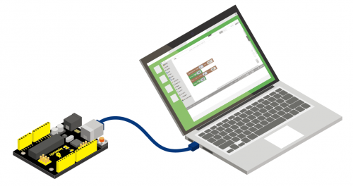
Connect your REV4 board to the computer’s USB port using a USB cable for communication.
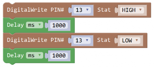
Test Code:
Open Mixly blocks platform to get started with coding.
First, click IN/OUT, drag the “DigitalWrite PIN# (0)Stat(HIGH)” block.

This block is used to set the level HIGH or LOW of Digital pin.
- Select HIGH is to set the HIGH level.
- Select LOW is to set the LOW level.
- The HIGH level is the state of high voltage, generally recorded as 1.
- High voltage, high current, the LED lights.
- The LOW level is the state of low voltage, generally recorded as 0.
- Low voltage, low current, the LED Not lights.
To observe the LED blink obviously, we need to add a Delay block.
Check the test code below and upload it to your REV4 board.
What you should see:
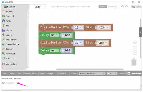
Drag the test code to Mixly window; remember to select the proper board and COM port.
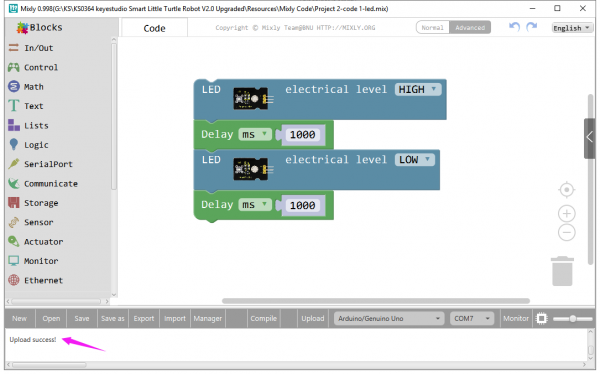
Then compile and upload the code to your control board. Upload success message will appear on the bottom bar.
The REV4 built-in LED (label “L”) will turn on for 1 second, and then turn off for 1 second, alternately and circularly.
File:File:KS0341 sy.jpg
Project 2: Light up an LED
In this course, we create 2 test codes. One for turning LED on and off, blinking effect; the other is to change the brightness of LED using the step and delay function in the code, simulating the breath effect.
Overview:
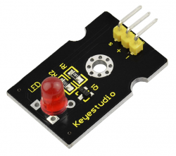
This is keyestudio red LED module. On the module, you will see a light emitting diode (LED), which has two states ON and OFF.
The LED module leads out three pins of 2.54mm pitch, respectively negative pin (marked -), positive pin (marked +) and signal pin (marked S).
The - pin is connected to ground, + pin is connected to VCC(3.3-5V), S pin is for signal control; you can set the High or Low level to control the LED on and off.
After programming, it will emit red light color. You can combine with other sensors to do various interactive experiments.
You can choose other LED modules to emit different light colors like blue, green, yellow and white.
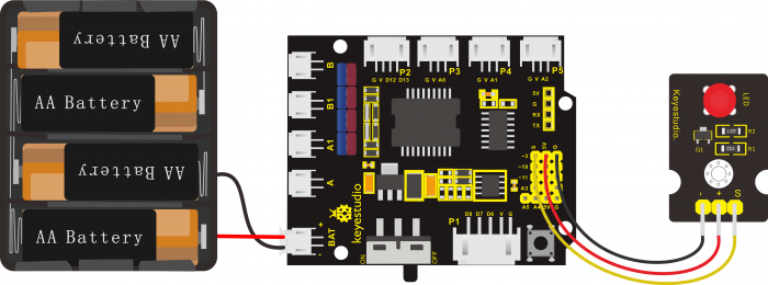
Wiring Diagram:
Note: stack the motor drive shield on the REV4 board; connect red LED module to motor drive shield (pin - for GND, + for 5V, S for digital pin3 (S)). Connect the power to BAT connector.
Coding:
Now write the program to make the red LED flash.
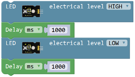
Go to “Small_Turtle_Robot” , drag out the block![]() , this block is used to set the HIGH/LOW for digital port;
, this block is used to set the HIGH/LOW for digital port;
Click the drop-drown triangle icon to select HIGH for digital pin, with voltage; select LOW for digital pin, with no voltage.
So what should we set the red LED pin output HIGH or LOW to turn on the LED? Through testing, set to HIGH, red LED turns on; set to LOW, red LED turns off.
Go to “Control” , drag out the block![]() ;
;
Duplicate this piece of code string  once and set to LOW.
We turn on the red LED for one second then off for one second.
Code 2:
The Arduino controller has 12 common digital pins (digital pin 2-13); the general digital pins can only output HIGH or LOW level.
The pin labeled “〜” is also called PWM (“Pulse-Width Modulation”) pins. The Arduino controller has totally 6 PWM outputs, which are Digital 3, 5, 6, 9, 10 and 11). The PWM pins can steadily output the HIGH and LOW level, and can continuously change HIGH or LOW in a regular time period.
The effect of LED gradually brightening and darkening is controlled by PWM. The PWM can control 0-255 "level" of voltage output.
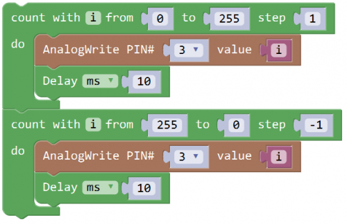
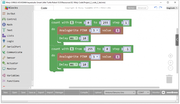
Go to “Control” , drag out block![]() ; here can set any random number. i is a variable. Red LED brighter is the Level variable increasing from 0 to 255. So we first set the variable i from 0 to 255 step 1.
; here can set any random number. i is a variable. Red LED brighter is the Level variable increasing from 0 to 255. So we first set the variable i from 0 to 255 step 1.
Go to “IN/OUT” , drag the ![]() block into the step block just made. Select pin 3 and drag a variables block
block into the step block just made. Select pin 3 and drag a variables block ![]() from “Variables” into the value. And add a Delay block and set to 10ms.
from “Variables” into the value. And add a Delay block and set to 10ms.
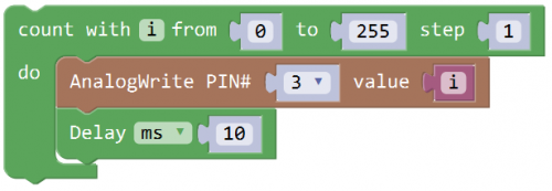
This piece of code block means the red LED is gradually brightening per 10 milliseconds with a step of 1.
What about the LED dimming? the red LED darkening is the Level variable increasing from 255 to 0.
We duplicate the above code once; set as i from 255 to 0 step -1.
Upload the complete code to see the result.
What you will see
Drag the test code 1 to Mixly window, compile the code and then click on the 'Upload' button.
You will see the message “Upload success” appear on the bottom bar.
Turn the slide switch to ON position.
Eventually, the LED lights up for one second, then off one second, circularly.
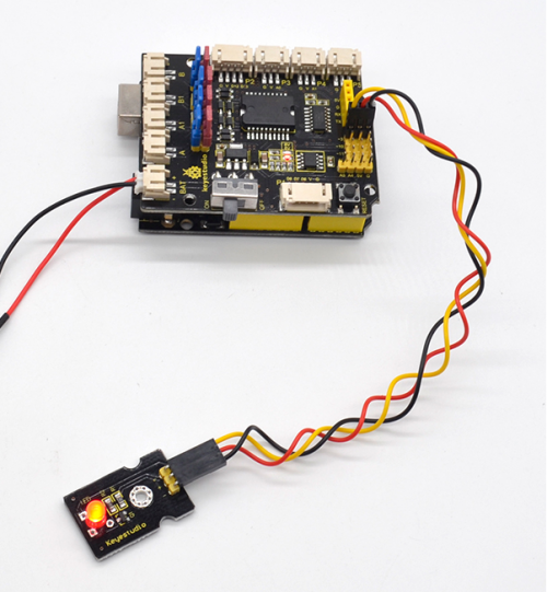
Upload Code 2 to the REV4 board; turn the slide switch to ON position.
The LED will simulate the human breath, gradually brightening and then gradually dimming, alternatively and circularly.
- Little Knowledge:
1. In the code 1, we’ve set the signal pin of LED module to D3 in the library. Or be able to randomly set the LED signal pin without library.
using the block
 ![]() also makes sense.
also makes sense.
2.What happens when you change the number in one or both of the delay(1000):
This delay period is in milliseconds, so if you want the LED display as low or fast, change the value, try 2000 or 500.
3.In the code 2, we use the block ![]()
The LED signal pin is connected to D3; set the PWM value to 0. The PWM value is in the range of 0-255. The greater the value set, the brighter the LED is.
4. means the variable i increases direct from 0 to 255; each step plus 1.
 means the variable i direct reduces direct from 255 to 0; each step minus 1.
- Extension Practice:
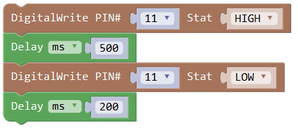
1.Set the LED blink without using library; set the signal pin of LED to D11; turn on for 0.5 second, then off for 0.2 second, alternately and circularly.
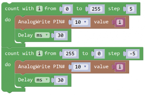
2.Change the Code 2. Set the LED signal pin connect to D10;
When gradually brightening: PWM value increases from 0 to 255; each step plus 5; delay 30ms.
When gradually dimming: PWM value reduces from 255 to 0; each step minus 5; delay 50ms.
Project 3: Light up LED Matrix
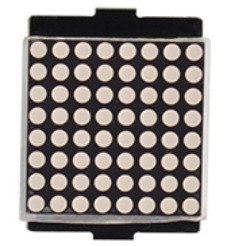
In the previous project, we have simply tested the LED. We now have added a new 8*8 Dot Matrix module to the turtle robot to show the moving states. Amazing display!
Do you know how is the cool advertising display made? It is exactly composed of these small LED matrix. If you want to make a similar display, this keyestudio 8*8 Dot Matrix module will meet you need.
Overview:
This tiny display has 64 LEDs packed into a 8*8 dot matrix. It integrated HT16K33 as driver chip, so with this LED matrix module, you can control it through connecting I2C communication interfaces ( A4-SDA ; A5-SCL).
It is great for displaying image/text or creating bizarre patterns, and is highly portable and convenient to use. Of course you can program it via IDE or via Mixly block. With just a few steps, you are ready to impress others!
Wiring Diagram:
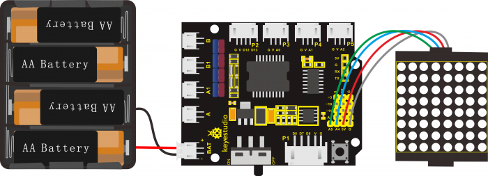
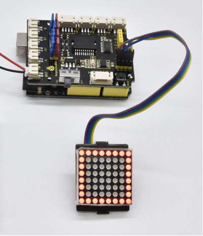
Note: stack the motor drive shield on the REV4 board; connect LED matrix module to motor drive shield (pin G for GND, V for 5V, SDA for A4, SCL for A5). Connect the power to BAT connector.
Coding:
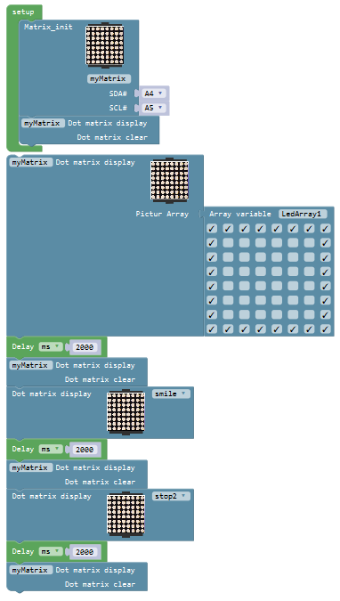
Now write the program to make the LED matrix display patterns. We first set the pins then design and display the pattern.
Click “Small_Turtle_Robot” , drag out the block ; here default SDA pin to A4, SCL pin to A5. To clear the display patterns set before, need to clear the screen.
Go to “Control” , drag out block , and drag the block
 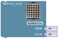 into setup block. And again drag the block
 ![]() beneath the block just made.
beneath the block just made.
Next design and display the pattern, need to call the block 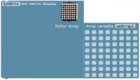 and
and  .
.
For instance, tick the ledArray to show the icon you want. When tick the ledArray, it will appear the mark “√”, that is, lit the corresponding led.
Here we draw a large square pattern.
Go to “Control” , drag out block![]() , set to delay 2000ms. And go to “Small_Turtle_Robot” , drag out the block
, set to delay 2000ms. And go to “Small_Turtle_Robot” , drag out the block ![]() beneath the delay block. And again drag out the block
beneath the delay block. And again drag out the block , click the drop-down triangle to select other patterns.

Then add a delay block 2000ms and a display clear block.
And duplicate the piece of code string once; click the drop-down triangle to select pattern stop2.
Upload the finished code to see the display effect!
What you will see:
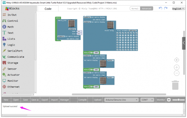
Drag the test code to Mixly window, compile the code and then click on the 'Upload' button. You will see the message “Upload success” appear on the bottom bar.
Turn the slide switch to ON position.
You should see the keyestudio 8*8 Dot matrix show the square icon for 2 seconds, a smile face icon for 2 seconds, stop displaying for 2 seconds, alternately and circularly.
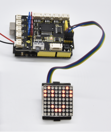
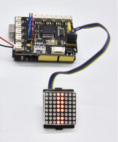
- Little Knowledge:
1.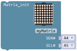 In the code, we are able to set the I2C communication pin and connect to the proper pin.
2. Means clear the patterns shown on the dot matrix screen.
3.You can define the pattern you want to display; no need to set by yourself; just direct call the patterns in the library.
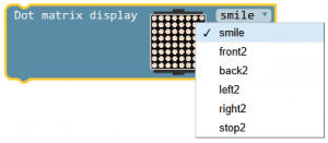
4.In the code, we can also set any patterns as we like; just tick in the dot matrix, indicating that the point is lit.
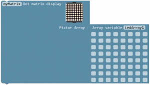
Set the first pattern as![]() ; the second pattern should be LedArray2; And so on...
; the second pattern should be LedArray2; And so on...
- Extension Practice:
1.Set a static icon you like and show on the dot matrix;
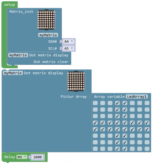
2.Set a dynamic icon you want to show on the dot matrix.

Project 4: Line Tracking Sensor
Overview:
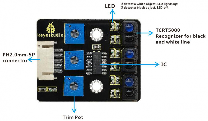
The tracking sensor is actually an infrared sensor. The component used here is the TCRT5000 infrared tube. Its working principle is to use the different reflectivity of infrared light to the color, then convert the strength of the reflected signal into a current signal.
During the process of detection, black is active at HIGH level, but white is active at LOW. The detection height is 0-3 cm.
For keyestudio 3-channel line tracking module, we have integrated 3 sets of TCRT5000 infrared tube on a single board. It is more convenient for wiring and control.
By rotating the adjustable potentiometer on the sensor, it can adjust the detection sensitivity of the sensor.
Special note: before testing, turn the potentiometer on the sensor to adjust the detection sensitivity.
When adjust the LED front the trimpot at the threshold between ON and OFF, the sensitivity is the best.
TECH SPECS:
- Operating Voltage: 3.3-5V (DC)
- Interface: 5PIN
- Output Signal: Digital signal
- Detection Height: 0-3 cm
Wiring Diagram:
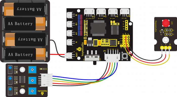
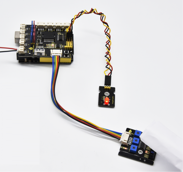
Note: stack the motor drive shield onto REV4 control board. connect the line tracking sensor to motor drive shield’s P1 connector (G, V, D6, D7, D8);
Connect the pin (-、+、S) of red LED module to the pin G, 5V, D3(S) of motor drive shield with 3P female-to-female jumper wire; connect the power supply to BAT connector.
Coding:
Now write the program to test the line tracking sensor.
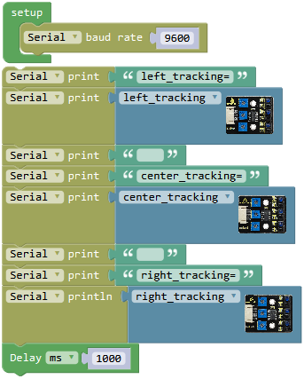
Go to “Control”, drag out the “setup” block; and drag the “Serial baud rate(9600)”block from “SerialPort” into the “setup” block.
To respectively read the left, the center and the right tracking sensor on the line tracking module, we click the “SerialPort” , drag out the block![]() ; drag out the block
; drag out the block![]() from “Text” into the block
from “Text” into the block ![]() , and then duplicate the complete block six times. Change the first
, and then duplicate the complete block six times. Change the first![]() to “left_tracking=”; drag out the block
to “left_tracking=”; drag out the block  from library “Desktop_Car_V3” to replace the second
 ![]() ; delete the third hello box, forming a blank box; change the fourth
; delete the third hello box, forming a blank box; change the fourth ![]() to
to
“center_tracking=”.
Duplicate the block once to replace the fifth
![]() and click the drop-down triangle icon to select the “center_tracking”; delete the sixth hello box, forming a blank box; change the seventh
and click the drop-down triangle icon to select the “center_tracking”; delete the sixth hello box, forming a blank box; change the seventh ![]() to “right_tracking=”.
to “right_tracking=”.
And again go to “SerialPort”, drag out the block ![]() ; duplicate the block
; duplicate the block  once and drag it into
 ![]() , click the drop-down triangle icon to select the “right_tracking”
And go to “Control”, drag the delay block
, click the drop-down triangle icon to select the “right_tracking”
And go to “Control”, drag the delay block![]() ; set to delay 1000ms.
; set to delay 1000ms.
Complete and upload the above code to see the result. It can tell black and white.
Through testing, if line tracking sensor detects white, output LOW 0 and the built-in LED turns on red; detecting black, output HIGH 1 and the built-in LED is off.
We’ve measured what signal the line tracking sensor sends. Next the white LED is turned on when any tracking sensor detects white.
Next write the program that can turn on or off white LED module using line tracking sensor.
To judge whether the left, the center and the right tracking sensor detect black or white, here we can use the condition statement  or
or  .
.
But the block is more efficient than
 .
.
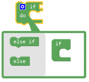
Go to “Control”, drag out the block , then click the blue gear icon, appear the edit box, drag the block
 ![]() into
into  block. So you can get the block
 .
.
Next, go to the “Logic”, drag out the block![]() , and drag out the block
, and drag out the block from the “Desktop_Car_V3” into the first input box at the left side of “=”;
drag the ![]() from the “Math” into the second input box at the right side of “=” ; like this:
from the “Math” into the second input box at the right side of “=” ; like this: .
.
We duplicate the block twice, and respectively click the drop-down triangle icon to select “center_tracking” and “right_tracking”.
 .
.
And again go to the “Logic”, drag out the block![]() and click the drop-down triangle to select “or”; duplicate the block
and click the drop-down triangle to select “or”; duplicate the block ![]() once and make as
once and make as ![]() ; drag this block behind into the if statement.
; drag this block behind into the if statement.
Now respectively drag the block ,
, and
and into the input box of block
![]() .
.
Click the “Desktop_Car_V3”, drag out the block![]() into do statement, keep HIGH; duplicate the block once and set to LOW and drag it into else statement.
into do statement, keep HIGH; duplicate the block once and set to LOW and drag it into else statement.

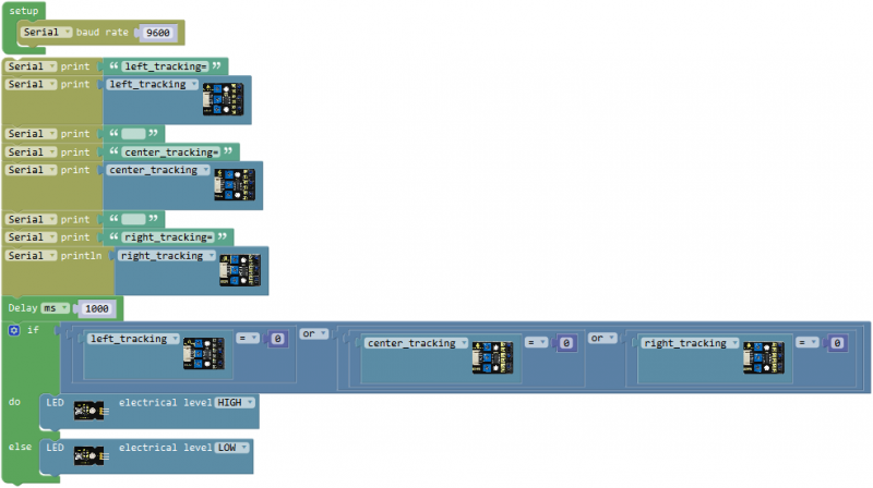
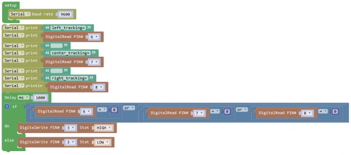
Now we have written the code of tracking sensor controlling white LED module. Upload the complete to see the final result!
Result:
Drag the test code to Mixly window, compile the code and then click on the 'Upload' button.
You will see the message “Upload success” appear on the bottom bar. Turn the slide switch to ON position.
When any TCRT5000 infrared pair transistor on the line tracking sensor detects white, LED module will turn on; otherwise, LED turns off.
- Little Knowledge:
1.In the code, we use the library  to read the HIGH/LOW of the left sensor (D6); using the block
  also makes sense.
The signal pin of the middle sensor is D7; the signal pin of the right sensor is D8.
2.![]() means the baud rate is set to 9600;
means the baud rate is set to 9600;
![]() Print the specified number, text or other value on serial monitor.
Print the specified number, text or other value on serial monitor.
![]() Print the specified number, text or other value on newline of monitor.
Print the specified number, text or other value on newline of monitor.
3.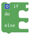 means that if condition 1 is satisfied, it's going to be A, otherwise it's going to be B.
When using, you can find the if...do...statement block in the Mixly Control Block. Then click the gear icon on the block to drag out the else or else if block you need to use.
4.![]() This is a logical statement. It’s available as long as can satisfy any one of the three conditions.
This is a logical statement. It’s available as long as can satisfy any one of the three conditions.
- Extension Practice:
1.Try to change the code without using library to make the same result.
Project 5: Ultrasonic Detecting Obstacles
Overview:
The ultrasonic module will emit the ultrasonic waves after trigger signal. When the ultrasonic waves encounter the object and are reflected back, the module outputs an echo signal, so it can determine the distance of object from the time difference between trigger signal and echo signal.
We can use the ultrasonic sensor to detect whether there is an obstacle ahead. It is commonly used to measure the distance between the front obstacle and robot.
In the process of robot DIY, we can use the measured distance by ultrasonic sensor to build functional robots, such as automatic avoiding, following, etc.
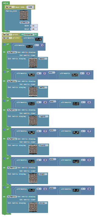
In the experiment, we use the ultrasonic sensor to measure the distance between the robot and front obstacle, controlling the LED matrix show the images.
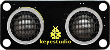
TECH SPECS:
- Operating Voltage: DC 5V
- Operating Current: 15mA
- Operating Frequency: 40khz
- Maximum Range: 2-3m
- Minimum Range: 2m
- Sensing Angle: 15 degrees
- Trigger Input Signal: 10µS TTL pulse
Wiring Diagram:
Note: stack the motor drive shield onto REV4 control board. Connect the ultrasonic sensor to motor drive shield’s P2 connector, VCC pin to V, Trig pin to digital 13 (S), Echo pin to digital 12 (S), G pin to GND(G);
Connect the pin G、V、SDA、SCL of dot matrix module to the pin G、5V、A4、A5 of motor drive shield with female-to-female jumper wire.
Connect the power supply to BAT connector.
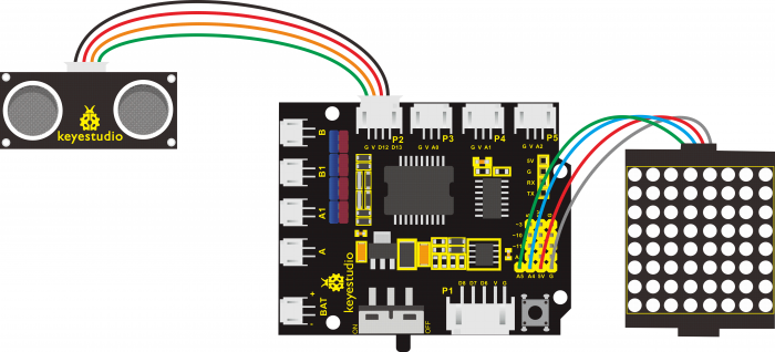
Coding:
The ultrasonic sensor is connected to P2 connector of motor drive shield , VCC pin to V, Trig pin to digital 13 (S), Echo pin to digital 12 (S), G pin to GND(G); Trig pin is to trigger signal and Echo pin is to receive echo signal.
Next need to write the program to get the specific distance measured by ultrasonic sensor.
Go to “Control” , drag out the “setup” block ![]() ;
;
Drag out the block ![]() from “SerialPort” into the “setup” block.
from “SerialPort” into the “setup” block.
Go to the “SerialPort” again, drag out the block![]() and
and ![]()
Go to “Text”, drag out the block  into the block
 ![]() , and change the word “hello” to “distance=”.
, and change the word “hello” to “distance=”.
Then go to “Small_Turtle_Robot”, drag and drop the ultrasonic block  into “Serial printIn” block;
To make the value print slowly, we add a delay block.
And again go to “Control”, drag the delay block ; set the delay time in 100ms.
Upload the code success, open the serial monitor to check the distance between ultrasonic sensor and an obstacle.
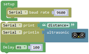
In the following, try to realize another two distance situations:
When the measured distance between the ultrasonic sensor and front obstacles is smaller than 10cm, dot matrix display a smile face pattern.
When the measured distance between the ultrasonic sensor and front obstacles is greater than 10cm, clear the dot matrix display.
To judge whether the distance is smaller than 10cm or greater than 10cm, here we can use the condition statement ![]() or
or  . But the block
  is more efficient than
 ![]() .
.
Go to “Control”, drag out the block![]() , then click the blue gear icon, appear the edit box, drag the
, then click the blue gear icon, appear the edit box, drag the ![]() block into
block into  block. So you can get the block
  .
.
Next, go to “Logic”, drag the block ![]() into the if statement, and drag out the block
into the if statement, and drag out the block ![]() from the “Small_Turtle_Robot” into the first input box at the left side of “=”; drag the
from the “Small_Turtle_Robot” into the first input box at the left side of “=”; drag the ![]() from the “Math” into the second input box at the right side of “=” ; change the“=” to“<” , change the value 0 to 10; like this:
from the “Math” into the second input box at the right side of “=” ; change the“=” to“<” , change the value 0 to 10; like this:![]() .
.
First set up the dot matrix display, click “Small_Turtle_Robot”, drag out the block 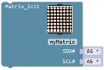 into the setup block; here default SDA pin to A4, SCL pin to A5. And again drag out the block
  into the do statement, click the drop-down triangle to select smile pattern. The dot matrix will display a smile pattern. And drag out the block
 ![]() into the else statement.
into the else statement.
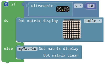
Now we have written the test code for ultrasonic sensor. Upload the code and move an obstacle in front of ultrasonic sensor to check the result.
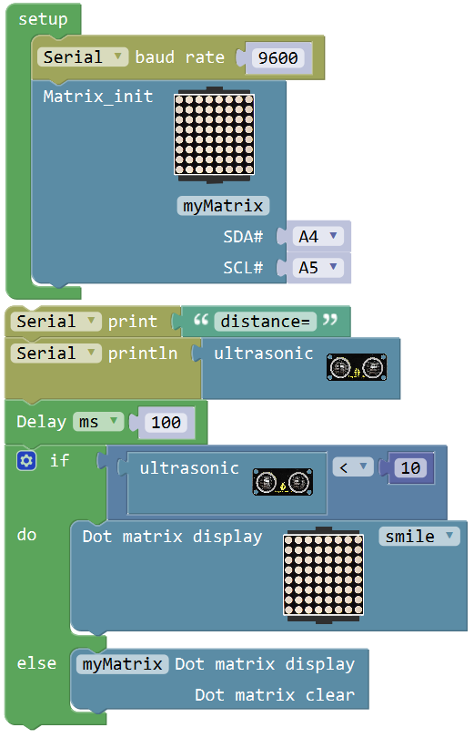
What you will see
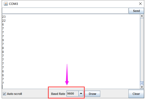
Upload the code success, open the monitor and set the baud rate to 9600. Turn the Slide switch ON.
When place an obstacle in front of the ultrasonic sensor, the measured distance between an obstacle and sensor is showed on the monitor. The unit is cm.
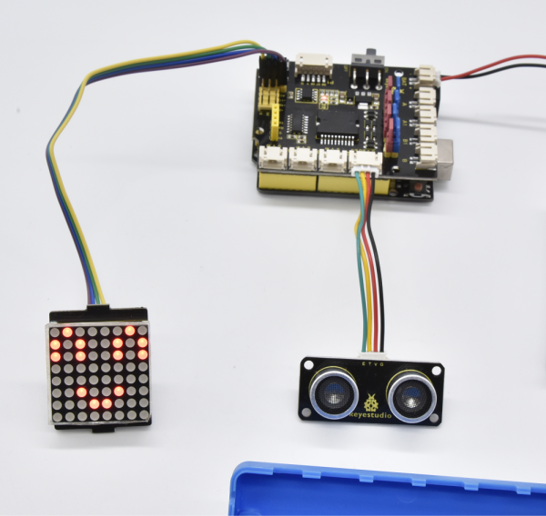
When the measured distance is less than 10cm, LED matrix shows a smile image; otherwise, no image display.
- Little Knowledge:
1.In the code, we use the  to measure the distance between ultrasonic sensor and obstacle ahead, with a unit of cm.
2.![]() : print the distance value on the newline of monitor. The baud rate default by 9600.
: print the distance value on the newline of monitor. The baud rate default by 9600.
If use the block ![]() , it will not print the value on the newline; just print on the monitor. The difference between them is whether need to make line wrap.
, it will not print the value on the newline; just print on the monitor. The difference between them is whether need to make line wrap.
3.What happens when you change the number in one or both of the delay(1000)

This delay period is in milliseconds, so if you want the LED to blink as low or fast, change the value, try 500 or 2000.
4. means that if condition 1 is satisfied, it's going to be A, otherwise it's going to be B.
When using, you can find the if...do...statement block in the Mixly Control Block. Then click the gear icon on the block to drag out the else or else if block you need to use.

- Extension Practice:
1.Change the distance value measured by ultrasonic sensor to make the LED panel show different patterns.
Project 6: Infrared Receiver
- IR Remote Control:
There is no doubt that infrared remote control is commonly seen in our daily life. It's hard to imagine our world without it.
An infrared remote control can be used to control a wide range of home appliances such as television, audio, video recorders and satellite signal receivers.
Well, in the following let’s get a better understanding of the infrared remote control.
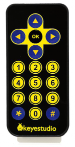
Infrared remote control is composed of infrared transmitting and infrared receiving systems. That is, consist of an infrared remote control, an infrared receiver module and a microcontroller that can decode. You can refer to the figure below.

The 38K infrared carrier signal transmitted by an infrared remote controller is encoded by an encoding chip inside the remote controller. It is composed of a pilot code, user code, data code, and data inversion code.
The time interval between pulses is used to distinguish whether it is a signal 0 or 1. (when the ratio of high level to low level is about 1:1, considered as signal 0.) And the encoding is just well composed of signal 0 and 1.
The user code of the same button on remote controller is unchanged. Using difference data distinguish the key pressed on the remote control.
When press down a button on the remote control, it will send out an infrared carrier signal. And when infrared receiver receives that signal, its program will decode the carrier signal, and through different data codes, thus can judge which key is pressed.
The microcontroller is decoded by an received signal 0 or 1 to determine which key is pressed by the remote control.
- IR Receiver Module:
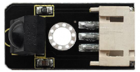
As for an infrared receiver module, it is mainly composed of an infrared receiving head. This device integrates with reception, amplification and demodulation. Its internal IC has been demodulated, outputting Digital signal. Suitable for IR remote control and infrared data transmission.
The infrared receiver module has only three pins (Signal, VCC, GND), very convenient to communicate with Arduino and other microcontrollers.
Parameters of IR Receiver:
- 1)Operating Voltage: 3.3-5V(DC)
- 2)Interface: 3PIN
- 3)Output Signal: Digital signal
- 4)Receiving Angle: 90 degrees
- 5)Frequency: 38khz
- 6)Receiving Distance: 18m
Wiring Diagram:
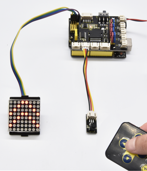
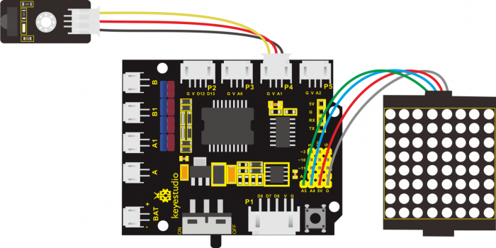
Note: stack the motor drive shield on the REV4 board; connect the infrared receiver sensor to P4(G、V、A1) connector on the motor drive shield. If the digital ports are not enough, analog port can be used as digital port. Analog port A0 corresponds to digital port14; A1 corresponds to digital port15.
Connect dot matrix module to motor drive shield (pin G for GND, V for 5V, SDA for A4, SCL for A5). Connect the power to BAT connector.
Coding:
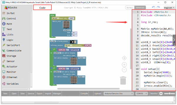
Now write the program. When aligning at the IR receiver, press the key on the IR remote control, available to check the input signal change of IR receiver on the serial monitor.
Go to “Control”, drag out the block; and drag the
![]() block from “SerialPort” into the “setup” block.
block from “SerialPort” into the “setup” block.
Next, IR receiver will receive the infrared signal when press different keys on the IR remote control.
We first click the imported library“Small_Turtle_Robot”, drag out the block ; drag the block
![]() from “SerialPort” into the infrared receiver block just made.
from “SerialPort” into the infrared receiver block just made.
Then go to “Variables”, drag out the block ![]() into the block
into the block![]() .
.
So the infrared receiver can receive the infrared signal.
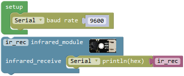
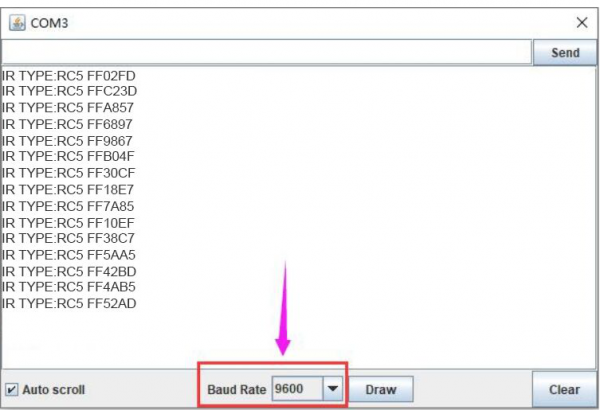
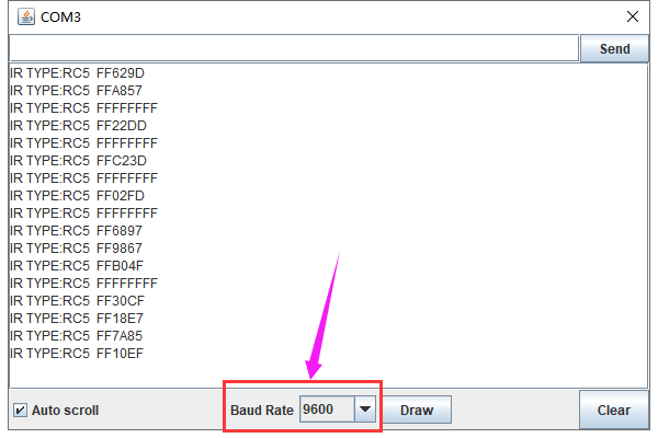
Upload this code, open the serial monitor; aimed at the infrared receiver sensor, press the key on the IR remote control, IR receiver will receive the infrared signal, and indicator turns on red. And you can see the key encoding on the serial monitor.
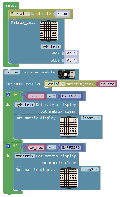
Next move on to realize the IR receiver controlling dot matrix displaying pattern with IR remote control.
Press the front key ![]() on the IR remote control, dot matrix displays a front pattern; press the key
on the IR remote control, dot matrix displays a front pattern; press the key ![]() , dot matrix displays STOP pattern. So here we call the if statement
, dot matrix displays STOP pattern. So here we call the if statement  from the “Control”. According to the measured result, we know the infrared encoding(string value) of front key
 ![]() is FF629D; the infrared encoding(string value) of key
is FF629D; the infrared encoding(string value) of key ![]() is FF02FD.
is FF02FD.
As the command key of IR remote control is hexadecimal code, the front must add 0x.
If ir_rec=0xFF629D, press the front key ![]() on the IR remote control,dot matrix displays a front pattern.
on the IR remote control,dot matrix displays a front pattern.
Go to the “Logic”, drag out the block ![]() into the if statement, and drag out the block
into the if statement, and drag out the block ![]() from the “Variables” into the first input box at the left side of “=”; drag the
from the “Variables” into the first input box at the left side of “=”; drag the ![]() from the “Math” into the second input box at the right side of “=” and type “0xFF629D” , like this:
from the “Math” into the second input box at the right side of “=” and type “0xFF629D” , like this: .
.
First set up the dot matrix display, click “Small_Turtle_Robot”, drag out the block into the setup block; here default SDA pin to A4, SCL pin to A5.
And again drag out the block
into the setup block; here default SDA pin to A4, SCL pin to A5.
And again drag out the block![]() and
and  into the do statement, click the drop-down triangle to select front2.
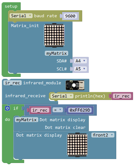
Next duplicate the block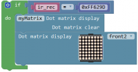 once and change “0xFF629D” to “0xFF02FD” and click the drop-down triangle to select stop2.
What you will see:
Upload the code success, open the monitor and set the baud rate to 9600. Turn the Slide switch ON.
Aimed at the infrared receiver, press your remote control to send the signal, and you will see the encoding of each button on the remote control.
Note if press the control button too long, easily appear unreadable code. Shown as below figure.
If receive the ![]() up button value from IR remote control, LED dot matrix shows the front icon
up button value from IR remote control, LED dot matrix shows the front icon![]() ; if receive the
; if receive the ![]() OK key value, shows“STOP”.
OK key value, shows“STOP”.
Below we have listed out each button value of keyestudio remote control. So you can keep it for reference.
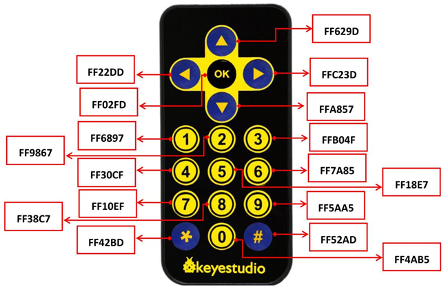
Little Knowledge:
1.In the code, we direct use the library ; the signal pin of IR receiver module is A1; the IR receiver receives an infrared signal and outputs 16-bit encoding, printing out on serial monitor (baud rate 9600).
2.We have tested out the 16-bit encoding of each button on the infrared remote control by source code.
Or you can see the button encoding chart shown above.
In the code, we can change the different key encoding to control dot matrix display different icons.
Extension Practice:
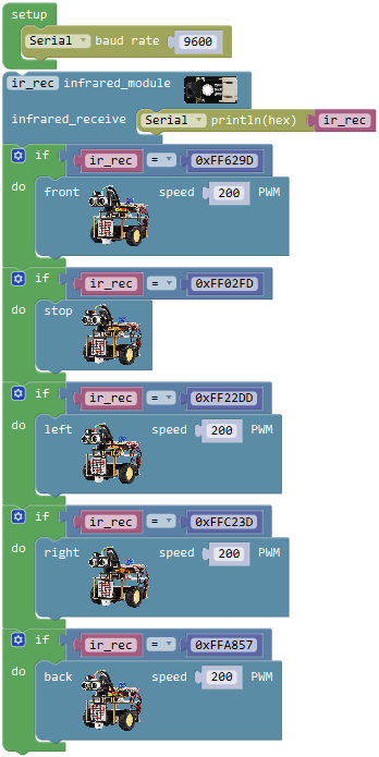
1.Driving the 2 motors’ turning direction and speed by infrared remote control.
(refer to project 9/10 - motor driving)
Combine infrared receiver and motors driving knowledge to build an infrared remote control car.
Project 7: Bluetooth Module
Description:
Bluetooth technology is a wireless standard technology that enables short-distance data exchange between fixed devices, mobile devices, and building personal area networks (using UHF radio waves in the ISM band of 2.4 to 2.485 GHz).
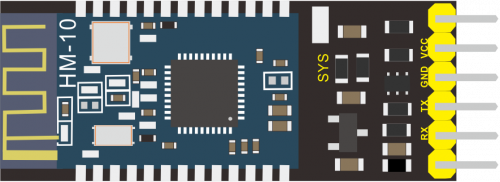
The Keyestudio HM-10 Bluetooth-4.0 V3 Module is a master-slave machine. When use as the Host, it can send commands to the slave actively; when use as the Slave, it can only receive commands from the host.
The HM-10 Bluetooth module supports the Bluetooth 4.0 protocol, which not only supports Android mobile, but also supports iOS system.
Technical Details:
- 1)Bluetooth protocol: Bluetooth Specification V4.0 BLE
- 2)No byte limit in serial port Transceiving
- 3)In open environment, realize 100m ultra-distance communication with iphone4s
- 4)USB protocol: USB V2.0
- 5)Working frequency: 2.4GHz ISM band
- 6)Modulation method: GFSK(Gaussian Frequency Shift Keying)
- 7)Transmission power: -23dbm, -6dbm, 0dbm, 6dbm, can be modified by AT command.
- 8)Sensitivity: ≤-84dBm at 0.1% BER
- 9)Transmission rate: Asynchronous: 6K bytes ; Synchronous: 6k Bytes
- 10)Security feature: Authentication and encryption
- 11)Supporting service: Central & Peripheral UUID FFE0, FFE1
- 12)Power consumption: Auto sleep mode, stand by current 400uA~800uA, 8.5mA during transmission.
- 13)Power supply: 5V DC
- 14)Working temperature: –5 to +65 Centigrade
Wiring Diagram:
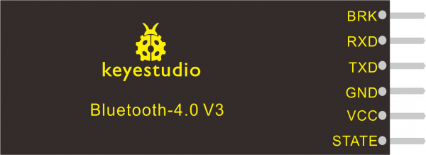
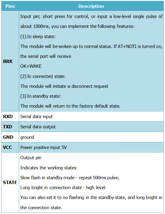
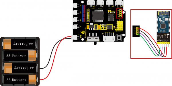
connect the VCC to 5V,GND to GND, TXD to RXD, RXD to TXD.
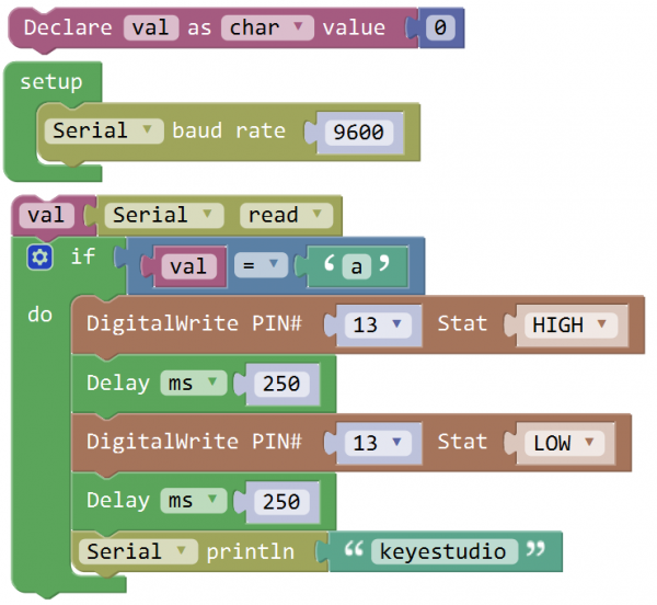
Test Code:
When uploading the code, CANNOT connect the Bluetooth module; otherwise uploading fails!
You are supposed to upload the code to control board, then connect the Bluetooth module.
Result:
First should install the APP on the cellphone. Download the APP from the link:
https://wiki.keyestudio.com/KS0455_keyestudio_HM-10_Bluetooth-4.0_V3_Compatible_with_HC-06_Pins
- For Android APP:
APP installed well, you can see the icon ![]() on your Android phone.
on your Android phone.
After wiring, upload the test code to REV4 board and then connect the Bluetooth module. Powered on, Bluetooth module’s built in LED flashes.
Open the Android APP![]() , click to scan device. As shown below.
, click to scan device. As shown below.
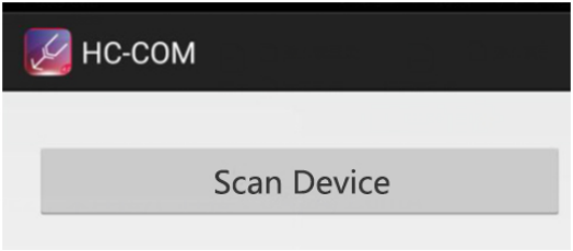
Click Scan Device to search the Bluetooth.
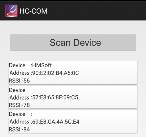
Click the first device  to connect the Bluetooth.
Connected, built-in LED on the Bluetooth module is normally on. APP interface will show the state connected.
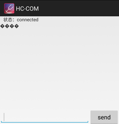
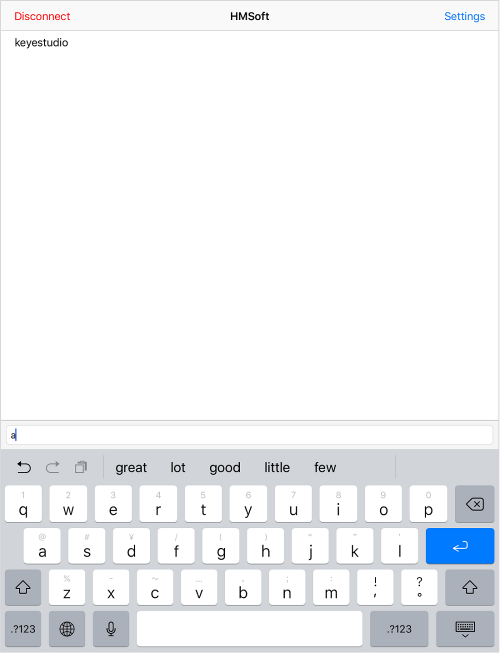
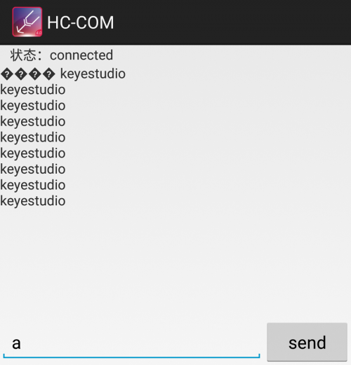
On the bar enter letter a, and click to send, APP will print out the character “keyestudio” and D13 indicator on the REV4 board will flash once.
Continue to send the letter a, APP prints out multiple “keyestudio” character and D13 indicator flashes.
- For mac/iOS APP
You need to download the mac/iOS compatible APP in APP store.
First we enter the APP store, search hm10, and select the hm10 bluetooth serial lite.
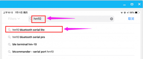
Click to install the APP, as shown below.
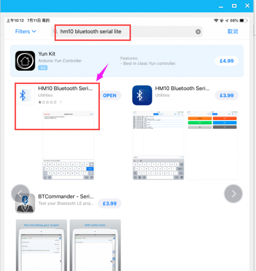
APP installed well, a Bluetooth icon![]() will pop up on your phone. Click to enter the APP.
will pop up on your phone. Click to enter the APP.
Upload the test code to control board successfully, then plug in the Bluetooth module.
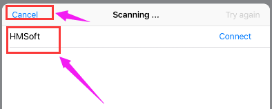
Open the Bluetooth APP, click ![]() to start searching and pairing the Bluetooth module. Click
to start searching and pairing the Bluetooth module. Click ![]() to start connecting HM-10 Bluetooth module.
to start connecting HM-10 Bluetooth module.
Connected, the built-in LED on the Bluetooth module will be from quick flash to normally on.
On the input bar enter a letter a, and click to send, APP will print out the character “keyestudio” and D13 indicator on the REV4 board will flash once.
Continue to send the letter a, APP prints out multiple “keyestudio” characters and D13 indicator flashes.
