KS0446 Keyestudio Frog Robot for Arduino Graphical Programming: Difference between revisions
Keyestudio (talk | contribs) |
Keyestudio (talk | contribs) |
||
| Line 235: | Line 235: | ||
<br> | <br> | ||
'''Introduction:'''<br> | '''Introduction:'''<br> | ||
Servo motor is a position control rotary actuator. It mainly consists of housing, circuit board, core-less motor, gear and position sensor. | Servo motor is a position control rotary actuator. It mainly consists of housing, circuit board, core-less motor, gear and position sensor. <br> | ||
Included with your servo motor you will find a variety of black mounts that connect to the shaft of your servo. | Included with your servo motor you will find a variety of black mounts that connect to the shaft of your servo. <br> | ||
You may choose to attach any mount you wish for the circuit. It will serve as a visual aid, making it easier to see the servo spin. | You may choose to attach any mount you wish for the circuit. It will serve as a visual aid, making it easier to see the servo spin.<br> | ||
Working principle: | '''Working principle:'''<br> | ||
The receiver or MCU outputs a signal to the servomotor. The motor has a built-in reference circuit that gives out reference signal, cycle of 20ms and width of 1.5ms. The motor compares the acquired DC bias voltage to the voltage of the potentiometer and outputs a voltage difference. | The receiver or MCU outputs a signal to the servomotor. The motor has a built-in reference circuit that gives out reference signal, cycle of 20ms and width of 1.5ms. The motor compares the acquired DC bias voltage to the voltage of the potentiometer and outputs a voltage difference. <br> | ||
Servo motor comes with many specifications. But all of them have three connection wires, distinguished by brown, red, orange colors (different brand may have different color). | Servo motor comes with many specifications. But all of them have three connection wires, distinguished by brown, red, orange colors (different brand may have different color). <br> | ||
Brown one is for GND, red one for power positive, orange one for signal line. | <span style="color:red"> Brown one is for GND, red one for power positive, orange one for signal line. </span><br> | ||
The rotation angle of servo motor is controlled by regulating the duty cycle of PWM (Pulse-Width Modulation) signal. The standard cycle of PWM signal is 20ms (50Hz). | The rotation angle of servo motor is controlled by regulating the duty cycle of PWM (Pulse-Width Modulation) signal. The standard cycle of PWM signal is 20ms (50Hz). <br> | ||
Theoretically, the width is distributed between 1ms-2ms, but in fact, it's between 0.5ms-2.5ms. The width corresponds the rotation angle from 0° to 180°. | Theoretically, the width is distributed between 1ms-2ms, but in fact, it's between 0.5ms-2.5ms. The width corresponds the rotation angle from 0° to 180°. <br> | ||
But note that for different brand motor, the same signal may have different rotation angle. | But note that for different brand motor, the same signal may have different rotation angle. <br> | ||
'''Connection Diagram:'''<br> | |||
Connection Diagram | Simply stack the keyestudio Nano ch340 into the keystudio NANO shield. <br> | ||
Simply stack the keyestudio Nano ch340 into the keystudio NANO shield. | Connect the Servo pin to digital pin 4 <br> | ||
Connect the Servo pin to digital pin 4 | |||
Source Code | '''Source Code:'''<br> | ||
We can set the HIGH/LOW for corresponding pins in the Mixly blocks software, so as to adjust the servo angle; furthermore, we specially create the robot library, so easy to control the servo angle with simplified code. | We can set the HIGH/LOW for corresponding pins in the Mixly blocks software, so as to adjust the servo angle; furthermore, we specially create the robot library, so easy to control the servo angle with simplified code. <br> | ||
'''Test Result:'''<br> | |||
Upload the Code success, press down the Power_Switch, the servo motor will rotate back and forth from 0°to 180°.<br> | |||
Little Knowledge: | '''Little Knowledge:''' <br> | ||
① this piece of block is used to direct regulate the servo. connect the servo signal pin to D4; set the servo angle to a variable, that is, | ① this piece of block is used to direct regulate the servo. connect the servo signal pin to D4; set the servo angle to a variable, that is, | ||
This defined variable is applied to regulate the servo angle. | This defined variable is applied to regulate the servo angle. <br> | ||
Because the servo angle is in the range of 0-180°, the range of variable should set from 0 to 180. | Because the servo angle is in the range of 0-180°, the range of variable should set from 0 to 180. <br> | ||
The delay period is in milliseconds, so if you want the LED display as fast, change the value 10. | The delay period is in milliseconds, so if you want the LED display as fast, change the value 10. <br> | ||
This block means variable i increases from 0 to 180, and each step increases 1. | This block means variable i increases from 0 to 180, and each step increases 1.<br> | ||
This block means variable i reduces from 180 to 0, and each step reduces 1. | This block means variable i reduces from 180 to 0, and each step reduces 1.<br> | ||
Extension Practice: | '''Extension Practice:''' <br> | ||
① Refer to the test code. Try to reset the servo pin and rotation speed | ① Refer to the test code. Try to reset the servo pin and rotation speed <br> | ||
(Tips: set the delay time for servo angle ; or adjust to increase/reduce the step, which should be divisible by 180, like 2, 3, 5.) | ('''Tips:''' set the delay time for servo angle ; or adjust to increase/reduce the step, which should be divisible by 180, like 2, 3, 5.) | ||
Revision as of 16:44, 7 August 2019
About the tutorial
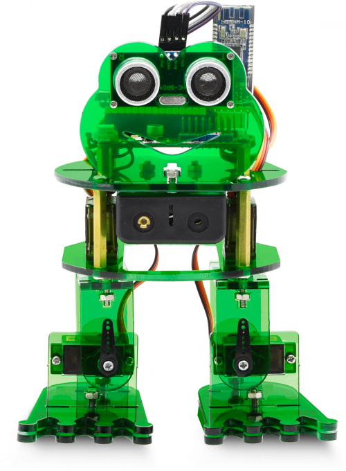
What an amazing Otto Frog Robot is coming!
This kit provides a perfect opportunity to build your very first robot, and it makes the process of learning about robotics easy, interactive, and FUN!
The kit is based on the keyestudio nano ch340, compatible with both Arduino open-source platform and Mixly Blocks coding.
You can program your own robot to walk, dance and follow obstacle, easy to build and code. No prior tech experience required!
Through play and experimentation children can exercise computational thinking and put skills into practice that are necessary for problem solving.
Features
- Voltage input: DC 7-12V
- Ultrasonic module for measuring the front obstacle distance, forming obstacle avoiding system;
- Pairing HM-10 Bluetooth module with mobile Bluetooth to navigate the frog robot;
- Providing the mobile APP compatible with both Android and mac system;
- The NANO shield extends 12 digital pins and 8 analog pins into 3pin header, easy to connect a couple of sensor modules for projects extension;
- The NANO shield comes with an I2C communication pin, able to connect I2C communication module for experiment extension.
Parts List
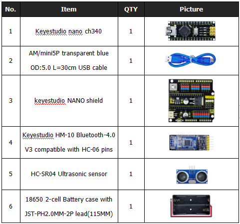
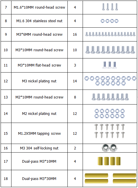
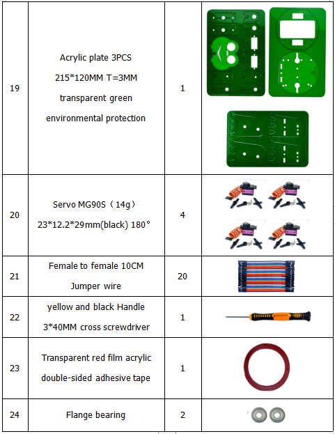
In this keyestudio frog robot kit package, you’ll receive all the components needed to build your own robot, easy to code and learn to play.
Get Started with Mixly and ARDUINO
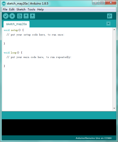
1)Installing Arduino IDE
When program the UNO development board, you can download the Arduino integrated development environment from the link:
See more contents at:
- https://wiki.keyestudio.com/Getting_Started_with_Arduino
- https://wiki.keyestudio.com/How_to_Download_Arduino_IDE
- https://wiki.keyestudio.com/How_to_Install_Arduino_Driver
- https://wiki.keyestudio.com/How_to_Install_Arduino_Library
The functions of each button on the Toolbar are listed below:
![]()
Or you can browse the KEYESTUDIO website at this link, https://www.keyestudio.com/

2)Introduction for Mixly Blocks
Mixly is a free open-source graphical Arduino programming software, based on Google’s Blockly graphical programming framework, and developed by Mixly Team@ BNU.
It is a free open-source graphical programming tool for creative electronic development; a complete support ecosystem for creative e-education; a stage for maker educators to realize their dreams.
More info please check the link to download the Mixly blocks software.
- https://wiki.keyestudio.com/Getting_Started_with_Mixly
- https://wiki.keyestudio.com/Download_Mixly_Software
- https://wiki.keyestudio.com/How_to_Import_Mixly_Library
Before starting the robot projects, please click the link to get the basic understanding of Mixly software.
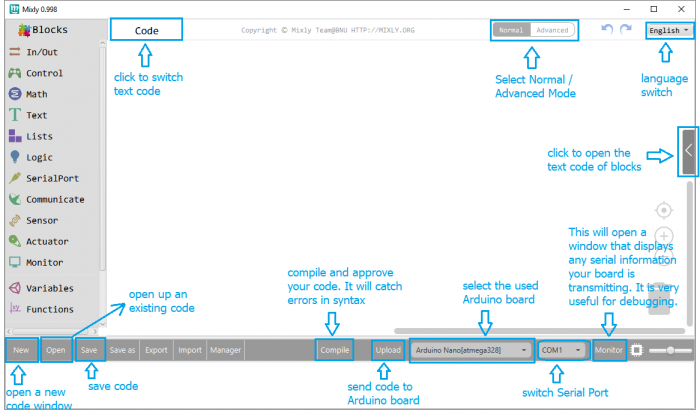
3)Import Robot Library
For the robot kit, we have developed keyestudio frog robot library.
Don’t forget to import the keyestudio OTTO_Frog robot library to Mixly software before coding the robot projects.
Must import the robot library first, or else you can’t check all the test code.
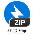
Unzip the OTTO_Frog library package, you can see the OTTO_Frog_Robot XML.document.

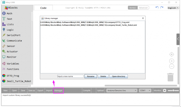
Then import this document into Mixly library. Import custom library successfully!
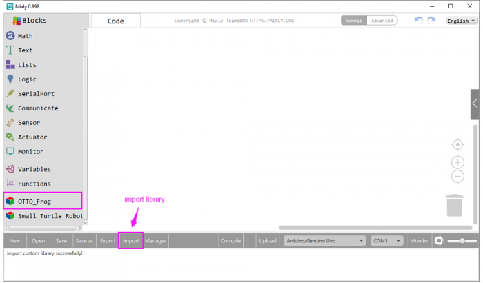
You are able to click “Manager” to manage all imported libraries.
Note: sometimes it may exists a conflict between libraries, so should keep only correct car library when using and delete other library.
Hardware Projects
As you work your way through each project, you will learn to how to program the robot to move, dance, and follow obstacles.
Project 1: Keyestudio NANO CH340
Introduction:
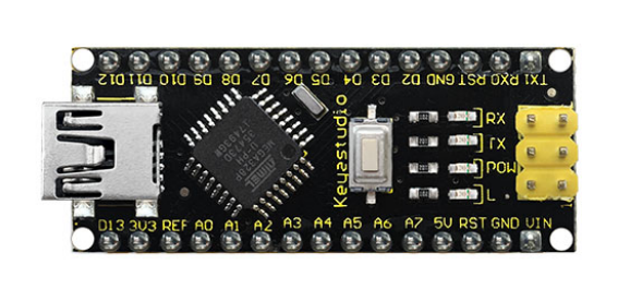
keyestudio Nano CH340 is a small, complete, and breadboard-friendly board based on the ATmega328P-AU. Compared with ARDUINO NANO, the USB-to-serial port chip used in keyestudio Nano is CH340G, so that the using method is the same except the driver installation file.
It has 14 digital input/output pins (of which 6 can be used as PWM outputs), 8 analog inputs, a 16 MHz crystal oscillator, a mini USB port, an ICSP header and a reset button.
Note that ICSP (In-Circuit Serial Programming) header is used to program the firmware to ATMEGA328P-AU, but generally the chip has been preburned before leave the factory. So use it less.
The keyestudio Nano can be powered via the Mini-B USB connection, or female headers Vin/GND (DC 7-12V).
TECH SPECS:
| Microcontroller | ATmega328P-AU |
|---|---|
| Operating Voltage | 5V |
| Input Voltage (recommended) | DC7-12V |
| Digital I/O Pins | 14 (D0-D13) (of which 6 provide PWM output) |
| PWM Digital I/O Pins | 6 (D3, D5, D6, D9, D10, D11) |
| Analog Input Pins | 8 (A0-A7) |
| DC Current per I/O Pin | 40 mA |
| Flash Memory | 32 KB of which 2 KB used by bootloader |
| SRAM | 2 KB |
| EEPROM | 1 KB |
| Clock Speed | 16 MHz |
| LED_BUILTIN | D13 |
Element and Interfaces:
Here is an explanation of what every element and interface of the board does:
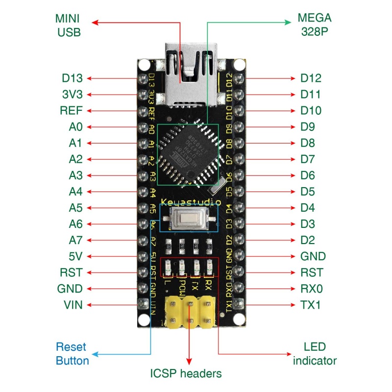
Specialized Functions of Some Pins:
- Serial communication: 0 (RX) and 1 (TX). Used to receive (RX) and transmit (TX) TTL serial data.
- PWM (Pulse-Width Modulation): D3, D5, D6, D9, D10, D11
- External Interrupts: D2 (interrupt 0) and D3 (interrupt 1). These pins can be configured to trigger an interrupt on a low value, a rising or falling edge, or a change in value. See the attachInterrupt() function for details.
- SPI communication: D10 (SS), D11 (MOSI), D12 (MISO), D13 (SCK).
- IIC communication: A4 (SDA); A5(SCL)
Project 2: keyestudio NANO Shield
Introduction:
keyestudio Nano ch340 is a tiny control board based on Arduino platform, which is deeply popular.
However, if want to connect several sensor modules to keyestudio Nano ch340, and connect external power, we need to use breadboard and a bunch of jumper wires, which is pretty inconvenient.
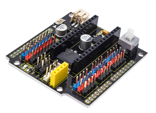
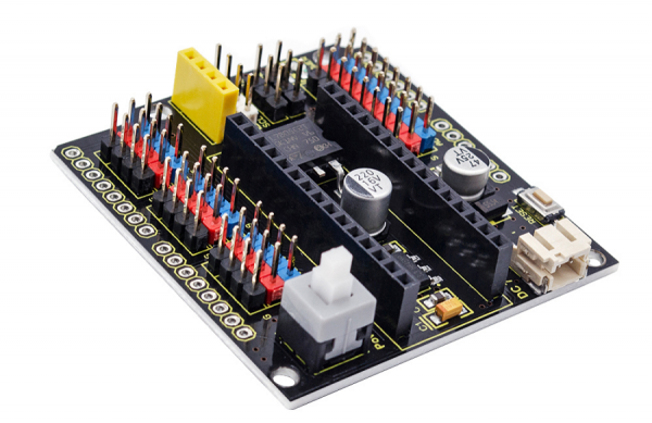
We specially design this NANO shield, fully compatible with keyestudio Nano ch340.
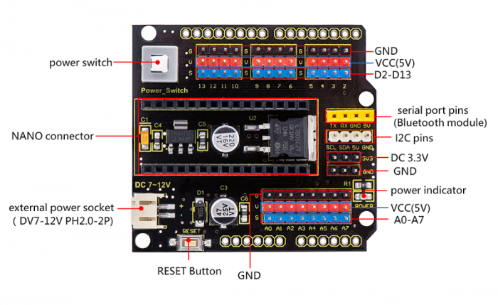
TheNANO shield has brought out digital and analog pins of keyestudio Nano ch340 into 3PIN headers (GND, 5V, Signal) with pin pitch of 2.54mm.
The NANO shield also leads out frequently-used communication pins, such as serial port communication and I2C communication. It’s greatly easy to connect keyestudio Nano ch340 and other sensor modules.
It comes with a power indicator and a reset button as well.
For external power, the NANO shield comes with a PH2.0-2P connector (input DC7-12V); a Power_Switch for power control.
To supply power for other sensors, the NANO shield comes with a 3-way DC3.3V power output pin header with pin pitch of 2.54mm.
It comes with 4 fixing holes with a diameter of 3mm, so easy to mount on other devices.
Features:
- 1.Extends 12 digital pins into 3pin header
- 2.Extends 8 analog pins into 3pin header
- 3.Comes with a serial communication pin header (for Bluetooth module)
- 4.Comes with an I2C communication pin
- 5.Comes with 3-way DC 3.3V power output pin
- 6.Comes with a power indicator and a reset button
- 7.Comes with an external power connector(PH2.0-2P)and a control button
- Voltage input: DC7-12V
- Power connector: PH2.0-2P
- Pin/Female header: 2.54mm
- Fixing hole diameter: 3mm
Controller Compatible:
Use Method:
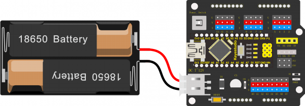
Simply stack the keyestudio Nano ch340 into the keystudio NANO shield. Supply the power with batteries via white connector.
Project 3: Adjusting Servo Angle
[[image:|thumb|500px|right|Keyestudio NANO Shield (Black and Eco-friendly) ]]
Introduction:
Servo motor is a position control rotary actuator. It mainly consists of housing, circuit board, core-less motor, gear and position sensor.
Included with your servo motor you will find a variety of black mounts that connect to the shaft of your servo.
You may choose to attach any mount you wish for the circuit. It will serve as a visual aid, making it easier to see the servo spin.
Working principle:
The receiver or MCU outputs a signal to the servomotor. The motor has a built-in reference circuit that gives out reference signal, cycle of 20ms and width of 1.5ms. The motor compares the acquired DC bias voltage to the voltage of the potentiometer and outputs a voltage difference.
Servo motor comes with many specifications. But all of them have three connection wires, distinguished by brown, red, orange colors (different brand may have different color).
Brown one is for GND, red one for power positive, orange one for signal line.
The rotation angle of servo motor is controlled by regulating the duty cycle of PWM (Pulse-Width Modulation) signal. The standard cycle of PWM signal is 20ms (50Hz).
Theoretically, the width is distributed between 1ms-2ms, but in fact, it's between 0.5ms-2.5ms. The width corresponds the rotation angle from 0° to 180°.
But note that for different brand motor, the same signal may have different rotation angle.
Connection Diagram:
Simply stack the keyestudio Nano ch340 into the keystudio NANO shield.
Connect the Servo pin to digital pin 4
Source Code:
We can set the HIGH/LOW for corresponding pins in the Mixly blocks software, so as to adjust the servo angle; furthermore, we specially create the robot library, so easy to control the servo angle with simplified code.
Test Result:
Upload the Code success, press down the Power_Switch, the servo motor will rotate back and forth from 0°to 180°.
Little Knowledge:
① this piece of block is used to direct regulate the servo. connect the servo signal pin to D4; set the servo angle to a variable, that is,
This defined variable is applied to regulate the servo angle.
Because the servo angle is in the range of 0-180°, the range of variable should set from 0 to 180.
The delay period is in milliseconds, so if you want the LED display as fast, change the value 10.
This block means variable i increases from 0 to 180, and each step increases 1.
This block means variable i reduces from 180 to 0, and each step reduces 1.
Extension Practice:
① Refer to the test code. Try to reset the servo pin and rotation speed
(Tips: set the delay time for servo angle ; or adjust to increase/reduce the step, which should be divisible by 180, like 2, 3, 5.)
